Abstract
In the present work, heat transfer coefficients (h) along different cooling zones of a continuous caster billet machine were determined during casting of low and medium carbon steels. The effects of casting parameters, such as machine characteristics, the ingot dimension, mold, sprays zones, radiant cooling, melt composition, and casting temperature were investigated and correlated with heat transfer coefficients. By using industrial measured billet surface temperatures, linked with a numerical solution of the solidification problem, ingot/cooling zones heat transfer coefficients were quantified based on the solution of the inverse heat conduction problem (IHCP). The experimental temperatures were compared with simulations furnished by an explicit finite difference numerical model, and an automatic search has selected the best theoretical–experimental fit from a range of values of h. The computer software algorithm has been developed to simulate temperature profiles, solid shell growth, phase transformations, and the point of complete solidification in continuous casting of steel billets and blooms. Industrial experiments were monitored with an optical infrared pyrometer to analyze the evolution of surface temperatures during solidification along the machine. The results permitted the establishment of expressions of h as a function of position along the caster, for different steel compositions, casting parameters and melt superheats.
Nomenclature
| A = | = | area (m2) |
| c = | = | specific heat (Jkg−1 K−1) |
| CT = | = | thermal capacitance (J K−1) |
| fs = | = | solid fraction |
| h = | = | metal/mold heat transfer coefficient (W m−2 K−1) |
| hm = | = | metal/mold heat transfer coefficient (W m−2 K−1) |
| hS = | = | metal/sprays heat transfer coefficient (W m−2 K−1) |
| hR = | = | metal/environment heat transfer coefficient (W m−2 K−1) |
| i, j = | = | positions of element |
| k = | = | thermal conductivity (W m−1 K−1) |
| L = | = | latent heat of fusion (J kg−1) |
| n, n + 1 = | = | refer to temperatures before and after the incremental time interval |
| = | internal heat source (W) | |
| RT = | = | thermal resistance at the heat flux line (K W−1) |
| t = | = | time (s) |
| T = | = | temperature (°C) |
| Test = | = | estimated temperature (°C) |
| Texp = | = | experimental temperature (°C) |
| Tpouring = | = | pouring temperature (°C) |
| TL = | = | liquidus temperature (°C) |
| TP = | = | pouring temperature (°C) |
| To = | = | water-cooling temperature (°C) |
| Vcasting = | = | casting velocity (m s−1) |
| x, y = | = | space coordinates (m) |
| Z = | = | position along the caster (m) |
| Δh = | = | heat transfer step (W m−2 K−1) |
| ΔT = | = | gradient temperature (°C) |
| Δt = | = | time interval (s) |
| ∂T/∂t = | = | cooling rate (K s−1) |
| φ = | = | sensitivity coefficient |
| ρ = | = | density (kg m−3) |
| α = | = | thermal diffusivity (m2 s−1) |
1. Introduction
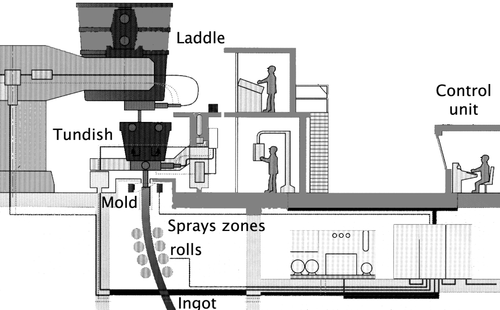
The continuous casting process is responsible to most of the steel production in the world, and has largely replaced conventional ingot casting/rolling for the production of semi-finished steel-shaped products. The process is essentially a process of heat transfer between the metal and different cooling zones. shows a schematic representation of a continuous caster and the different cooling zones along the machine. The casters have been implemented with modern equipments for billets, slabs or blooms, multiple casting and process control.
Figure 1. Schematic representation of the continuous casting process.
For the purpose of accurate mathematical modeling of solidification in the continuous casting of steel, it is essential that correct boundary conditions be established along the caster machine during casting operations. Heat transfer at the metal/cooling interface is one of these boundary conditions, which is of central importance when considering the magnitude of heat transfer during the stages of solidification in the mold, spray zones, or natural cooling.
The present study describes a method for obtaining transient interfacial heat transfer coefficients as a function of position along the caster, from temperature experimental data concerning the solidification of steel during continuous casting. Ingot surface experimental temperatures obtained by optical pyrometers are compared with simulations furnished by a numerical model, and an automatic search selects the best fit from a range of values of interfacial heat transfer coefficients by inverse heat conduction problem (IHCP) procedure. The effects of alloy composition, casting, and dimensions of the ingot are also investigated.
2. Heat transfer coefficient
Several studies have attempted to quantify the metal/cooling transient interfacial heat transfer during solidification in continuous casting processes during operation in terms of a heat transfer coefficient Citation1–5. These studies have highlighted the different factors affecting heat flow across metal/cooling interface during solidification. These factors include the thermophysical properties of the contacting materials, the casting and mold geometry, melt superheat, and mainly the specific configurations of each machine, as well as the operational casting parameters and solidification conditions. The heat transfer coefficients vary for each region along the machine Citation6–12. Most of the methods of calculation of h in the existing literature are based on temperature histories at points of the casting or mold together with mathematical models of heat transfer during solidification. Among these methods, those based on the solution of the inverse conduction problem have been widely used in the quantification of the transient interfacial heat transfer Citation13–20.
This method makes a complete mathematical description of the physics of the process and is supported by temperatures measurements at known locations inside the heat conducting body. The temperature files containing the experimentally monitored temperatures are used in a finite difference heat flow model to determine h, as described in a previous article Citation17.
2.1. Inverse procedure
The process at each time step included the following: a suitable initial value of h is assumed, and with this value the temperature of each reference location in casting at the end of each time interval Δt is simulated by using an explicit finite difference technique. The correction in h at each interaction step is made by a value Δh, and new temperatures are estimated [Test(h + Δh)] or [Test(h − Δh)]. With these values, sensitivity coefficients (φ) are calculated for each interaction, given by
(1)
In the present work, a similar procedure determines the values of h, which minimizes an objective function defined by:
(2)
where Test and Texp are, respectively, the estimated and experimentally measured temperatures at various positions and times along the machine during casting operation, and n is the iteration stage. The solution sequence involves the calculation of the sensitivity coefficients for estimated measured temperatures in order to analyze the infuence of h in the temperature field. The assumed value of h is corrected using the relation:
(3)
The above indicated procedure is repeated for a new value of h, and is continued until
(4)
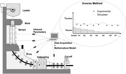
The inverse problem consists of estimating the boundary heat transfer coefficients at the metal/cooling interfaces along different cooling zones of a continuous caster billet machine. Experimental surface temperatures measured by infrared pyrometers were compared to estimated temperatures computed from the solution of a mathematical solidification heat transfer model. The match can be done by minimizing the standard least squares norm with respect to each of the unknown heat transfer coefficient components. The procedure has been also detailed by the present authors in a previous publication Citation18.
A one-dimensional solidification heat transfer model of the metal/mold system that predicts the thermal field was used to provide a forward problem solution for the inverse problem. The method consists of estimating the boundary heat transfer coefficient at the metal/cooling interfaces from ingot surface measured temperatures along the machine (sprays zones and radiation zones). The inverse problem can be stated as follows: given M measured temperatures Texp (j = 1, 2, 3, … , N), estimating the heat transfer coefficient given by its components hi (i = 1, 2, 3, … , N). shows a schematic of the stated problem.
Figure 2. Diagram showing domain for IHCP.
The representation of the heat transfer coefficients along the different cooling zones in the continuous casting machine was based on the following key assumptions:
Mold: h1(x) is considered variable and represented as a function of position along the length mold Citation12; Sprays zone and radiation zones: h2 to hn(x) is considered constant along each cooling zone and calculated by the IHCP method.
To solve the problem, the estimated surface temperatures Tiest (i = 1, 2, 3, … , N) computed from the solution of the direct problem using the estimated values of the heat transfer coefficient components hi (i = 1, 2, 3, … , N), should match the media ingot surface measured temperatures Tiexp (i = 1, 2, 3, … , N) obtained by the infrared pyrometers located at specific locations, as close as possible to the billet surface. This matching can be done by minimizing the standard least squares norm with respect to each of the unknown heat transfer coefficient components.
3. Mathematical solidification heat transfer model
The mathematical formulation of heat transfer to predict the temperature distribution during solidification is based on the general equation of heat conduction in unsteady state, which is given for two-dimensional heat flux by equation (Equation5(5) ):
(5)
where ρ is density (kg m−3); c is specific heat (Jkg−1 K−1); k is thermal conductivity (Wm−1 K−1); ∂T/∂t is cooling rate (K s−1), T is temperature (K), t is time (s), x and y are space coordinates (m), and
represents the term associated to the internal heat generation due to the phase change. It was assumed that the thermal conductivity, density, and specific heat vary only with temperature.
Approximating equation (Equation5(5) ) by finite difference terms, we obtain equation (Equation6
(6) ):
(6)
where i, j are the positions of element, n and n + 1 refer to temperatures before and after the incremental time interval, respectively, and the stability criteria is given by
where α = k/ρ c is the thermal diffusivity (m2 s−1).
3.1. Phase change
In this study, a fixed grid methodology was used with a heat source term due to the phase transformation, which is given by an explicit solid fraction–temperature relationship. The solid fraction depends on a number of parameters, however, and it is quite reasonable to assume fs varying only with temperature, where fs is the solid fraction and L is the latent heat of fusion (J kg−1). So, we can write c′ = c − L(∂fs/∂T) and the term L(∂fs/∂T) is called pseudo-specific heat. At the range of temperatures where solidification occurs for metallic alloys, the physical properties will be evaluated taking into account the amount of liquid and solid that coexists in equilibrium at each temperature. The sub-indices S and L, respectively, indicate solid and liquid states. For carbon steels, fs is appropriately described by the lever rule.
3.2. Analogy between thermal systems and electrical circuits
Multiplying equation (Equation6(6) ) by Δx Δy Δz, where At = Δy Δz, we obtain:
(7)
where At is the area of element i, j (m2). By using an analogy between a thermal system and the passive elements of an electrical circuit, the thermal capacitance (CT) represents the energy accumulated in a volume element i, j from the grid, and is given by Citation21:
(8)
where Δx Δy Δz is the volume of the element i, j.
The thermal flux between central points has a thermal resistance at the heat flux line (RT) from point i + 1, j or i − 1, j to point i, j or i, j + 1 or i, j − 1 to i, j given by:
(9)
where Δx and Δy correspond to the distance between central points of elements.
Then, equation (Equation7(7) ) becomes:
(10)
or
(11)
where
(12)
(13)
(14)
(15)
(16)
Equation (Equation11(11) ) is generic and can be applied to any geometry, by varying only area and volume to be considered. The stability criterion is
.
3.3. Boundary conditions
The application of the solidification model to the continuous casting of billets was based on the following key assumptions Citation22,Citation23:
| a. | Two-dimensional heat transfer was considered: z-direction ⇒ ∂T/∂z = 0; | ||||
| b. | A control volume element was placed in a transverse section and was analyzed from the meniscus up to the cut-off region: Z = Vcasting Δt, where Z (m) is position along the caster and Vcasting (m s−1) is casting velocity; | ||||
| c. | The billet symmetry permits that only one-quarter of the cross section be modeled for a full thermal evolution characterization; | ||||
| d. | The meniscus surface was assumed to be flat; | ||||
| e. | The mold is considered uniform and with an initial temperature equal to the water-cooling temperature (To); | ||||
| f. | The surface temperature of the molten metal is considered equal to the pouring temperature and given by Tpouring = Ttundish − 20°C; | ||||
| g. | At the range of temperatures where solidification occurs for metallic alloys, the physical properties will be evaluated taking into account the amount of liquid and solid that coexists in equilibrium at each temperature:
| ||||
| h. | The initial transient metal/mold heat transfer coefficients (hm) used in this work, are those proposed in the literature Citation12 and the metal/sprays and metal/environment heat transfer coefficients (hs and hR) are determined by the IHCP method by using experimental ingot surface temperatures obtained by optical pyrometers. | ||||
| i. | Effect of mold oscillation, mold curvature, segregation, and melt level fluctuation in the mold were considered in the knowledge base. | ||||
4. Experimental procedure
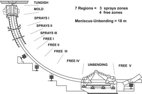
The experimental data were obtained in an industrial caster by using optical infrared mobile pyrometers located along the secondary cooling zones and radiation zones. The machine was divided in eleven different “regions”: mold, sprays zone I, sprays zone II, sprays zone III, free (metal/environment heat flow) I, free II, free III, free IV, unbending point, free V, free VI, and free VII. Surface temperatures were measured in the middle or end of each region called “positions”. A schematic representation of the caster machine and the locations where surface temperatures were monitored until position 4 are shown in .
Figure 3. Location of experimental measured surface temperatures along the continuous casting process.
The input parameters and thermophysical properties used in casting operations and simulations are presented in . The temperature files containing the experimentally monitored temperatures during the continuous casting process were used in a finite difference heat flow program in order to determine nominal metal/sprays heat transfer coefficients (h).
Table 1. Input parameters for SAE 1007 and SAE 1025 billet conditions 24,25
In this study the continuous casting of different dimensions and carbon contents were analyzed: SAE 1007 (150 × 150 mm) and SAE 1025 (240 × 240 mm).
5. Results and discussion
To determine the metal/sprays heat transfer coefficients for each spray cooling zone as a function of water flow rates, ingot surface measured temperatures shown in and were used. The positions appearing in these tables are the same presented in corresponding to different distances from the top of the mold.
Table 2. xperimental surface temperature measured during casting (1007 steel)
5.1. SAE 1007
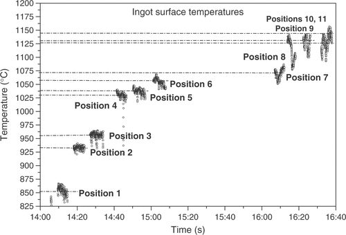
shows examples of experimental data measured by optical pyrometers in different positions along the machine during casting. The values used in the determination of the metal/cooling heat transfer coefficients are average values of the measured values taken during 5 min.
Figure 4. Example of experimental ingot surface temperatures obtained during continuous casting.
shows a comparison between experimental and simulated data for the 1007 steel billet. The simulation was based on metal/mold heat transfer coefficients proposed by Toledo Citation12 and the metal/sprays heat transfer coefficients were determined by the present approach. A good agreement can be observed with differences between experimental and simulated values being lower than 20°C. shows the experimental surface temperatures and those calculated by the mathematical solidification heat transfer model utilizing the heat transfer coefficients for each zone, respectively.
Figure 5. Comparison between calculated and experimental surface temperatures during casting of 1007 steel billets.
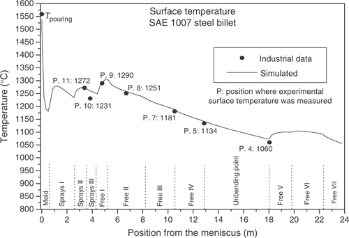
Table 3. Correlation between water flow rates and metal/sprays heat transfer coefficients and measured and calculated surface temperatures (1007 steel)
The main metallurgical parameters calculated by the mathematical model were (SAE 1007 billet): solid shell thickness at the mold exit: 13 mm; ingot surface temperature: 1181°C; ingot surface temperature at flame cut-off point: 1070°C; point of complete solidification: 17.13 m from the meniscus.
5.2. SAE1025
The main metallurgical parameters calculated by the mathematical model were (SAE 1025 billet): solid shell thickness at the mold exit: 25 mm; ingot surface temperature: 1038°C; ingot surface temperature at flame cut-off point: 845°C; point of complete solidification: 17.34 m from the meniscus. shows the experimental surface temperatures and shows the comparison between experimental and calculated values.
Figure 6. Comparison between calculated and experimental surface temperatures during casting of 1025 steel billets.
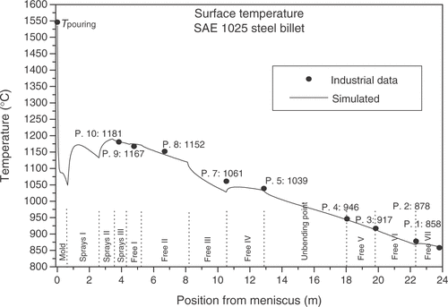
Table 4. Experimental surface temperature measured during casting (1025 steel)
The correlation between water flow rate and metal/sprays heat transfer coefficients, as well as calculated and measured temperatures during continuous casting of the 1025 steel billet can be seen in .
Table 5. Correlation between water flow rates and metal/sprays heat transfer coefficients and measured and calculated surface temperatures (1025 steel)
In both cases, a gradient method has been used to find the heat transfer coefficients corresponding to an increment of about 5 W m−2 K−1 and the criteria for convergence equal to a maximum difference between experimental and calculated ingot surface temperature values about 25°C. It can be observed in , that the ingot thermal profile for the SAE 1025 billet presents surface temperatures lower than those observed for the SAE 1007 billet.
6. Conclusions
From the experimental and theoretical results on continuous casting of different steel grades, the following conclusions can be drawn:
| • | For both the SAE 1007 and the SAE 1025 billets, a rapid drop in interfacial heat transfer coefficient occurs along the continuous casting machine; | ||||
| • | The metal/cooling (h) or the overall heat transfer coefficient (hg) can be expressed as a function of position, and depend on alloy composition, casting parameters and superheat. It is important to evidence that these results are valid only to specific casting conditions; | ||||
| • | The heat transfer coefficient in the sprays zones increases with decreasing casting dimensions; | ||||
| • | The use of an optical infrared mobile pyrometer has demonstrated to be efficient to measure ingot surface temperatures along the caster. This method can be applied to various casting operations permitting to develop correlations between metal/cooling heat transfer coefficients and operational parameters. | ||||
Acknowledgements
The authors acknowledge financial support provided by FAPESP (The Scientific Research Foundation of the State of São Paulo, Brazil), CNPq (The Brazilian Research Council) and State University of Campinas (UNICAMP). Marco Olívio Sotelo and Tiago Machado Ferraz are also acknowledged for helping with the computer programming.
Related Research Data
References
- Prates, M, and Biloni, H, 1972. Variables affecting the nature of chill-zone, Metallurgical Transactions 3A (1972), pp. 1501–1518.
- Ho, K, and Pehlke, RD, 1984. Mechanisms of heat transfer at a metal-mold interface, AFS Transactions 92 (1984), pp. 587–598.
- Ho, K, and Pehlke, RD, 1985. Metal-mold interfacial heat transfer, Metallurgical Transactions 16B (1985), pp. 585–594.
- Reddy, AV, and Beckermann, C, 1993. Measurements of metal-mold interfacial heat transfer coefficients during solidification of Sn and Sn–Pb alloys, Experimental Heat Transfer 6 (1993), pp. 111–129.
- Evans, JF, Kirkwood, DH, and Beech, J, 1991. The determination of metal-mold interfacial heat transfer coefficients and the prediction of gross shrinkage cavities in chill mold castings, The Minerals, Metals & Materials Society 1 (1991), pp. 124–132.
- Hills, AWD, 1969. A generalized Integral-profile method for the analysis of unidirectional heat flow during solidification, Transactions of the Minerals, Metals and Materials Society – AIME 2445 (1969), pp. 1471–1479.
- Mizikar, EA, 1970. Spray cooling investigation for continuous casting of billets and blooms, Iron and Steel Engineer 47 (6) (1970), pp. 53–60.
- Brimacombe, JK, Lait, JE, and Weinberg, F, 1973. Application of mathematical models to predict pool profiles in continuously cast steel.
- Bolle, E, and Moureau, JC, 1979. Spray cooling of hot surfaces: a description of the dispersed phase and a parametric study of heat transfer results.
- Brimacombe, JK, Argarwal, PK, Baptista, LA, Hibbins, S, and Prabhakar, B, 1980. Spray cooling in the continuous casting of steel.
- Berryman, R, Samarasekera, IV, and Brimacombe, JK, 1989. Cooling water flow in continuouscasting billet molds, Iron & Steel Society Transactions 10 (1989), pp. 19–27.
- Toledo, GA, Lainez, J, and Cirio'n, JC, 1993. Model optimization of continuous casting steel secondary cooling, Materials Science & Engineering A 173 (1993), pp. 287–291.
- Beck, JV, 1988. Combined parameter and function estimation in heat transfer with application to contact conductance, Transactions of the ASME 110 (1988), pp. 1047–1058.
- Krishnan, M, and Sharma, DGR, 1996. Determination of the interfacial heat transfer coefficients h in unidirectional heat flow by beck's nonlinear estimation procedure, International Communications on Heat Mass Transfer 23 (1996), pp. 203–214.
- Martorano, MA, and Capocchi, JDT, 2000. Heat transfer coefficient at the metal mold interface in the unidirectional solidification of Cu-8% Sn alloys, International Journal of Heat and Mass Transfer 43 (2000), pp. 2541–2552.
- Taha, MA, El-Mahallawy, NA, Assar, AWM, and Hammouda, RM, 1992. Effect of melt superheat and chill material on interfacial heat transfer coefficient in End-Chill Al and Al–Cu alloys casting, Journal of Materials Science 27 (1992), pp. 3467–3473.
- Santos, CA, Quaresma, JMV, and Garcia, A, 2001. Determination of transient interfacial heat transfer coefficients in chill mold castings, Journal of Alloys and Compounds 319 (1–2) (2001), pp. 174–186.
- Santos, CA, Siqueira, CA, Quaresma, JMV, Spim, JA, and Garcia, A, 2004. Metal/mold heat transfer coefficients during horizontal and vertical unsteady-state solidification of Al–Cu and Sn–Pb alloys, Journal of Inverse Problems in Science and Engineering 12 (3) (2004), pp. 279–296.
- Mondolfo, LF, 1989. Effect of interfacial energies on heterogeneous nucleation, Materials Science Technology 5 (1989), pp. 118–122.
- Kumar, TSP, and Prabhu, KN, 1991. Heat flux transients at the casting/chill interface during solidification of aluminum base alloys, Metallurgical Transactions 22B (1991), pp. 717–727.
- Santos, CA, Spim, JA, and Garcia, A, 2003. Mathematical modelling and optimization strategies (Genetic algorithm and knowledge base) applied to the continuous casting of steel, Engineering Applications of Artificial Intelligence 16 (2003), pp. 511–527.
- Santos, CA, Spim, JA, Ierardi, MCF, and Garcia, A, 2002. The use of artificial intelligence technique for the optimization of process parameters used in the continuous casting of steel, Applied Mathematical Modeling 26 (11) (2002), pp. 1077–1092.
- Cheung, N, and Garcia, A, 2001. The use of heuristic search technique for the optimization of quality of steel billets produced by continuous casting, Engineering Applications of Artificial Intelligence 14 (2001), pp. 229–238.
- Pehlke, RD, Jeyarajan, A, and Wada, H, 1982. Summary of Thermal Properties for Casting Alloys and Mold Materials. Vol. 1. Michigan: Ann Arbor: University of Michigan; 1982.
- Toloukian, YS, Powell, RW, Ho, CY, and Klemens, PG, 1970. Thermal Properties of Matter. Vol. 1. N.Y.: IFI/Plenum; 1970.