Abstract
Two non-destructive methods for elastic and piezoelectric parameter estimation in active plate structures with surface bonded piezoelectric patches are presented. The first of these solves the inverse problem through gradient based optimisation techniques, minimising the difference between experimental and numerical finite element eigenfrequencies for a test plate. Such minimisation is conducted with feasible arc interior point algorithm (FAIPA), a non-linear interior point algorithm. The second method relies on building a metamodel of the inverse problem, using artificial neural networks (ANNs). The training data set is obtained through the same numerical model as in the first approach. The simulation of the network is then used with the experimental eigenfrequency data set in order to produce an estimate for the material parameters. Results from both approaches are compared and discussed through a simulated identification.
1. Introduction
The need for accurate mechanical and piezoelectric parameters in modeling and analysis of active laminated plate type structures has become a major concern in active control applications. Traditional estimates based upon engineering tables provided by manufacturers are not always reliable for some of these applications, due to substantial variability among samples and dynamic ranges of interest and, more importantly, when such products are combined as components in an active composite material configuration, the effective values of such parameters are usually found to be quite different.
To address these issues, we present two non-destructive methods for parameter estimation in active plate structures with surface bonded piezoelectric patches and try to establish a comparison between the two approaches to the inverse problem: gradient based optimisation techniques and metamodeling techniques, namely, through the use of artificial neural networks (ANNs). In both techniques, the system response used was a set of undamped experimental free vibration natural frequencies. Thus, a numerical model capable of reproducing the response of the physical system is of paramount importance for both approaches. This numerical model is a finite element higher-order laminated plate model that includes the piezoelectric effect Citation1.
This work is a generalisation of previous works that used gradient optimisation in single or multimaterial laminate configurations Citation2–4, and included identification of piezoelectric parameters Citation1, and it has the innovative aspect of applying ANN to estimate elastic and piezoelectric parameters in active laminates, using global response quantities such as natural frequencies of free vibration.
Elastic parameter estimation techniques have been proposed by several authors. An assessment of different approaches on eigenfrequency and optimisation based identification methods for estimation of mechanical properties on composite laminated plates is available in Citation5. Other eigenfrequency based methods for identification of elastic constants on laminated composite materials include methods based on response surfaces Citation6 and the use of model updating techniques Citation7. Another class of inverse methods for estimation of elastic stiffness parameters in composite structures is based on ultrasonic and wave propagation measurements along with optimisation techniques where, more recently, genetic algorithms have also been used Citation8,Citation9. ANNs have also been used recently to inversely estimate elastic parameters of anisotropic laminated plates using surface displacement responses in a wave propagation simulation Citation10.
Regarding the estimation of both elastic and piezoelectric constants of surface bonded piezoelectric sensors and actuators in adaptive plate structures, gradient based methods, among others, have been proposed Citation1,Citation11,Citation12.
2. Numerical model
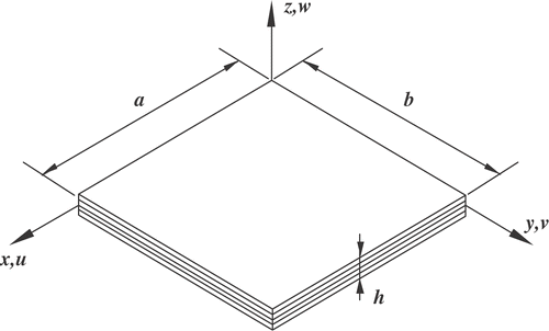
The numerical model used is a higher-order finite element laminated plate model with cubic expansion of the in-plane displacements in the thickness coordinate and constant transverse displacement through the thickness, as shown in equation (1) for the laminated plate of .
(1)
In (1), uo, vo and wo are the in-plane displacements in the x-, y-, and z-directions, t is the time variable and θx and θy are the rotations of normals to the midplane about the y-axis (anticlockwise) and x-axis (clockwise), respectively. The functions
,
,
and
are higher-order terms in the Taylor series expansion, defined also in the midplane of the plate.
Full details regarding the model development and implementation for dynamics can be found in Citation13, while its extension to account for the piezoelectric effect is described in detail in Citation1.
For each lamina () in the laminate, the constitutive equations are represented in equation (2), in the local principal material axes Citation14, Citation15.
(2)
In (2), σ and ϵ are the five component stress and deformation vectors, corresponding to the plane stress situation, e is the piezoelectric coefficient matrix (modified in order to satisfy the zero transverse normal stress condition Citation16), E and D are the electric field and electric displacement vectors, respectively, εS is the dielectric matrix, evaluated at constant strain, and QE is the elastic material coefficient matrix, evaluated at constant electric field, which is expressed in terms of the following non-dimensional elastic parameters:
(3)
where
.
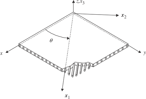
Applying a rotational transformation from the principal material axes (x1, x2, x3) to the global reference system (x, y, z), one obtains the constitutive equations in this later coordinate system Citation1.
For a laminate made of several composite and piezoelectric material laminae, the constitutive equations are obtained after integration is carried out in the laminate thickness coordinate. The equations of motion for free vibration are then obtained using the finite element method through an eight nodded serendipity plate element with nine degrees of freedom per node, corresponding to the terms in the expansion of the displacement field (1). As for the piezoelectric degrees of freedom, the electric potential variation is constant within each element's piezoelectric layers. With these considerations in mind, one arrives at the following equation of motion at the element level:
(4)
where ue, üe, φ e and
are mechanical degrees of freedom and corresponding accelerations, element electric potential variation and corresponding second time derivatives, respectively.
and
are the element mass and stiffness matrices, respectively, corresponding to pure mechanical behaviour, while
is the dielectric stiffness matrix and
is the stiffness matrix that corresponds to the coupling between the mechanical and the piezoelectric effects.
The global equilibrium equation is obtained through assembly of the element equations and, considering harmonic vibrations, one arrives at the following eigenvalue problem:
(5)
where
is the condensed global stiffness matrix, Muu is the global mass matrix and ui are the system eigenvectors corresponding to the eigenvalues λi. It should be noted that, in presence of surface electrodes, equipotential constraints are imposed on the global electric degrees of freedom before static condensation.
In order to minimise errors associated with modeling boundary conditions, we are only concerned with completely free plates, thus a shift is applied to the global stiffness matrix in order to ensure positive definiteness Citation17.
3. Parameter estimation techniques
The two proposed parameter estimation techniques are described next. Both of these techniques rely on an experimental response of the active plate structure in the form of undamped natural free vibration frequencies. The gradient based optimisation technique is an iterative procedure to solve the inverse problem, while the metamodeling technique approximates the inverse problem through an ANN metamodel.
3.1. Gradient based optimisation
In this approach, the parameter estimation technique consists in minimising the difference between the response of the physical system and the finite element numerical model that simulates the system response as a function of the elastic and piezoelectric coefficients. The response consists of a set of natural frequencies of free vibration of the plate, which are measured experimentally and then used to fit the corresponding response of the numerical model, thus determining the parameters for the best fit.
The error estimator used in this work is of weighted least squares type:
(6)
where
are the experimental eigenvalues, wi are weights used to express the confidence level in each one of the experimental eigenvalues, and I is the total number of eigenfrequencies used.
The problem is stated as the constrained minimisation of the error estimator (6), where the constraints are imposed in order to ensure positive definiteness of the constitutive elastic matrices of all materials:
(7)
In equation (7), b is the vector of design variables, whose components can be the non-dimensional elastic parameters (3) or the modified piezoelectric constants and
in (2), g is the constraint set imposed in order for each material's constitutive matrix to remain positive definite and bl and bu are the side constraints imposed on the design variables.
The numerical optimisation technique integrates methods for unconstrained problems, based on Gauss–Newton algorithm with the feasible arc interior point algorithm (FAIPA) for constrained optimisation Citation18, Citation19.
Due to the different order of magnitude of the sensitivities of the eigenfrequencies with respect to different types of possible design variables (elastic, piezoelectric and dielectric), a three phase identification procedure is used Citation1. In the first stage, only the elastic parameters associated with the base composite laminate are identified. Next, the sensors and actuators are exteriorly bonded to the surfaces of the laminate and the second phase of the identification takes place for the estimation of the elastic parameters of the piezoelectric material, in closed circuit conditions (in order to eliminate the piezoelectric effect). Finally, the third phase consists in identifying only the piezoelectric parameters, in open circuit, noting that the dielectric parameters must be determined experimentally before this third phase, using well-established procedures described in ASTM D150-98 Citation20.
3.2. Metamodeling approach
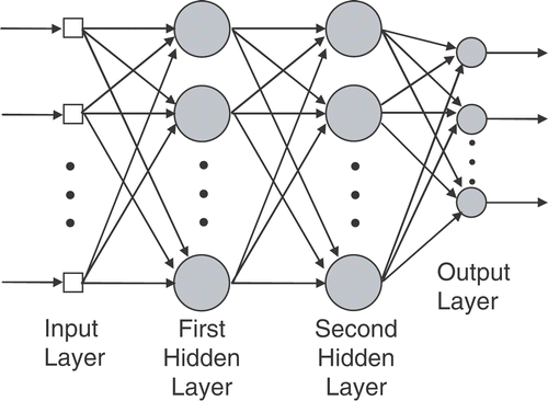
In this approach a two hidden-layer ANN is employed to model the inverse problem, as shown in . The inputs to the network are the undamped natural frequencies of free vibration of the plate and the outputs are the elastic or piezoelectric properties of the laminate. If the elastic properties are to be estimated, then the number of output neurons is six, corresponding to the six independent elastic constants. On the other hand, if the parameters to be estimated are the piezoelectric coefficients, then the number of output neurons is only two.
According to Citation21, Citation22 two hidden layers are sufficient to solve this kind of inverse problem and the number of neurons in each hidden layer was chosen to be three times the number of inputs and outputs, respectively Citation23.
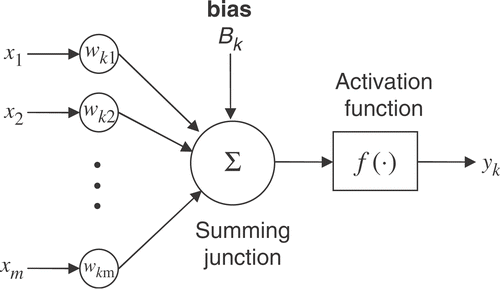
The ANN can be viewed as a non-linear mapping between the frequency space and the space defined by the material parameters to be estimated. Each neuron is the information processing unit represented in , where wkj is the weight associated to input xj of neuron k, Bk is the bias associated with the same neuron and f is the activation function of the neuron. Thus, the output of neuron k can be expressed through:
(8)
In this work, the activation functions are of the log sigmoid type for neurons in the two hidden layers and of the pure linear type for neurons in the output layer.
The output of the network can be expressed as the non-linear mapping (9), where W is a matrix of weights and biases, Y is the vector of outputs (elastic or piezoelectric parameters) and X the vector of inputs (natural frequencies)
(9)
In designing such non-linear mapping, the parameters to be adjusted are the weights and biases in matrix W. This is done through a supervised learning process by feeding the network with pairs of known inputs and corresponding target outputs, produced by the finite element numerical model, and adjusting the weights such that the network produces outputs as close as possible to the known ones. This is defined as an unconstrained minimisation problem and the Levenberg–Marquardt method was used to carry out this minimisation, using a mean square error estimator.
The training data set for the elastic constants estimation was established by using the concept of orthogonal arrays, thus reducing the full-factorial dimension of these data sets from 56 to 25. This corresponds to a L25 orthogonal array for six factors (elastic parameters) and five levels for each factor Citation24. Both inputs and outputs were normalised to unity to avoid saturation.
After training is complete, the ANN can be used to estimate the material constants, by feeding it with the experimental eigenfrequencies. As suggested before, the three phase method was also employed in this approach and the full-factorial dimension of the training data set was employed for the third phase, since there are only two parameters to estimate in this last phase (piezoelectric constants).
4. Numerical application
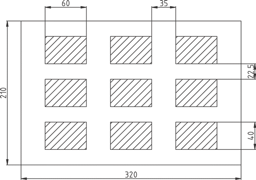
In this section, we present simulations of the two parameter estimation techniques described previously, which are denoted by FAIPA and ANN here. The plate is made of a Gr/Epoxy laminate with stacking sequence [90° , 0° , 90°] (w.r.t. horizontal). Each ply of Gr/Epoxy is 1 mm thick. The plate is instrumented with an array of nine equally spaced 60 × 40 × 1 mm PZT-4 patches bounded to the top surface of the laminate, as shown in .
Results of the simulations conducted using the first sixteen natural frequencies and a finite element mesh of 20 × 20 elements are presented in , along with the true properties of each material. All properties are layer properties given in the layer material axes, ρ represents mass per unit volume of each material and is the dielectric parameter at constant stress.
Table 1. Material properties.
In , the sixteen natural frequencies and residuals obtained after identification are presented for each one of the three identification phases. The residuals are defined as:
(10)
where
and fi are the experimental and numerical natural frequencies, respectively.
Table 2. Natural frequencies and residuals after identification.
The initial values for material parameters in the gradient based optimisation approach are presented in . These values were chosen to be in the range of typical values for each type of material.
Table 3. Initial values for material parameters (FAIPA).
As for the metamodeling approach, ANN weights and biases were randomly initialised. As a result of this random starting point, optimised weights and biases can vary substantially, although the network always predicts the material parameters correctly with very slight variations.
5. Conclusions
Two different approaches to the problem of estimating elastic and piezoelectric properties in active plate structures have been presented along with the results of a simulated identification case study.
From direct observation of the results, one can conclude that both techniques provide reasonable estimates for the parameters, although the ANN technique presents slightly higher residual levels.
Due to the low thickness to length ratio of the test specimens, the transverse shear modulus G13 and G23 are difficult to identify since the transverse shear is not noticeable.
Regarding the identification of the piezoelectric coefficients, some error propagation occurs because for phases 2 and 3 the identified results from previous phases are used, as in a real identification process. This is especially more evident for the ANN method.
In both approaches, initial values for the design parameters/weights do not influence results in a noticeable way, although this can happen if one does not use enough experimental natural frequencies. Also, when using the ANN approach, care must be taken in order to avoid overfitting by properly adjusting the size of the network.
Comparisons of execution times between the two methods show that ANN takes from about 1.2 to 2.4 times more computer time than FAIPA.
Acknowledgements
The authors thank the financial support of FCT/POCTI/FEDER, FCT/POCI (2010)/FEDER, Project POCI/EME/56316/2004, EU FP6-STREP project contract n. 013517–NMP3–CT–2005–013517, FCT/GRICES, CNPq (Brazil), FARPEJ (Brazil). The first author thanks The Technical University of Denmark.
References
- Araújo, AL, Soares, CMM, Herskovits, J, and Pedersen, P, 2002. Development of a finite element model for the identification of mechanical and piezoelectric properties through gradient optimisation and experimental vibration data, Composite Structures 58 (2002), pp. 307–318.
- Soares, CMM, Freitas, MJM, Araújo, AL, and Pedersen, P, 1993. Identification of material properties of composite plate specimens, Composite Structures 25 (1993), pp. 277–285.
- Araújo, AL, Soares, CMM, and Freitas, MJM, 1996. Characterization of material parameters of composite plate specimens using optimisation and experimental vibrational data, Composites B 27B (1996), pp. 185–191.
- Araújo, AL, Soares, CMM, Freitas, MJM, and Pedersen, P, 2000. Combined numerical-experimental model for the identification of mechanical properties of laminated structures, Composite Structures 50 (2000), pp. 363–372.
- Pedersen, P, 1999. "Identification techniques in composite laminates". In: Mota Soares, CA, Mota Soares, CM, and Freitas, MJM, eds. Mechanics of Composite Materials and Structures. Dordrecht: Kluwer Academic Publishers; 1999.
- Rikards, R, Abramovich, H, Green, T, Auzins, J, and Chate, A, 2003. Identification of elastic properties of composite laminates, Mechanics of Advanced Materials and Structures 10 (2003), pp. 335–352.
- Cunha, J, and Piranda, J, 1999. Application of model updating techniques in dynamics for the identification of elastic constants of composite materials, Composites B 30 (1999), pp. 79–85.
- Balasubramaniam, K, and Rao, NS, 1998. Inversion of composite material elastic constants from ultrasonic bulk wave phase velocity data using genetic algorithms, Composites B 29B (1998), pp. 171–180.
- Lui, GR, Ma, WB, and Han, X, 2002. An inverse procedure for determination of material constants of composite laminates using elastic waves, Computer Methods in Applied Mechanics and Engineering 191 (2002), pp. 3543–3554.
- Lui, GR, Lam, KY, and Han, X, 2002. Determination of elastic constants of anisotropic laminated plates using elastic waves and a progressive neural network, Journal of Sound and Vibration 252 (2002), pp. 239–259.
- Banks, HT, Smith, RC, and Wang, Y, 1996. Smart Material Structures – Modeling, Estimation and Control. Paris: Masson; 1996.
- Banks, HT, Smith, RC, Brown, DE, Metcalf, VL, and Silcox, RJ, 1997. The estimation of material and patch parameters in a PDE-based circular plate model, Journal of Sound and Vibration 199 (1997), pp. 777–799.
- Moita, JS, Soares, CMM, and Soares, CAM, 1999. Buckling and dynamic behaviour of laminated composite structures using a discrete higher order displacement model, Computers and Structures 73 (1999), pp. 407–423.
- Mitchell, JA, and Reddy, JN, 1995. A refined hybrid plate theory for composite laminates with piezoelectric laminae, International Journal of Solids and Structures 32 (1995), pp. 2345–2367.
- Reddy, JN, 1999. On laminated composite plates with integrated sensors and actuators, Engineering Structures 21 (1999), pp. 568–593.
- Benjeddou, A, Deü, J-F, and Letombe, S, 2002. Free vibrations of simply-supported piezoelectric adaptive plates: an exact sandwich formulation, Thin-Walled Structures 40 (2002), pp. 573–593.
- Zienkiewicz, OC, 1971. The Finite Element Method in Engineering Science. New York: McGraw Hill; 1971.
- Herskovits, J, 1998. A feasible directions interior point technique for nonlinear optimisation, Journal of Optimization Theory and Applications 99 (1998), pp. 121–146.
- Herskovits, J, Dubeux, V, Soares, CMM, and Araújo, AL, 2004. Interior point algorithms for nonlinear least squares problems, Inverse Problems in Science and Engineering 12 (2004), pp. 211–223.
- ASTM D150-98, 1999. "Standard Test Methods for AC Loss Characteristics and Permittivity (Dielectric Constant) of Solid Electrical Insulation". In: Annual Book of ASTM Standards. Vol. 10.01. West Conshohocken: American Society for Testing and Materials; 1999.
- Haykin, S, 1999. Neural Networks: A Comprehensive Foundation. New Jersey: Prentice Hall; 1999.
- Sontag, ED, 1992. Feedback stabilization using two-hidden-layer nets, IEEE Transactions on Neural Networks 3 (1992), pp. 981–990.
- Zhang, Z, and Friedrich, K, 2003. Artificial neural networks applied to polymer composites: a review, Composite Science and Technology 63 (2003), pp. 2029–2044.
- Taguchi, G, and Konish, S, 1987. Orthogonal Arrays and Linear Graphs: Tools for Quality Engineering. Dearborn: American Supplier Institute; 1987.
