Abstract
This work presents a methodology to solve transient inverse design of radiative enclosures for heating processes that require refined temperature control. The proposed methodology is applied to find the heat input to a heater located at the top of a three-dimensional enclosure that can satisfy a prescribed time-dependent temperature curve on a surface located at the base of the enclosure. The process is governed by radiative exchanges between diffuse, gray surfaces. This problem is described by an ill-conditioned system of linear equations, which is regularized by the truncated singular value decomposition (TSVD) method. The inverse analysis led to a heat input in the heater that assured, within an error less than 1.0%, both uniformity and the correct magnitude of the design surface temperature in every instant of the process.
1. Introduction
Many industrial processes, such as in the metallurgy field and the rapid thermal processing of silicon wafers, require controlled heating of materials, as has been described by Choi and Do Citation1, Huang et al. Citation2, and Balakrishnan and Edgar Citation3. Regarding the material temperature, such processes require not only uniformity but also that it follows a specified time-dependent curve. This can be achieved only by means of a carefully controlled heat flux on the surface of the processed material, as defined by the energy balance, so in fact both the temperature and heat flux are imposed. The thermal designer aims at finding the thermal conditions of the system such that these two conditions are satisfied.
In the inverse design approach, the conditions in the unconstrained elements are found directly from the two specifications on the design surface, avoiding the trial-and-error procedure of the foward design. The mathematical model allows the prescription of two conditions in some boundaries, while other boundaries are left unconstrained. For problems that involve thermal radiation heat transfer, this type of formulation is described by a Fredholm integral equation of the first kind, known to result in ill-posed problems that can be solved only by means of regularization methods (Hansen Citation4). A comprehensive review of steady state inverse design can be found in França et al. Citation5. More recently, the inverse design approach was applied to tackle transient heating processes. Ertürk et al. Citation6 employed the conjugate gradient regularization method to find the heater settings of a roll-through batch furnace to satisfy a prescribed temperature history on the design surface. França Citation7 solved a similar problem, although considering a two-dimensional enclosure and using the truncated singular value decomposition (TSVD) regularization. In an alternative approach, Daun and Howell Citation8 employed an optimization technique to find the optimal transient heater settings of a two-dimensional annealing furnace.
This article considers a transient inverse design of a three-dimensional rectangular enclosure. The objective is to find the time-dependent heat input in the heater located at the top of the enclosure so that the time-dependent temperature curve imposed on the design surface is attained. As in real furnaces, the problem incorporates the wall thermal capacities and heat losses to the outside environment. All physical properties are assumed constant, and all the surfaces that form the enclosure are gray emitters and absorbers. The energy transport is governed solely by thermal radiation, which is treated numerically through the discretization of the radiative terms of the energy equation. The resulting system of equations is expected to be ill-conditioned, since it arises from the discretization of a Fredholm integral equation of the first kind. The set of equations is solved by first relating the known temperatures and heat fluxes of the design surface elements directly to the unknown radiosities of the heater elements. This requires an iterative solution, since the effect of the remaining walls of the enclosure needs to be assumed and corrected. The ill-conditioned nature of the system is treated by means of the TSVD.
2. Physical and mathematical model
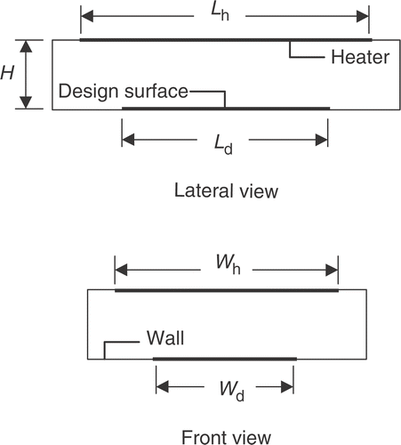
presents a schematic view of a three-dimensional radiative enclosure, which is formed by gray, diffuse surfaces. The space inside the enclosure is filled with a transparent medium, so energy is transported solely by thermal radiation exchange among the surfaces. The design surface and the heater are located on the bottom and top of the enclosure. The remainder of the enclosure is formed by walls that are isolated, albeit not ideally, from the outside. The length, width, and height of the enclosure are L, W, and H respectively.
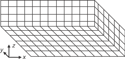
As depicted in , the enclosure is divided into finite-size square elements, Δx = Δy = Δz, to which the energy balance is applied. The elements in the design surface, heater and wall are designated by ‘jd’, ‘jh’, and ‘jw’ respectively.
Consider that each design surface element ‘jd’ has imposed a heating history of the following type:
(1)
So, the temperature is required to increase from a value of t = to for τ = 0 to t ≅ 0.99 for τ = 1.0. (The constant “4.6” assures this requirement.) The elevation in the temperature of the design surface must follow from the energy balance; that is, the increase in the internal energy of the design surface must account for heat gains and losses:
(2)
The first term of the right-hand side of equation (2) accounts for the net radiative heat transfer exchanged with the other enclosure surfaces. The negative sign arises from the convention that radiative heat out of the surface is positive. The second term accounts for heat losses to the outside, at the temperature to, where R is the equivalent thermal resistance.
Rearranging equation (2) allows finding the required radiative heat flux on the design surface at a given instant of time:
(3)
Equation (3) indicates that the heat flux to be provided to the design surface must account for both the increase in the temperature and compensate for the heat losses. Note that the transient term of equation (2) is based on the lumped capacitance model. While this model is accurate only for small temperature gradients in the interior of the material, equation (2) still holds as an illustrative, simple relation for the required heat load in a material undergoing an imposed heating history. When the temperature of the material is not uniform, it is necessary to apply a conduction analysis in the interior of the material to find the required heat load. This would complicate, although not change the essence of the inverse analysis presented here.
The radiative heat flux specified on the design surface must be supplied by the heater located along the top of the enclosure. This energy is transported by thermal radiation, which involves multiple reflections and absorptions at all the surfaces of the enclosure. The mathematical model relies on the radiative relations for enclosures (Siegel and Howell Citation9). The problem is formulated by a system of integral equations, which can be solved numerically by the discretization of the domain into finite size elements. The net radiative heat flux on a design surface element ‘jd’ is given by a balance between the radiosity and the irradiation:
(4)
The radiosity Qo,jd accounts for both emission and reflection from the design surface element. Since both the temperature and heat fluxes are specified on the design surface, the radiosity of the design surface element can be readily found from the relation:
(5)
The irradiation Qi,jd accounts for all the incident energy on the design surface element, including both emission and reflection from the other surfaces of the enclosure:
(6)
In the above equation, for example, Fjd−jh is the view factor between elements on the design surface and on the heater; Qo,jh is the radiosity of element ‘jh’ on the heater.
As stated earlier, no thermal condition has been imposed on the heater. At this point, however, it is possible to rearrange equations (4) and (6) to provide an equation for the radiosity of the heater elements:
(7)
Neglecting the thermal capacity of the heater and other losses, the heat input in the heater should equal the net radiative heat transferred to the other surfaces of the enclosure, that is:
(8)
To solve for the net radiative heat flux on a heater element ‘jh’ using equations (7) and (8), it is still necessary to find the radiosities of the wall elements, Qo,jw. It is considered here that the thermal capacity of the walls is not negligible, so they also absorb energy during the heating of the design surface. In addition, as occurs in practice, these elements are not ideally insulated, so heat losses to the outside should be also accounted for. Therefore, the usual simplification of adiabatic wall, Qr,jw = 0, is not adopted here. Instead, the radiative relations will be set in terms of the temperatures of the elements on the wall, since they will be followed and determined during every time instant of the process. In such a case, the radiosity of a wall element ‘jw’ can be found as:
(9)
The last term in equation (9) accounts for the energy that the wall element receives from another wall element, jw*, when they face each other. To find the temperature of the wall elements, it is necessary to solve the energy balance. Following the same arguments presented for the design surface elements, one obtains:
(10)
where the net radiative heat flux can be found as:
(11)
3. Solution procedure
3.1. Regularization of the system of equations
In this inverse analysis, the radiosities of the design surface elements are known from the application of equation (5). Taking the energy balance on the heater elements, equation (8), to establish a relation for their radiosities does not result in any advantage, since it also introduces their unknown heat fluxes. For this reason, the energy balance for the design surface is taken to form a system of linear equations to solve for the unknown radiosities of the heater elements, as given by equation (7). However, this system has two challenging aspects. First, with the numbers of design surface elements and of heater elements being designated by JD and JH, then the numbers of equations and of unknowns will be JD and JH, respectively. Therefore, unless JD and JH are equal, the numbers of equations and of unknowns will not be the same. Secondly, equation (7) is the discrete form of a Fredholm integral equation of the first kind (as demonstrated in França et al. Citation5), and so the system is expected to be ill-conditioned. The application of conventional methods of matrix inversion inevitably leads to a solution vector whose components present steep oscillations between positive and negative numbers, which is not physically acceptable since the radiosities must be positive numbers.
The two above difficulties can be tackled with the application of so-called regularization methods. Such methods impose additional constraints to the original problem to smooth the solution vector, although at the expense of introducing an error into the solution. Among these methods are singular value decomposition (SVD), the Tikhonov method and conjugate gradient regularization.
In this work, the TSVD was the selected method, as described in Hansen Citation4. First, the matrix A corresponding to the set of equations (7), and whose components are the view factors Fjd−jh, is singularly decomposed into three matrices:
(12)
where U and V are orthogonal matrices, and W is a diagonal matrix formed by the singular values wj. The solution vector x, which is formed by the radiosities of the heater elements, is computed by:
(13)
where JH is the number of unknowns (heating elements) and bk is the coefficient of the independent vector b.
In ill-posed problems, the singular values wj decay continuously to very small values. Since they are in the denominator of equation (13), this results in components of x with very large absolute numbers. However, the smaller the singular value wj is, the closer the corresponding vector vj is to the null-space of A. In other words, the terms related to the smaller singular values can be eliminated from equation (13) without introducing a large error to the solution. This is the principle idea of the TSVD: only the terms related to the pth largest singular values are kept on equation (13), instead of all JH terms. The solution is the vector x with the smallest norm subjected to minimum deviation |A·x}−b}}| Another important feature of the TSVD method is that it can also be applied to the case where the numbers of unknowns and equations are not the same, as will be shown in the results section.
3.2. Solution strategy
This section discuss the steps to be followed to find the time dependent heat flux distribution on the heater.
At the beginning of the process, τ = 0, the design surface and the wall are at a uniform temperature to, the same temperature as outside the enclosure. The net radiative heat flux on the design surface can be found by applying an explicit finite difference approach to the transient term of equation (3):
(14)
In the above equation,
represents the temperature of the design surface computed from equation (1) at time τ = mΔτ, where Δτ is the time step. An analytical expression for the time dependent heat flux on the design surface could be easily obtained from equations (3) and (1), but since an explicit finite difference approximation will be used for the wall elements, equation (14) was used to keep a uniform approach.
Once the heat flux and the temperature are known for each design surface element, its radiosity can be determined from equation (5). Next the radiosities of the heater elements, Qo,jh, are determined from the solution of equation (7). As discussed in the previous section, this system of equations is ill-conditioned, and is solved by the regularization method. Since the radiosities of the wall elements, Qo,jw, are unknown, an iterative approach is involved. First, Qo,jw is guessed in equation (7) to allow the computation of Qo,jh. Once Qo,jh is computed, equation (9) is applied to solve for Qo,jw. This last step requires a solution of a linear system of equations on the unknowns Qo,jw, a system that is both square and well conditioned, so it can be solved by any standard method. With the newly calculated Qo,jw, the system of equations formed by equation (7) is solved to find new values for Qo,jh. This procedure is repeated until convergence is achieved. Next, the net radiative heat flux on the heater, Qr,jh, is determined from equation (8), since all the radiosities are now known.
Note that the heat flux on the heater elements determined according to the aforesaid is related to time step m. At this time step, the design surface and wall temperatures are also known. Since one thermal condition is known for each boundary of the system, a forward analysis can then be applied to find the actual net radiative heat flux design surface element, which is not exactly the same as the imposed one due to the regularization. The actual temperature of the design surface in the next time step, m + 1, is found from the application of equation (14) using the actual heat flux.
To determine the wall temperature for time step m + 1, equation (11) is first applied to find the net radiative heat flux on each wall element at time step m, since all the radiosities are known. Then, the temperature of the wall elements at time step m + 1 can be determined from the application of an explicit finite difference approach to the transient term of equation (10):
(15)
Finding the heat flux on the heater for the next time step, m + 1, only requires that the procedure outlined above is repeated. A time marching solution therefore has been established.
3.3. Verification of the solution
The application of the TSVD regularization inevitably introduces an error to the solution, since only p < JH terms are kept in the series of equation (13). The accuracy of the solution can be assessed by comparing both the heat flux and the temperature obtained from the inverse solution with the prescribed values for the temperature, equation (1) and heat flux, equation (3):
(16)
(17)
4. Results and discussion
The case considered in this work consists of a three-dimensional enclosure as shown in the schematic of . The initial dimensionless temperature of the enclosure, the same as the outside temperature, is to = 0.375. The total hemispherical emissivities of the design surface, of the heater, and of the walls are εd = 0.5, εh = 0.8 and εw = 0.8, respectively. The thermal capacities of the design surface and of the wall are Cd = 20 and Cw = 4. As a common design procedure, the thermal resistance to the outside, R, is set so that the maximum heat flux lost to the outside is about 2.5% of the maximum heat flux in the design surface, giving R = 0.4.
The aspect ratio of the enclosure base is W/L = 0.8. The selection of the other dimensions of the enclosure requires a few considerations. First, the design surface ought not to cover the entire extension of the base, since the portions close to the corners are mainly affected by the side wall conditions, not the heater. Therefore, the design surface dimensions are taken as Ld/L = 0.6 and Wd/L = 0.4. In addition, to reduce the effect of the side walls, previous work (França et al. Citation5) has shown the advantage of selecting heaters with larger dimensions than those of the design surface. For this reason, the heater is selected to cover the entire top surface of the enclosure: Lh/L = 1.0 and Wh/L = 0.8.
One consequence of this choice is that the number of equal-area elements on the design surface and on the heater (JD and JH, respectively) are not the same. Taking the advantage of the symmetry (that is, only a quarter of the domain needs to be solved: 0 ≤ x/L ≤ 0.5, 0 ≤ y/L ≤ 0.4), and selecting a grid size of Δx/L = 1/30, one finds JD = 54 and JH = 135. Thus, the system of equations formed by equation (7) will have JD = 54 equations and JH = 135 unknowns.
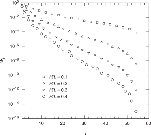
To select the enclosure height, it is instructive to inspect the characteristics of the system of equations formed by equation (7). presents the SVD of the system of equations for H/L = 0.1, 0.2, 0.3, and 0.4. The number of singular values is equal to the number of unknowns, JH = 135. Since the number of equations is JD = 54, all singular values for j ≥ 55 are null, and are not shown. As seen, in all cases the singular values wj decay continually with index j, which is typical of ill-posed problems. In addition, the larger the enclosure height, the more abrupt is the decaying of the singular values. This indicates that enclosures with relatively large heights make it more difficult to invert the system of equations, and therefore are less interesting design choices. In addition, considering that an enclosure with H/L = 0.1 might be too short, the selected height is H/L = 0.2.
Now that the system is completely defined, the procedures outlined previously is employed to find the required heat input in the heater. This problem involves the TSVD regularization of matrix A, that is, the selection of different values of the regularization parameter p to be applied in equation (13). Then, the obtained solution for each p can be compared in terms of their adequacy (physical and practical constraints) and accuracy (the error in the design surface temperature).
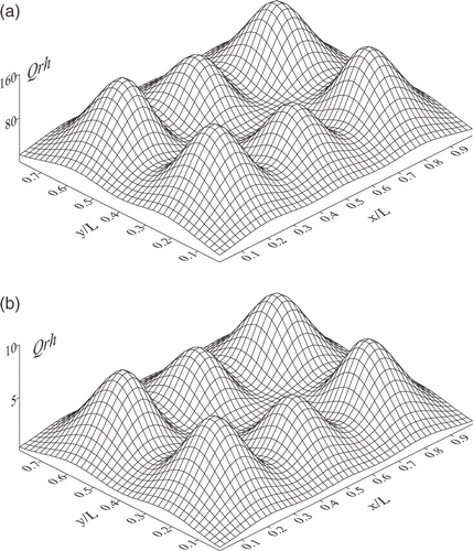
present the required heat flux distribution on the heater at the initial instant, τ = 0, for different regularization parameters, p = 4, 6 and 8. In other words, these solutions were obtained by keeping only the first four, six, or eight terms (corresponding to the largest singular values) of the series defined of equation (13), instead of using all the JH terms. It was verified that selecting p larger than 8 led to negative heat fluxes on some of the heater elements (not a practical solution) or to negative radiosities (not a physically possible solution). As seen in the figures, the three solutions present the oscillations that often characterize such inverse problems. These oscillations are in fact reminiscent of the steep oscillations of the exact solution. As the regularization parameter is reduced, the steep oscillations are increasingly smoothed out. Once the regularization parameter is selected, the procedure outlined in section 3.2 was applied to determine the heat flux required to the heater during the transient process. For that, a time step of Δτ = 0.001 was adopted.
Figure 4. Heat flux distributions in the heater for different regularization parameters (τ = 0): (a) p = 4, (b) p = 6, and (c) p = 8.
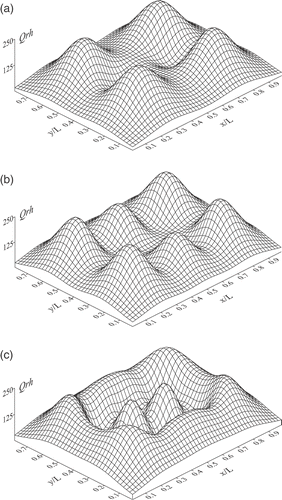
The different solutions presented in show that more than one solution can be proposed for an inverse design problem. However, each regularized solution can only satisfy the original problem with some error. In section 3.3, two errors have been defined: one based on the heat flux and the other based on the temperature of the design surface. Both errors have been computed for the three regularizations ( p = 4, 6, and 8) for different instants of time, and are presented in . As expected, the results show that the smaller the regularization parameter p, the larger are the errors for the heat flux and temperature distributions on the design surface. It is interesting to note that the errors for the heat flux and temperature present an opposite behavior with time. The error in the heat flux is maximum in the beginning of the process, decreases steadily up to τ ≅ 1.0, and then shows a slight increase with time. The error in the temperature, on the other hand, starts with a smaller value than that of the heat flux, increases to a maximum for a time less than τ = 0.5, and then remains nearly constant with time.
Figure 5. Maximum errors of the inverse solution during the heating process for different regularization parameters: p = 4, 6, and 8.
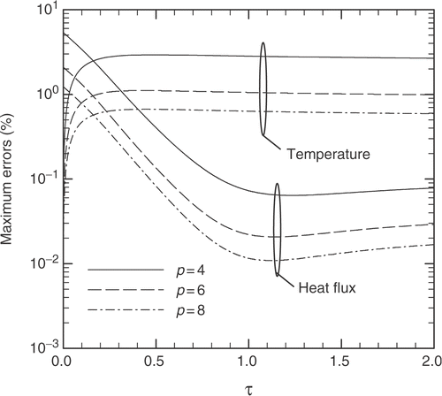
It should be pointed out that, for the thermal process, it is the error in the temperature that matters the most, since it is the temperature history that is in fact imposed on the design surface; the heat flux is only the means for it to occur. On comparing the three solutions, for p = 4, 6, and 8, if a maximum error of 1.0% is imposed to the temperature, then the solution for p = 4 is not satisfactory. The solution for p = 8 presents the smallest error, but it was observed that, for more advanced times, it led to negative heat fluxes in some elements of the heater elements, which is not a practical solution. So the solution for p = 6 remains, and satisfies all the imposed criteria: accuracy and practicality.
and show the required heat flux on the heater for an intermediate time, τ = 0.1, and for a sufficiently long time, τ→∞, when the temperatures in the enclosure reach steady state. Comparing , and and , all solutions obtained with p = 6, the shape of the heat flux distribution did not change considerably, while only the intensity of the heat flux varied (note the change of scale between them). For long heating periods, τ →∞, even though the temperature of the design surface is no longer required to increase, the heater must still provide some heat to compensate the heat losses to the outside, as shown in .
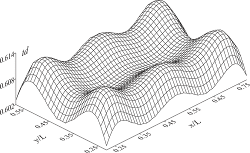
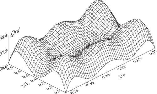
and show the temperature and the heat fluxes distributions on the design surface for instant of time τ = 0.1. At this instant of time, the required design surface temperature, according to equation (1), is tjd = 0.605. The temperature obtained from the inverse solution remained close to the value for the entire extension of the design surface. Similarly, shows that for τ = 0.1, the heat flux distribution on the design surface also remained close to the prescribed value, Qr,jd = −36.9. Both figures also show that the larger deviation occurs at the edges of the design surface, especially in the corners, where the effect of the side walls become important.
5. Conclusions
This work considered a transient inverse boundary design where the time-dependent heat input on the heater was determined to satisfy a specified time-dependent temperature curve. The numerical discretization of the problem led to an ill-conditioned system of equations as is usual in the inverse design approach, which was solved with the aid of the TSVD regularization method.
The proposed methodology involved a time marching solution, setting a system of equations that related the design surface elements directly to the heater elements, calculating the remaining terms, that is, the radiosities of the wall elements from the conditions of the previous iterative step. This procedure allowed the application of the regularization to a reduced system of equations.
The example problem consisted of a three-dimensional radiative enclosure formed by gray, diffuse surfaces. During the heating of the design surface, the energy consumed by the other walls of the enclosure as well as heat losses to the outside of the enclosure were taken into account to find the necessary heat input in the heater. As usual for inverse design analysis, different approximate solutions were obtained according to the choice of the TSVD regularization parameter. Although the optimum value of the regularized parameter will vary for different applications, the choice of the optimum value is usually of simple implementation, since selecting each parameter will lead to a solution that can be promptly evaluated according to a given criteria. The selected solution was capable of providing, with an error of less than 1.0%, both uniformity and the correct magnitude of the design surface temperature during the entire heating process. Solving such a problem would be impractical with the forward approach, since it would require a cumbersome trial-and-error solution for each instant of time.
| Nomenclature | ||
| A | = | = matrix of coefficients |
| c | = | = thermal capacity per unit of area, J/(K m2) |
| C | = | = dimensionless thermal capacity, c/(σTf |
| F | = | = view factor |
| H | = | = height (m) |
| j | = | = singular value index |
| jd | = | = design surface element index |
| jh | = | = heater surface element index |
| jw | = | = wall surface element index |
| JD | = | = number of design surface elements |
| JH | = | = number of heating elements |
| JW | = | = number of wall elements |
| L | = | = length (m) |
| Q | = | = dimensionless heat flux, q/(σ |
| q | = | = heat flux (W m−2) |
| r | = | = equivalent thermal resistance (K W−1) |
| R | = | = dimensionless thermal resistance, rσ |
| t | = | = dimensionless temperature, T/Tref |
| T | = | = temperature (K) |
| x | = | = position along the enclosure length |
| y | = | = position along the enclosure width |
| z | = | = position along the enclosure width |
| w | = | = singular values of matrix A |
| W | = | = width (m) |
| Greek symbols | ||
| ε | = | = emissivity |
| τ | = | = dimensionless time, T/Tf |
| T | = | = time (s) |
| Tf | = | = time required for the design surface to reach 99% of the final temperature (s) |
| Subscripts/Superscripts | ||
| d | = | = design surface |
| h | = | = heater |
| i | = | = irradiation |
| j | = | = counter |
| k | = | = counter |
| m | = | = time step |
| o | = | = radiosity; outside (initial) temperature |
| r | = | = net radiative heat flux |
| w | = | = wall |
Acknowledgment
The first author thanks CAPES (Brazil) for the support under the program CAPES/UT-AUSTIN, No. 06/02.
References
- Choi, JH, and Do, HM, 2001. A learning approach of wafer temperature control in a rapid thermal processing system, IEEE Transactions on Semi-conductor Manufacturing 14 (2001), pp. 1–10.
- Huang, CJ, Yu, CC, and Shen, SH, 2000. Selection of measurement locations for the control of rapid thermal processor, Automatica 36 (2000), pp. 705–715.
- Balakrishnan, KS, and Edgar, TF, 2000. Model-based control in rapid thermal processing, Thin Solid Films 365 (2000), pp. 322–333.
- Hansen, PC, 1990. Truncated SVD solutions to discrete ill-posed problems with ill-determined numerical rank, SIAM Journal of Science Statistical Computation 11 (1990), pp. 503–518.
- França, F, Howell, J, Ezekoye, O, and Morales, JC, 2003. "Inverse design of thermal systems". In: Hartnett, J.P., and Irvine, J.P., eds. Advances in Heat Transfer. Vol. 36. San Diego: Academic Press; 2003. pp. 1–110.
- Ertürk, H, Ezekoye, OA, and Howell, JR, 2002. The application of an inverse formulation in the design of boundary conditions for transient radiant enclosures, Journal of Heat Transfer 124 (2002), pp. 1095–1102.
- França, FHR, 2003. "Transient inverse design of radiative enclosures". In: Proceeding of the 17th International Congress of Mechanical Engineering. São Paulo, Brazil. 2003.
- Daun, KJ, and Howell, JR, 2004. "Optimization of heater settings to provide spatially-uniform transient heating in manufacturing processes involving radiant heating". In: Proceeding of the Inverse Problems and Optimization Symposium. Rio de Janeiro, Brazil. 2004.
- Siegel, R, and Howell, JR, 2002. Thermal Radiation Heat Transfer. New York: Taylor and Francis; 2002.
