Abstract
In this article, a new method for determination of elastoplastic properties from an indentation loading curve is proposed. Mathematical model, based on deformation theory, leads to quasi-static elastoplastic contact problem, given by the monotonically increasing values αi>0 of the indentation depth. The identification problem is formulated as an inverse problem of determining the stress–strain curve from an experimentally given indentation curve
. The inversion method is based on the parameterization of the stress–strain curve, according to the discrete values of the indentation depth, and uses only a priori information as monotonicity of the unknown function
. It is shown that the ill-conditionedness of the identification problems depends on the state discretization parameter Δei. An algorithm of optimal selection of state discretization parameters is proposed as a new regularization scheme. Numerical examples with noise free and noisy data illustrate applicability and high accuracy of the proposed method.
1. Introduction
Spherical indentation testing is one of extensively used experimental methods to measure the hardness of metal and polymer materials. The objective is usually to analyze the indentation curve as dependent on the size of the sample (indent) and indenter relative to the material length parameters, strain hardening, and yield stress to modulus ratio. The idea of relating the mechanical properties of deformable materials to their hardness was first given in Citation10. By using the method of characteristics for hyperbolic equations, he has found a relationship between the Brinell hardness , and the yield stress:
, for a spherically symmetric indentation hardness test (here and below P > 0 is the measured loading force, R > 0 is the radius of a spherical indenter and α > 0 is the indentation depth). However, in this model curvature of a contactable surface was ignored, and the problem was considered for a perfectly plastic material. Subsequently, the relationship between hardness as measured data and stress–strain behavior in the regime of “large” indents have been established in Citation12, Citation13, Citation21. Later technological advances and the need to find experimentally unmeasurable material properties by using measurable one on a small scale, led to an increasing interest in the development of new methods. Most of these methods may be divided into two groups. The first group contains various plasticity theories and models that can adequately describe spherical indentation testing. Reformulating gradient plasticity theory Fleck and Hutchinson Citation4 proposed generalization of the classical J2 flow and deformation theories. Solutions of basic problems show that, when stressing is nearly proportional, as the case of spherical indentation is, the new plasticity models predict qualitatively similar behavior to the J2 flow and deformation theories. Wei and Hutchinson Citation23 demonstrated recent trends in micron scale indentation and comparative analysis of existing plasticity models. Comparing all the plasticity models used for the spherical indentation, Budiansky Citation2 and Fleck and Hutchinson Citation4 concluded that the deformation theory version of J2 theory is used rather than the flow theory version not only because it is easier to implement numerically, but also because it gives essentially identical predictions to the flow theory, when stressing is nearly proportional (simple loading). In the second group, various analytical and numerical methods have been developed to extract elastoplastic properties of deformable materials from a measured spherical indentation loading curve (see Citation17, Citation20 and references therein). A study to extract the plastic properties of power hardening engineering materials from spherical indentation loading curve have also been given in Citation3. The results obtained here show that the identification/inverse problems related to determination of the elastoplastic properties of materials based on indentation tests, have ill-conditioned nature. For near linear hardening materials, numerical relationships between material properties and indentation responses have been obtained in Citation18–19. A utilization of connection between the indentation curve
and other mechanical properties, in particular Brinell Hardness, were given in Citation1,Citation16.
Within the framework of the J2-deformation theory of plasticity, the mathematical theory of inverse problems related to determination of elastoplastic properties from an indentation loading curve has been formulated by the author Citation5–6. The analysis given in Citation6 and based on the parametrization of the stress–strain curve, shows how the inverse problem becomes an ill-conditioned one, by increasing the value α > 0 of the indentation depth. Taking into account this analysis, a new regularization algorithm – an optimal selection of the indentation parameters i>0 – was proposed. This algorithm also allows to solve an inverse problem of determining the relationship σi=σ(ei), by using a limited number of measured data ,
Citation7.
In this article, an inversion method to extract the elastoplastic properties of engineering materials from the measured spherical indentation (loading) curve is proposed. In order to make the proposed method applicable to wide material behaviors, with respect to the hardening properties of the material it is only assumed that the relationship σi=σ(ei) is a monotone increasing and concave curve. Such a model includes wide hardening relations, in particular power hardening, linear and piecewise linear hardening ones. Section 2 involves the mathematical model of an axisymmetric spherical indentation and analysis of the relationship σi=σ(ei). Then within the framework of this model, formulation of the inverse problem of determining the stress–strain curve σi=σ(ei) from the measured indentation curve
is defined. Section 3 contains an ill-conditionedness analysis of the inverse problem. Linearization of the forward problem and convergence of solution are given in section 4. Computational framework of the forward problem with the remeshing algorithm are presented in section 5. In section 6, a parametrization of the inverse problem and the inversion algorithm are discussed. An example related to the ill-conditionedness of the inverse problem and an algorithm of optimal selection of the state discretization parameters and relaxation of monotonicity condition for slopes, are also given in this section. Section 7 contains computational results for different engineering materials with exact and noisy data
to show applicability and accuracy of the presented inversion method. The final section 8 summarizes the main contributions made by the presented methodology. Presented numerical results show that the inversion method given in this article allows to determine with high accuracy the parameterized curve σi=σ(ei) from the spherical indentation loading curve for different engineering materials.
2. The mathematical model
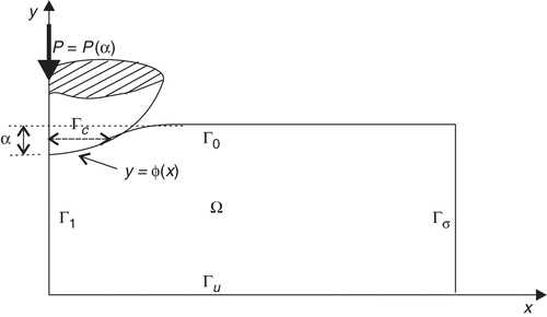
Let the rigid spherical indenter be loaded with a normal loading force , into an axially symmetric homogeneous body (sample) occupying the domain Ω×[0, 2π], in the negative y-axis direction, as shown in . The uniaxial quasi-static indentation process is simulated by monotonically increasing the value α > 0 of the indentation depth. It is assumed that the indentation process is carried out without unloading, moment, and friction. For a given value α∈(0, α*) of the indentation depth, the quasi-static axisymmetric indentation process can be modeled by the following contact problem.
Find the displacement field u(x, y)=(u1(x, y), u2(x, y)) from the solution of the unilateral problem
(1)
(2)
(3)
(4)
(5)
Here
, lx, ly >0,
,
,
, and
is the surface of the spherical indenter, with the radius r0.
The relationship between the components of strain and stress tensors is as follows:
(6)
where
the components of deformation, and
(7)
λ, μ >0 are Lame constants, E > 0 is an elasticity modulus, ν is the Poisson coefficient and G=μ is the modulus of rigidity.
The system of Lame equations (1) represents an equilibrium equations for an axially symmetric body, in the cylindrical coordinates (r, z):=(x, y), within the range of J2-deformation theory of plasticity, where strain and displacements are assumed to be small. As shown in experimental and theoretical studies (see Citation2, Citation4, Citation22 and references therein), the deformation theory provides a highly accurate approximation to the flow theory solution, when proportional or nearly proportional stressing occurs throughout the deformable body. Hence in the case of simple loading, i.e., proportional stressing, which holds for the spherical indentation without moment, J2-deformation theory of plasticity is used due to its simplicity in numerical simulations. Furthermore, in conventional physical model of spherical indentation Citation4, Citation17, Citation18, Citation22, the friction between the indenter and the indented material has a negligible effect on the indentation curve and for this reason the contact on the common surface between the indenter and the sample can be assumed frictionless. Since an indentation test is nondestructive one (shallow indentation) and can be applied both to small samples or to fabricated machine and structural elements, the above physical model is used for large class of pure and alloyed engineering materials Citation2–4, Citation17, Citation19, Citation20.
It is assumed that an axisymmetric sample lies on a substrate without friction, as conditions (5) show. Furthermore, the symmetry of the sample implies the boundary conditions (4). On the part of the boundary Γσ, beyond on the contact, the “free boundary conditions” (3) are given. The contact conditions (2), in the form of inequality, means that the contact zone
, depending on the value α > 0 of the indentation depth, is also unknown and need to be defined.
According to the J2-deformation theory, the stress–strain relationship is assumed to be in the following form ():
(8)
where
, is the strain intensity. The function
is assumed to be a monotone increasing concave one. The plasticity function g=g(ξ),
is assumed to be piecewise differentiable and satisfies the following conditions Citation14:
(9)
The case g(ξ)=0, ξ∈[0, ξ0] and
corresponds to pure elastic deformations.
The stress–strain relationship (8), which describes the elastoplastic behavior of a wide range of engineering materials, has been used in our analysis. Note that the power law description
(10)
is also widely used to approximate the plastic behavior of metal materials Citation3,Citation18, Citation23, corresponds to the power hardening materials for which the stress–strain relation is given by the Ramberg–Osgood curve
Here κ∈[0,1] is a strain hardening exponent. The cases g(ξ)=0 and
in (8) correspond to pure elastic (κ = 1) and perfectly plastic (κ = 0) materials, respectively.
The inverse problem consists of identifying the stress–strain curve , given by (8), from the measured spherical indentation loading curve
, α∈(0, αK), during the quasi-static indentation process. Accordingly, the unilateral boundary value problems (1–5) is defined to be a forward problem.
Note that indeed the indentation curve consists of loading and unloading parts. In the considered model, we use only the loading of the part indentation curve, since the Ramberg–Osgood type of materials are considered. This, in particular, means that the residual penetration depth α∈(0, αK) and loading force
should be used as a given data in the considered inverse problem. The unloading solution can be generated numerically from the solution corresponding to pure elastic case (for details of such indentation morphology, see Citation16, Citation17).
In the considered model, the Poisson coefficient ν∈(0, 0.5) is assumed to be known and has been taken ν = 0.3. Hence, in the case of pure elastic deformations ((ei≤e0)) one needs to determine the elasticity limit e0 > 0, and in the case of plastic deformations (ei≥e0) the plasticity function g=g(ξ) needs to be identified. The elasticity limit e0 > 0 will be determined by a special algorithm. Here and further it is assumed that the indentation interval (0, α0), α0 <αK corresponds to pure elastic deformations.
3. Analysis of the inverse problem
The identification/inverse problem of determining the hardening behavior from the measured spherical indentation loading curve is a complicated nonlinear process, which deals with elastoplastic material behavior. Evidently, no analytical solution for indentation response is available. In addition to all difficulties, the inverse problem arising here is an ill-conditioned one. To demonstrate this main distinguished feature, let us reformulate the inverse problem as the following nonlinear operator equation
(11)
Here Σ ={σi(ei)} is the set of monotone increasing concave functions (stress–strain curves), defined on (0, eM), and
is the set of monotone increasing convex functions (indentation loading curves), defined on (0, αK). To find out the structure of operator
, one needs to take into account that for each value α∈(0, αK) of the indentation depth, the theoretical value Pα:=Pα(σi) of the indentation loading force is defined as follows:
(12)
where the function u=u[σi] under the integral is the solution of the contact problem (1–5), corresponding to the unknown function σi=σi(ei), i.e. the unknown parameters E, e0 and g(ξ). Comparing the right hand side of (12) with (11), one can see that for each α > 0 the operator
represents an integral operator. Thus for each step of the quasi-static indentation, the inverse problem can be reformulated as the following nonlinear integral equation:
(13)
It is well known that the integral operator given by (12) is a continuous compact operator in the class L2 of square integrable functions. On the other hand, due to Tikhonov's lemma Citation22, the class of monotone increasing and uniformly bounded functions is compact in the class L2. Thus the inverse problem (11) has a unique solution in the class Σ, for each noise free data
. However, this problem is not well conditioned in the sense of Hadamard, due to sensitivity of the solution with respect to the measured data
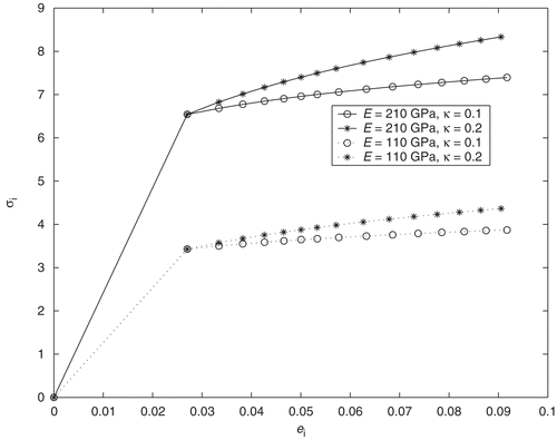
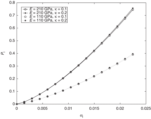
, as shown in Citation6. To show the nature of this ill-conditionedness in the case of power hardening materials, the following computational experiment has been realized for two types (rigid and soft) of materials (E1=210 GPa; E2=110 GPa) with different power hardening parameters (κ1=0.1; κ2=0.2). The stress–strain curves, given by (10), of these materials are plotted in (in all cases e0=0.027). The corresponding theoretical values of the indentation loading curves P=P(α), α∈(0, αK), has been obtained from the numerical solution of contact problems (1–5). The results, plotted in , show that the inverse problem is most sensitive when the tested materials obey the same linear hardening behavior, but different hardening parameters. Thus, for the first type of materials (with E1=210 GPa, and κ1 =0.1, κ2 =0.2) the maximum relative difference in the value of the loading force is
P(α); E1, κ1)| is
, while maximum relative difference
in the stress–strain curves is
. The same results have been obtained for the second type of materials (with E2=110 GPa, κ1 =0.1 and
):
, while
.
These results show that the indentation curves corresponding to different power hardening materials, with the same modulus of elasticity E and different power hardening parameters κ1≠κ2, may not be distinguishable. For these materials, the inverse problem (11) is most sensitive: small perturbations in the right hand side leads to essential deviations in the values of the function σi=σi(ei).
The above analysis can also be obtained from equation (13), rewriting it for pure elastic and plastic deformations, separately. Indeed, due to homogeneity of equation (1) and the Neumann boundary conditions (2–5) with respect to the elasticity modulus E > 0, by using (6) and (7) in (13), and taking into account g(ξ)=0, we get
(14)
This formula shows that the unknown elasticity modulus E > 0 can be found explicitly
by solving the contact problems (1–5) for E = 1. Here
(15)
and u=u(x, y) is the solution of the contact problems (1–5) for E = 1. Hence for pure elastic deformations the inverse problem (13) is well conditioned, and the elasticity modulus can be determined explicitly. In the case of plastic deformations (ei> e0) the inverse problem with respect to the plasticity function g=g(ξ) can be formulated as the following nonlinear boundary integral equation
(16)
where the function u=u[E, g] under the integral is the solution of problems (1–5), corresponding to E and g=g(ξ).
The operator/integral equation forms (11), (14), and (13) of the inverse problem are convenient only for its analysis, but not for subsequent numerical solution, since due to measurement errors in the given data exact fulfillment of these equations is not possible. We introduce the auxiliary functional
(17)
and define a quasisolution Citation11, Citation22 of the inverse problem, according to Citation4 as follows:
(18)
An existence of a quasisolution is proved in Citation5.
4. Analysis of the forward problem: linearization and convergence
Multiplying the first equation by u1(x, y) and the second one by u2(x, y), and applying the Green formula, we define the weak u∈V solution of the nonlinear unilateral problems (1–5) as a solution u∈V of the following variational inequality
(19)
Here
(20)
is the nonlinear form and
is the closed convex set of admissible displacements,
is the subspace of the Sobolev space H1(Ω) of vector functions u(x, y) Citation15. We take into account the axially symmetricity of the problem and define the H1-norm as follows:
As it follows from the general theory of variational inequalities for monotone potential operators Citation6, Citation15, the variational inequality (19) has a unique solution u∈V, if conditions (9) hold.
We will denote the nonlinear functional (20) by a(u;u,v):=(Au, v) to show the dependence of the nonlinear terms on the function u=u(x, y). For ei(u)≤e0 the nonlinear functional a(u;u,v) becomes the bilinear one, and we will denote it by
(21)
As it was noted above, the variational problem (19) is nonlinear not only due to the presence of the plasticity function
, but also, in the sense that for each value α > 0 of the penetration depth, the contact zone
is unknown, and needs to be also determined. For this reason, we will organize here two iteration procedures in order to linearize the nonlinear forward problem: first, with respect to the unknown contact zone, and the second one, with respect to the plasticity function
.
Let us assume that the unknown contact zone Γc(α) is found by any way. Then the unilateral boundary conditions (2) will be separated into following the mixed boundary conditions:
(22)
(23)
In this case, the unilateral problems (1–5) will be transformed to the mixed boundary value problems (1), (3–5), (22–23), which in subsequent will be defined as the problem (Pc). The solution of this problem will be denoted by u(x,y):=u[x, y; Γc].
Let now be a given perturbed contact domain:
. Then, either
(i.e.,
), or
(i.e.,
). Since
is assumed to be given, the unilateral boundary conditions (2) will be seperated into the following mixed boundary conditions:
(24)
(25)
The unique solution of the mixed boundary value problems (1), (3–5), (24–25) (in subsequent, the problem
), corresponding to the perturbed contact zone
, will be denoted by
. Note that depending on
or
the inequalities (2) change signs, accordingly. This result, obtained in Citation8, will be used below, in the remeshing algorithm.
In pure elastic case (g(ξ)=0), the following result shows a relationship between the solutions u=u(x, y) and of the problems (Pc) and
.
LEMMA 1
Let v1(x, y) = 0, x∈Γ1} be solutions of the mixed problems (Pc) and
, corresponding to true Γc⊂Γ0 and perturbed
contact domains, respectively. Assume that g(ξ)=0, and
. Then the following assertions hold:
(a) if then
(26)
(b) if then
(27)
Proof
Let us first assume that and
. Evidently the solutions ⟨u(x, y);Γc⟩ and
of problems (P1) and
satisfy the following integral identities, respectively
Assuming that
, from these integral identities we obtain
According to the boundary conditions (22) and (24)
. This implies (26).
The second integral identity (27) can be obtained by the same way. ▪
By using the coercivity of the bilinear form a(u, v) on the left hand side and applying the Cauchy inequality with the mean value theorem on the right hand side of (26) and (27), we have the following
COROLLARY 1
Let conditions of Lemma 1 hold and σ22(u)∈H0(Γ0). Then the following estimates hold:
(a) if then
where
(b) if then
where
This result suggests an idea of approximation of the variational inequality (19) by the corresponding integral identities of types (26) and (27).
THEOREM 1
Let g(ξ)=0 and σ22(u)∈H0(Γ0). Assume that ,
, meas
, ∀m, be a sequence of a priori given contact domains. Denote by
,
the sequence of corresponding solutions of problems
:
If the sequence
converges to Γc, in the sense that
, as m→∞, then the sequence of solutions
converges to the solution
of the problem (Pc), in the norm of the space H1(Ω).
Proof
Due to Corollary 1, the difference of solutions u(x,y):=u[x, y; Γc] and can be estimated as follows:
(28)
(29)
depending on
or
, accordingly. Here
As
, the right hand sides of inequalities (28) and (29) tend to zero, which means
, as m→∞. This implies the proof. ▪
Consider now the case g(ξ)>0. Taking into account the nonlinear term g=g(ei(u)) in (20), we rewrite it as follows
(30)
Then we linearize the nonlinear problem (Pc) by Kachanov's method Citation14:
(31)
We define this mixed problem as the problem (Pn). Taking into account (30), the potential of this problem can be defined as follows Citation9:
where
are the coefficients from n − 1-th iteration (see (7)). If conditions (9) hold, then the rate of convergence of the sequence of solutions
of problems (Pn), to the solution
of the problem (Pc) can be estimated via the monotone decreasing convergent sequence of potentials {Π0(u(n))} as follows (see, Theorem 2 Citation9):
(32)
Let us now substitute
in (31) and denote it by
, the solution of the obtained problem [the problem
. Then combining Theorem 1 and estimate (32) we have the following convergence
THEOREM 2
Let conditions of Theorem 1 hold and the plasticity function g=g(ξ) satisfies conditions (9). Then the sequence of solutions of problems
converges to the solution
of the problem (Pc) in H1-norm, as m, n→∞.
Proof
If u=u[x, y;Γc] is the solution of the nonlinear problem (Pc), the difference can be estimated as follows:
Here un=un[x, y;Γc] is the solution of the linearized problem (31) [the problem (Pn)]. The first norm on the right hand side tends to zero as n→∞, due to (32). The second norm also tends to zero as m→∞, according to Theorem 1. Hence
, as m, n→∞, and we obtain the proof. ▪
5. The remeshing algorithm for the forward problem
Since an accuracy of the numerical solution of the inverse problem highly depends on the accuracy of the corresponding forward problem solution, one needs to solve the forward problem effectively on an acceptable finite-element mesh. As was noted above, the main difficulty in solving the forward problem is the determination of the unknown contact zone Γc(α), on each step of indentation.
The above linearizations permit one to construct an iteration procedure for the considered indentation problem. Consider the sequence ,
, of perturbed contact zones. Then for a given
one needs to solve the linearized forward problem
.
For each α∈(0, αK), the iteration scheme for the forward problem (Pc) is as follows:
| i. | For a given α01 < α0 (pure elastic case: g(ei)=0), choose an initial iteration | ||||
| ii. | Repeat the step (I) for m + 1 until the fulfillment of the condition
| ||||
| iii. | For a given α1 = α0+ Δα (g(ei)≠0), choose an initial iteration | ||||
| iv. | Use the approximate solution | ||||
| v. | Continue the steps (III)–(IV) for the next values αp = αp−1+ Δα, p=2,3, …,K. | ||||
Finite-element discretization of the linearized forward problems is performed by using linear Lagrange type of triangle elements. Due to the linearity of the interpolant uI(x, y) of the function u(x, y), the deformation intensity
will be a constant for each finite element. For a given value αk>0 of the indentation depth, the maximal value of the deformation intensity
for all finite elements Δh⊂Ω will be denoted by
, where the index p=1, 2, 3,… denotes the number of deformation states, corresponding to the parameter αp. Evidently, for α =α0 the value e0=maxΔhei(u) is an elasticity limit.
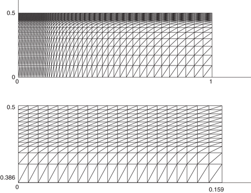
The first part of the computational experiments was related to the optimization of the finite-element mesh used for the quasi-static indentation problem, since a piecewise uniform finite-element scheme may not converge at all if the fine mesh step is not sufficiently small in relation to the coarse mesh step. For this reason, the mesh convergence study was first performed in order to determine an adequate number of nodes and elements in the sample Ω =[0,1]× [0, 0.5] cm. This is done by running different discrete models with increasing number of finite elements until the difference between contact pressure corresponding to two consecutive mesh models becomes negligible. Finally, the piecewise uniform optimal mesh with the parameters Nx = 50, Ny = 20 (the number of mesh points on the intervals [0, lx] and [0, ly], respectively), shown in upper , is constructed. The uniform fine mesh with the mesh steps , defined in the strip
(lower ), contains the admissible contact zone, and is localized in a small area under the indenter, where, as expected, the maximum stress magnitudes arise. Here
is the mesh point corresponding to the boundary of the contact zone. The uniform fine part was continued to the right along the boundary Γ0 for two mesh points
, k = 1, 2, so that the boundary of the contact domain always remains in the fine mesh:
. In all remeshing process, the number of mesh points of the fine mesh remains constant. Outside of the strip Ω1 the coarse mesh, with slowly increasing mesh steps
is defined. Here Np is the number of mesh points in the interval (ac, lx), correspondingly. However, once the contact zone for a given value of penetration depth is unknown, use any of fixed mesh in the best case may only localize the unknown boundary
of the contact zone Γc(α) between two neighboring mesh points. At the same time, as shown in Citation8, any perturbation of the parameter a_c > 0 even for one mesh step, can deviate from values of the normal component σ22 of stress on neighborhood of the contact zone. For this reason, the above iteration process will be used with the remeshing (regridding) algorithm described below. The main distinguished feature of this algorithm is that the total number of mesh points remain constant, which permits to deal with the stiffness matrix with constant dimension on each iteration
, m=1,2,3, …. The starting point of this algorithm is the situation when the unknown boundary ac=ac(αp) of the contact zone is localized between any two mesh points. Let us assume that
and
, with boundaries
and
, two consecutive iterations, corresponding to the parameter αp. Assume that
which means
, or equivalently,
. Here Γc(αp), with
, is the contact zone for α =αp. Let us introduce the parameter β∈(0, 1) and define the next iteration for the unknown contact zone
as follows:
(35)
We require that
. Linearizing this equation we have
, δm−1, δm>0, where
and
. Hence the free parameter β∈(0, 1) is defined as follows:
. Substituting this value in (20) we find
. We use this value to construct the new mesh
by taking
as a new mesh point. Then we continue the step (III) of the above iteration algorithm on this new mesh with the found iteration
. This remeshing algorithm highly accelerates the linear convergence of the iteration process, as computational experiments show.
To define an optimal mesh sizes, computer simulation of the quasi-static indentation problem was performed for the power hardening material, given by the plasticity function (10), with the following parameters: E=210 GPa, e0=0.027, κ = 0.5. The results for two pure elastic (,
) and ten elastoplastic deformation states are given in .
Table 1. Mesh parameters:  .
.
Let us estimate first the sensitivity
(36)
of the most important elasticity parameter – elasticity limit e0, with respect to the mesh size (Mesh1 and Mesh2). As shown in (bold characters)
,
, and
. In the both meshes, the found approximate values
and
correspond to the value α0=0.229×10⁻² of the penetration depth. To estimate this error, the problem was solved with the second choice of the parameters αk. On the Mesh2, the values
,
, and
of the strain intensity were obtained for the values
,
, and
of the penetration depth, for two pure elastic and one elastoplastic states. Comparing the values
and
one can conclude that the measurement error (noise)
in the values of the penetration depth implies the following relaxation
in the obtained values of the strain intensity. This result can be used for estimation of an influence of the noise factor in the measured data αk to the found (from the numerical solution of the contact problem) value of the strain intensity ek. Specifically, the results obtained by using the meshes Nx ×Ny= 50×20 and Nx×Ny= 50×30 can be assumed to be same, if the error in the measured data α0 is about
, which is acceptable for an experimental setup (see Citation19 and references therein).
As shows, by increasing the number of plastic states the sensitivity of strain intensity ek decreases. The maximal value of the relaxation parameter for the plastic deformations was found about 1.8%. The same situation was observed for the yield stress:
, while
. In spite of these, relaxation ΔPk between in the calculated values
and
of the loading force increases from ΔP0=0.63% to ΔP10=2.17%, by increasing the number of plastic states.
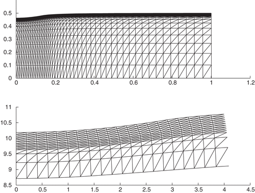
The deformed profile of the indented specimen and its scaled part under the indenter and near the contact zone, are shown in .
6. Parametrization of the inverse problem and least squares approach
First of all, note that in engineering practice an indentation curve cannot be measured continuously in the interval (0, αK). Therefore, one needs to assume the indentation data
, as a finite-dimensional vectors
,
in RK+1. The monotone increasing values 0<α0< α1<···<αK of the penetration depth generate the quasi-static indentation. For each αk, the maximal value of the strain intensity
for all finite elements will be denoted by ek. Such a parametrization naturally leads to the piecewise linear approximation
of the stress–strain curve (8). For the pure elastic and first plastic states, this approximation implies:
(37)
where β0 = 3G. For kth plastic state, the following approximation formula can be obtained:
(38)
where
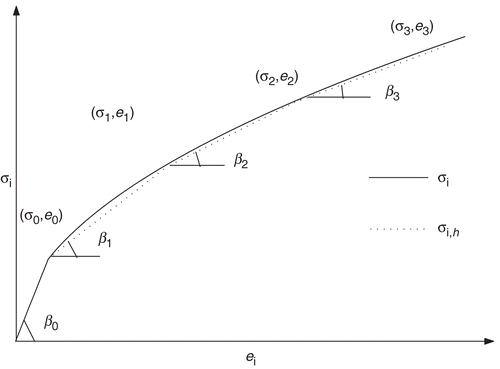
is defined as a state discretization parameter, and the angles βk – slope of the piecewise linear curve (38) (). The pairs ⟨αk, Pk⟩ on the plane OαP, correspond to the pairs ⟨ek, σk⟩ on the plane Oeiσi, where
. By this way, the inverse problem will be replaced by the problem of identifying the pairs ⟨ek, βk⟩ from the finite number of indentation measurements
. Due to the monotonicity of the stress–strain curve (8), the set of admissible unknown parameters will be defined as follows:
(39)
Thus the discrete inverse problem can be formulated as follows:
(40)
where the unknown parameters
and the measured data
are (K+1)-dimensional vectors. We assume that an appropriate numerical integration formula is applied to (12), and hence
is the finite-dimensional analogue of the nonlinear operator
, defined by (11–12).
Evidently a solution of the inverse problem in the sense of equation (40) may not exists, in general. We define a weak solution, according to a least squares approach: find , as a solution of the following minimization problem:
(41)
where
(42)
The parametrization scheme (38) shows that the functional (42) needs to be minimized for each
, which means the unknown parameters βk need to be determined on each kth state successively (step by step), by increasing the parameter ek. For ei<e0 only the elasticity modulus E > 0 needs to be found. For the first plastic state the algorithm of the inversion method consists of the following steps:
(i1) Choosing an initial iteration for the unknown parameter β1 > β0 and solving the forward problem for given data E, e0 and
.
(i2) Calculating the theoretical value of the loading force, corresponding to the iteration
.
(i3) Determining the next iteration by using the conditions: if
, then
; otherwise,
.
(i4) Determining the mth iteration by using the conditions: if
, then
.
(i5) Calculating the theoretical value of the loading force, corresponding to the iteration
.
(i6) Repeating steps (i4)-(i5) until the error .
The obtained value is assumed to be an approximate solution of the inverse problem (41), in the interval (e0, e1) of quasi-static indentation. The piecewise linear approximation
of the plasticity function g=g(ξ) in (e0, e1) can be obtained by substituting the found value β1 in equation (37):
.
In the above iteration process [steps (i3) and (i4)] the following fact taken into account: increasing the slope βk corresponds to an increase of rigidity of a material, and as a result, to an increase of the theoretical value of the loading force.
For the second plastic state of indentation the found parameters E, e0, and β1 will be used in (38) to determine the next parameter β2, by repeating the above algorithm. As an initial iteration here one needs to take .
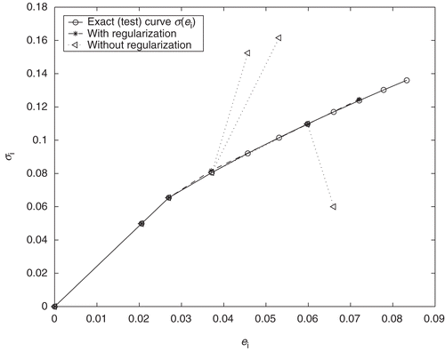
Two distinguished features of the discrete inverse problem need to be emphasized. First, solvability of the inverse problem is a result of monotonicity of the stress–strain curve, which for discrete model (41) means fulfillment of the monotonicity condition (39) for slopes βk, during the iteration process. Due to closeness of neighboring slopes for the developed plasticity states, and due to computational errors in βk, in practice, this condition may not be fulfilled. Second, all previously determined parameters ej, are included, as shows formulas (37–38), in the kth state. Subsequently, computational errors are compounded, and as a result, the second noise factor – computational noise factor arises. By increasing the number of states the influence of this factor will be increased. Hence for small values of state discretization parameters, the inverse problem may become unstable after some state k0. Illustration of this phenomenon is given by the piecewise linear curve
(), obtained by direct application of the above algorithm. The imitation of the quasi-static indentation process (for two pure elastic and eight plastic states) has been given here by the increasing values αk=αk−1+ Δαk of the penetration depth, where α0 =1.5×10⁻³ cm corresponds to the last pure elastic deformations. For the corresponding state discretization parameters ek, the following step sizes have been obtained:
. The measured data
for the considered inverse problem has been obtained from the quasireal experiment, for the power hardening material with κ = 0.5, e0=0.027, E = 210 GPa and R = 0.5 cm, by solving the forward problems (1–5), and then calculating the theoretical value of the loading force by (12). The numerical solution of the inverse problem for ϵP=10−6 shows that the iteration process diverges at the second plastic state k0 = 2 (the left broken line in ). The next increase of the state discretization parameter (
) again leads to divergence (the second broken line in ). For
inversion algorithm converges (the fourth point ☆ on the curve in ). The left broken lines also show that the corresponding slopes β3 do not satisfy the monotonicity condition (20). The similar behavior has been observed at the fifth plastic state. These results show that the inversion algorithm may not converge for arbitrary values of the state discretization parameters and within the strong fulfillment of condition (30).
In order to guarantee stability and convergence of the inversion method two regularization schemes – relaxation of the monotonicity condition for slopes βk, and optimization of the state discretization parameters Δek – have been added to proposed inversion algorithm. Introducing the relaxation parameter δβ>0 we will require that the unknown parameters βk satisfy the following relaxed monotonicity condition
(43)
Hence, we define the new set of admissible unknown parameters as follows:
then instead of
, defined by (39).
An optimal choice of the state discretization parameters has been realized as follows. Let us assume that the inversion algorithm converges at k − 1-th plastic state, but diverges at kth plastic state, i.e., neither condition (39) nor the condition
(44)
hold. In this case, the parameter Δek is eliminated from the consideration and taking the new state discretization parameter
instead of the parameter Δek, the iteration process is repeated anew from the k − 1-th state. This process is repeated until the fulfillment of conditions (43) and (44) and the found step
is assumed to be a new state discretization parameter for the kth state. This modification leads to the natural selection of the state discretization parameters, also allows us to minimize the number of indentation measurements. In the considered above example, the optimal values
of the state discretization parameters are obtained
,
and
. The relaxation parameter δβ in is assumed to be δβ=0.3.
Remark 1 Considering the elasticity modulus, E > 0 of the tested material can be determined directly from formula (14). To illustrate this, let us identify E > 0 for the given measured (synthetic) data , which was obtained from the numerical solution of the elastic contact problems (1–5), for given E=210 GPa. Substituting the numerical solution of the contact problems (1–5) with E = 1 in the right hand side of (14) yields: P0=0.804 ×10⁻³ GPa. By (14)
, and hence E(0) =209.850 GPa. The relative error ϵE=|(E−Eh)/E| is about 0.07%, which shows high accuracy of the algorithm of finding the elasticity modulus. ▪
Remark 2 Determination of the elasticity limit e0 has been performed by using the inequality , where E(0) is the already found elasticity limit, and E(1) the value of the elasticity limit corresponding to the value
of the indentation depth. By increasing the value
there arises such a value
, for which the above inequality does not hold. The corresponding value e0=maxΩhei(u), obtained from the numerical solution of problems (1–5), is assumed to be the elasticity limit. This algorithm shows two indentation data for pure elastic deformations is enough for determination of the elasticity limit e0.
7. Numerical verification of the inversion method for noise free and noisy data
In experiments, the indentation curve can only be given with some measurement error Citation17, Citation19, as the finite number of measured data
,
. Here
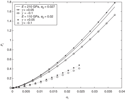
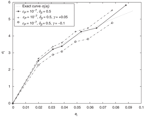
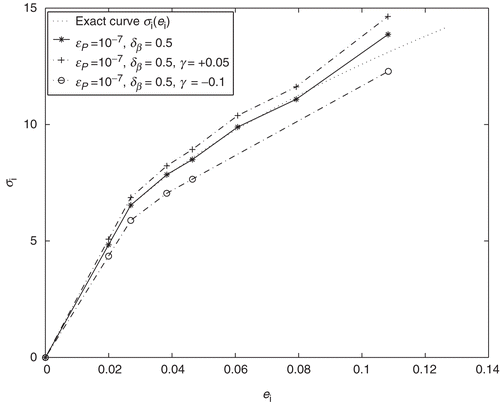
is an exact data corresponding to kth indentation step. In this case, in addition to the parameters ϵP>0 and δβ>0, the stability of the inversion algorithm with respect to the noise factor γ > 0 also arises. Two types of power hardening materials (with elasticity parameters E=110 GPa, e0=0.020 and E=210 GPa, e0=0.027) are selected to examine the proposed inversion method. The indentation curves for these materials, obtained by from the numerical solution of problems (1–5) with r0=0.5, κ = 0.5, are shown in . The noisy data
have been generated by taking γ = 0.05 and γ =−0.1. All these data have been then used as a synthetic data for identification of the curve
. The results are shown in and . For noise free data
, the reconstructions of the stress–strain curve have enough accuracy, in the both cases. Thus, the relative error
in the reconstructed curve, for the first material, is about ϵσ=3%, except the fifth plastic state (the last ☆-point in ). At this state the relative error was ϵσ=10%. This is due to the compounded errors in (38) from previous states, as was suggested above.
For the second type of power hardening material, the reconstruction of the stress–strain curves from noise free and noisy data, given in (bottom curves), are plotted in . In the case of the noisy data, an accuracy of the reconstructed curve for the first to fourth plastic states is about ϵσ=1%, and ϵσ=6%, for the fifth plastic state. For the noisy data accuracy of the reconstruction decreases, in particular in the beginning plastic states. For the noise factors γ =0.05;−0, 1 the relative errors rise up to ϵσ=12% and ϵσ=7%, for the first and second materials, respectively.
Note that, the noisy data also can change the optimal selection of the state discretization parameters, as shows the examples.
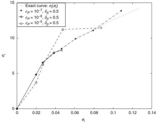
In the sense of accuracy and stability, here and in the previous example the similar behavior of the identified curves can be observed. This is due to the same stopping and relaxation parameters in the both cases: ϵP=10−7, δβ=0.5. The optimal value ϵP=10−7 of the stopping parameter in (44) was selected from series of computational experiments, taking into account the sensitivity of the solution of the nonlinear equation (11) (or (40)) with respect to the right hand side . An increase of the parameter ϵP>0 will naturally lead to the loss of accuracy. To analyze this situation, the identification problem was solved for the noise free data
obtained from the synthetic data given by upper solid line in . The identified stress–strain curves corresponding to the increasing values 10−7, 10−6, 10−5 of the parameter ϵP are shown in . Comparing the identified values σ2 (corresponding to the second plastic state) obtained for these three cases, one can clearly observe from that by increasing the stopping parameter an accuracy of the identified curves decreases.
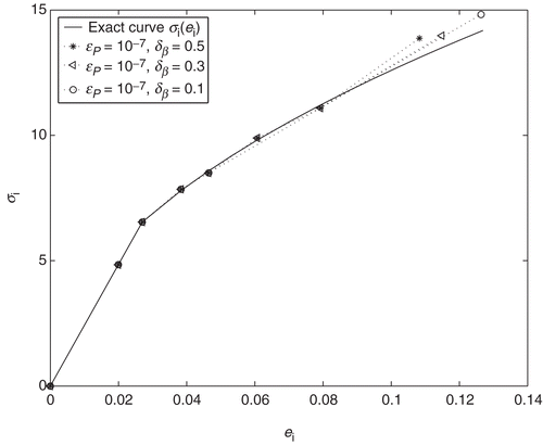
Let us analyze finally an influence of the relaxation parameter δβ used for stabilizaton of the above identification algorithm. For this aim, the above identification problem was solved for three various values ,
,
of the relaxation parameter. The results are shown in (Note that the identified curves –⋆–, corresponding to the parameter
, here and in , are the same). Thus, in the case of the large relaxation parameter
, the following optimal selection of state discretization parameters were obtained:
,
,
. In the case of small relaxation parameter
(curve −○− in ) only the first two state discretization parameters
remain the same:
and
. The third parameters
is essentially different from:
. The large optimal value
of the state discretization parameter is due to that the small relaxation parameter requires almost strict fulfillment of the monotonicity condition (39), and as a result, large steps
for the state discretization parameters ek, in order to guarantee the stability.
The obtained results show that the presented inversion algorithm is also feasible in the presence of a noise factor .
8. Conclusions
The inversion method for identifying the stress–strain curve from the measured indentation loading curve, during the quasi-static spherical indentation has been presented. An analysis of the ill-conditionedness of the considered inverse problem has been carried out theoretically, as well as computationally. The method is based on the FE discretization of the contact problem and parametrization of the stress–strain curve. The presented algorithm of optimal selection of state discretization parameters is a new and natural regularization algorithm for such a class of inverse diagnostic problems. The inversion method with this regularization algorithm permits one to not only determine effectively the stress–strain curve from the measured loading curve, but also suggests how one needs to simulate and select the limited number of experimental data , in order to minimize it. The demonstrated numerical results for different engineering materials show that the presented inversion method allows to determine the stress–strain curve σi=σ(ei) from the noise free, as well as noisy indentation loading curve, with high accuracy.
Finally, it should be emphasized that this study mainly focuses on the theoretical and computational aspects of the inversion method for considered here indentation problems. Further applications of the method, by taking into account such a physical and engineering aspects as geometrical nonlinearity, elastic deformations of the indenter, use of the unloading part of the indentation curve, will be especially useful and will be an essential part of the future research.
Acknowledgements
The author is grateful to Dr Z. Muradoglu for the assistance in providing the computational experiments. The author also gratefully thanks the referees for valuable suggestions which improved the revised version of the manuscript.
This work was partially supported by the Scientific and Technical Research Council of Turkey (TUBITAK).
References
- Ahn, JI, and Kwon, D, 2001. Derivation of plastic stress–strain relationship from ball indentation: examination of strain definition and Pilcup effect, Journal of Materials Research 16 (2001), pp. 3170–3178.
- Budiansky, B, 1959. A reassessment of deformation theories of plasticity, Journal of Applied Mathematics 26 (1959), pp. 259–264.
- Cao, YP, and Lu, J, 2004. A new method to extract the plastic properties of metal materials from an instrumented spherical indentation loading curve, Acta Materialia 52 (2004), pp. 4023–4032.
- Fleck, NA, and Hutchinson, JW, 2001. A reformulation of strain gradient plasticity, Journal of the Mechanics and Physics of Solids 49 (2001), pp. 2245–2271.
- Hasanov, A, 1995. An inverse problem for an elastoplastic medium, SIAM Journal on Applied Mathematics 55 (1995), pp. 1736–1752.
- Hasanov, A, 1998. Inverse coefficient problems for elliptic variational inequalities, Inverse Problems 14 (1998), pp. 1151–1169.
- Hasanov, A, and Seyidmamedov, Z, 1998. Determination of unknown elastoplastic properties in Signorini problem, International Journal of Non-Linear Mechanics 33 (1998), pp. 979–991.
- Hasanov, A, 2000. Qualitative behaviour of solutions of unilateral elliptic problems with perturbing the unknown boundary. I. The Theory, Applied Mathematics and Computation 109 (2000), pp. 249–260.
- Hasanov, A, 2004. Integral convexity argument for plasticticity function and monotonicity of iteration process for elastoplastic problems, International Journal of Non-Linear Mechanics 39 (2004), pp. 1217–1226.
- Ishlinski, AJ, 1944. Axisymmetric problem of plasticity and Brinell number, Prikladnaya Matematika I Mekhanika 8 (1944), pp. 204–224.
- Ivanov, VK, Vasin, VV, and Tanana, VP, 1978. Theory of Linear Ill-Posed Problems and Its Applications. Moscow: Nauka; 1978.
- Johnson, KL, 1970. The correlation of indentation experiments, Journal of the Mechanics and Physics of Solids 18 (1970), pp. 115–126.
- Johnson, KL, 1985. Contact Mechanics. Cambridge: Cambridge University Press; 1985.
- Kachanov, LM, 1974. Fundamentals of the Theory of Plasticity. Moscow: Mir; 1974.
- Kikuchi, N, and Oden, JT, 1988. Contact Problems in Elasticity: A Study of Variational Inequalities and Finite Element Methods. Philadelphia: SIAM; 1988.
- Kim, SH, Jean, E, and Kwon, D, 2005. Determining Brinell Hardness from analysis of indentation load-depth curve without optical measurement, Transactions of ASME 154 (2005), pp. 154–158.
- Kucharski, S, and Mroz, Z, 2001. Identification of plastic hardening parameters of metals from spherical indentation tests, Material Science and Engineering A318 (2001), pp. 65–76.
- Ma, D, Ong, CW, Lu, J, and He, J, 2003. Methodology for the evaluation of yield stress and hardening behaviour of metallic materials by indentation with spherical tip, Journal of Applied Physics 94 (1) (2003), pp. 288–294.
- Rikards, R, Flores, A, Ania, F, Kushnevski Balta, V, and Calleja, FJ, 1998. Numerical-experimental method for the identification of plastic properties of polymers from microhardness tests, Computational Material Science. 11 (1998), pp. 233–244.
- Swadener, JS, George, EP, and Pharr, GM, 2002. The correlation of the indentation size effect measured with indenters of various shapes, Journal of the Mechanics and Physics of Solids 50 (2002), pp. 681–694.
- Tabor, D, 1951. Hardness of Metals. Oxford: Clarendon Press; 1951.
- Tikhonov, A, and Arsenin, V, 1977. Solution of Ill-Posed Problems. New York: John Wiley; 1977.
- Wei, Y, and Hutchinson, JW, 2003. Hardness trends in micron scale indentation, Journal of the Mechanics and Physics of Solids 51 (2003), pp. 2037–2056.
