Abstract
Recently, a fully coupled formulation of the surface shape design problem, called the direct design approach, has been proposed in which both the target surface pressure and the unknown nodal coordinates appear explicitly in the formulations. The proposed method is generally applicable, but in the past it has only been applied in the context of ideal fluid flows [Ashrafizadeh, A., Raithby, G.D. and Stubley, G.D. 2003, Direct design of ducts. Journal of Fluids Engineering, Transaction ASME, 125, 158–165; Ashrafizadeh, A., Raithby, G.D. and Stubley, G.D. 2002, Direct design of shape. Numerical Heat Transfer-Part B, 41, 501–510; Ashrafizadeh, A., Raithby, G.D. and Stubley, G.D. 2004, Direct design of airfoil shape with a prescribed surface pressure. Numerical Heat Transfer, Part B: Fundamentals, 46(6), 505–527]. The present article extends the application of this method to the design of ducts carrying flows governed by the nonlinear coupled Euler equations, using a cell-centered finite volume method to discretize the governing equations. The details of the linearization and the imposition of the target pressure are discussed in this article. Also, the validation test cases and the design examples are presented, which show the robustness of the method in handling complex geometries and complex physical phenomena (such as shock waves). It is also shown that the computational cost of a direct shape design solution is comparable to the solution of the corresponding analysis problem.
1. Introduction
Surface Shape Design (SSD) in fluid flow problems usually involves finding a shape associated with a prescribed distribution of surface pressure or velocity. These design problems can be formulated and solved in a manner such that a number of flow analysis problems are solved a number of times in order to find the final desired shape. Here, this solution strategy is called the “iterative design approach”. The SSD problems can also be mathematically described by a fully coupled formulation in which all design and target variables are included. Once this formulation of the design problem is solved, the desired shape and the flow solution are obtained simultaneously. This strategy is called the “direct design approach”.
The iterative shape design approach relies on repeated shape modifications, such that each iteration consists of a flow solution followed by a geometry update. On the other hand, optimization methods Citation4, Citation5 are commonly used to automate the geometry modification in each iteration cycle. In such methods, an objective function (e.g., the difference between a current surface pressure and the target surface pressure) is minimized, subjected to the constraints that the flow equations be satisfied. Even though, the iterative methods are general and powerful, they are often excessively computationally costly and mathematically complex.
The traditional fully coupled approaches, on the other hand, transform the flow equations to a computational domain in which the unknown coordinates appear as dependent variables. Stanitz Citation6 solved two- and three-dimensional potential flow duct design problems using stream and potential functions as the independent variables.
Zanetti Citation7 also considered two-dimensional and axisymmetric Euler equations and mapped the physical domain to a fixed computational region. Scascighini Citation8 rewrote the Euler equations in a flow aligned system of coordinates using an inverse technique based on Keller's method Citation9. The three-dimensional extension of Scascighini's method was shown to be only valid for a flow field in which velocity and vorticity vector fields were perpendicular.
The existing fully coupled shape design formulations, based on coordinate transformation, are not generally applicable and are mathematically complex. However, their computational costs are comparable to the corresponding analysis problems.
A novel direct shape design method was proposed by Ashrafizadeh et al. Citation1–3. They basically showed that a fully coupled formulation of the SSD problem could be solved in the physical domain using a simple extension of commonly used CFD algorithms. Since the proposed direct design method does not need any transformation to or from a computational domain, it is applicable, in principle, to any flow model in two- and three-dimensional domains.
This article presents a direct (fully coupled) SSD method based on the ideas proposed by Ashrafizadeh et al. which has only been applied in the context of linear ideal fluid flows before Citation1–3. The nonlinear set of Euler equations are used here as the flow governing equations and a number of shape design problems are solved to validate the method and to provide shape design examples in subsonic and supersonic internal flows.
2. Overview
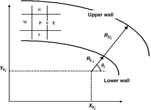
Consider a “flow analysis problem” in a duct with a given geometry as shown in . To numerically solve such problem, a computational grid is needed, which can easily be generated if the boundaries of the duct are described by an adequate number of nodes. The vector of flow unknowns, Q, can then be calculated if appropriate boundary conditions are used.
Now consider the corresponding “shape design problem,” in which, not only the flow unknowns, but also the boundary nodes are missing. Without the boundary nodes, the computational grid cannot be generated and in the absence of grid points, solution for the flow unknowns is impossible. Therefore, the constraint equations for the boundary nodal coordinates in SSD problems are needed to close the system of equations. The specified target pressure at the unknown boundary points provides one of the required constraints on the boundary nodal coordinates. An additional constraint on the location of a boundary point is still needed in a two-dimensional SSD problem. One way of obtaining the required constraint is to force the boundary node to move along a specified direction called the spine Citation1. By fixing the spine directions, only one constraint, the spine coordinate R, is needed to specify the location of a grid point in a two-dimensional domain. The spine coordinates of a node on the lower boundary (RLi) and a node on the upper boundary (RUi) are shown in .
Simple interpolation formulas can be used to relate any internal nodal coordinates to the corresponding boundary spine coordinates (RLi,RUi). Therefore, the computational grid in an SSD problem can be fully described by spine coordinates of boundary nodes. The relations between the Cartesian and the spine coordinates are as follows:
(1)
(2)
where, X0 and Y0 are the coordinates of the spine's origin ().
Due to the nonlinearity of the equations in the direct design approach, iterative solution is unavoidable. Therefore, an initially guessed shape is needed to start the nonlinear iterations. During every iteration, all boundary nodes are updated, i.e., they move along their spines. After updating the boundary nodes, all interior nodes are redistributed along their spines (with the same stretching factor).
3. Discretization and linearization of the Euler equations
The two-dimensional conservative form of the Euler equations is written as:
(3)
where,
(4)
In the above equations, ρ, u, v, e, and P denote density, velocity components, total specific energy, and pressure, respectively, and:
(5)
A fully implicit finite volume form of equation (3) for a quadrilateral cell is:
(6)
where, A is the cell area and the superscript “k” stands for the time level. The following linearization technique for the terms F and G in equation (5) is commonly used Citation10:
(7)
Since in inverse design problems the geometry changes during iterations, the robustness of the method (especially in the presence of shock waves) is crucial. First order upwind schemes are usually robust and have no oscillations in the presence of shock waves. Here, a simple form of such schemes is used to discretize the advection terms, in which a cell face value is approximated by its upstream nodal value Citation11. The face values of (∂F/∂Q)k and (∂G/∂Q)k are estimated using the average of two adjacent cell nodes.
4. Direct design method
As mentioned in section 2, the coordinates of the interior nodes are defined in terms of the boundary nodes. Then, the unknown coordinates of the boundary nodes are transformed into the spine coordinates (RL, and RU). The particular grid generation technique and the direct design method used are described, here.
4.1. Linear and orthogonal grid generation
The way internal nodes are related to the boundary nodes depends on the type of the grid used. We used one formulation to generate both linear and orthogonal algebraic grids. However, in our test cases no serious differences were observed using either ones. The coordinates of the grid nodes can be written as:
(8)
(9)
where, ξ and η are the body fitted coordinates along and perpendicular to the surface boundary, while XL and XU stand for the “X” coordinate of the nodes on the lower and upper boundaries, respectively. For a linear grid:
On the other hand, for an orthogonal grid, H1 and H2 are some third order polynomials, while Hx and Hy contain terms which enforce orthogonality at the wall boundaries Citation12. In the final system of equations, Hx and Hy appear in the right hand side and are taken from the previous iteration. Now, the final forms of the internal nodes’ coordinates in terms of the spine coordinates are as follows:
(10)
(11)
where, i and j designate the grid numbers in ξ and η directions, respectively.
4.2. Formulation of the direct design method
Since in direct design methods the unknown nodal coordinates appear explicitly in the formulations, there are several nonlinear terms due to the product of the geometrical and the physical unknowns. In this section, the required linearizations related to the internal cells are discussed. Linearizations associated with the boundary cells will be discussed next. The Newton linearization technique is applied as follows:
(12)
Substituting equations (6 and 11) into equation (5), one obtains:
(13)
Now, local time stepping and CFL numbers of about 1 and 0.5 for the analysis and design problems are respectively used.
The direct design method introduced here, not only works well but its convergence rate is the same order as the related analysis method. Where as, in many other iterative and fully coupled techniques, even for simple geometries, the inverse design methods need much more CPU time than their related analysis problems. This is discussed in more details in section 7.
The inverse design method used here starts with an initial guess, such that the duct's main characteristics (e.g., length and inlet or outlet area) are known. Recall, in incompressible flows, the inlet and outlet areas must be given, while in compressible flows, only one of them needs to be specified.
4.3. Implementation of the target pressure
To impose the target pressure at a boundary node, there is a pure thermodynamic relation, equation (4), which is independent of the geometries variables (unknowns). Therefore, this form of the equation is not suitable for the extra boundary condition of the direct design method. After several investigations, the continuity equation which contains both physical and geometrical unknowns was used as:
(14)
Using equation (4), ρk+1 is obtained as:
(15)
Now, inserting equation (14) into equation (13), the following new form of the continuity equation is obtained:
(16)
As seen, the given pressure is enforced into the continuity condition. A delicate linearization of equation (15) is necessary to achieve convergence in our iterative algorithm. If lagging linearization technique is used for the second term in the left hand side of equation (15), the inverse design method will be stable, but the evolution from the initial guess to the final shape does not occur (the initial guess remains unchanged). The reason is the weak coupling between the physical and the geometrical variables in this linearization technique. The other option is using the Newton linearization technique, which yields instability and thus divergence of the method. However, according to our experiences, such linearization is necessary because of the strong coupling between the physical and the geometrical variables. To have a stable Newton linearization technique, an under relaxation was first used for the geometrical terms in equation (15), which did not work. But, applying under relaxation for the physical terms (about 0.1 to 0.2) worked well with relatively fast convergence. Thus,
(17)
where, ω stands for under relaxation factor. Now, using equation (6), the final form of equation (15), as our extra boundary condition, can be written as:
(18)
Since ΔQk goes to zero during the iterations, the corresponding term in the right hand side was neglected in the above equation. Note, “Area” is preferably written in terms of the geometric unknowns, which increases the convergence rate considerably. Ak+1 for a cell (i, j) is obtained as follows:
(19)
There are several ways to linearize the “Area”, where the above form was shown to be more suitable.
5. Validation cases
In all validation and design cases studied, computations were performed using a Pentium IV PC computer with 2.8 GHz CPU and 512 MB RAM. The iterations were stopped after the residuals were reduced four orders of magnitude (). Residual was defined as , which was normalized using the residual related to the first iteration. The pressure and density were normalized by their values at the duct inlets and all duct lengths were nondimensionalized by their inlet heights in this article. Other quantities were also normalized accordingly. Note that since the computed and the target pressure distributions along the solid walls are extremely close, only the target ones are plotted in the related figures.
Table 1. Grid, iteration number, and CPU time for test cases studied here
5.1. Channel with a bump
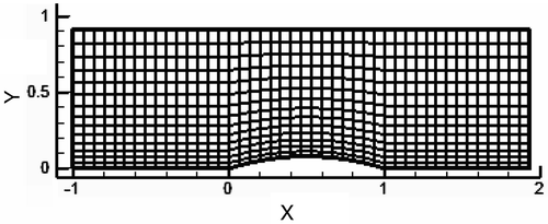
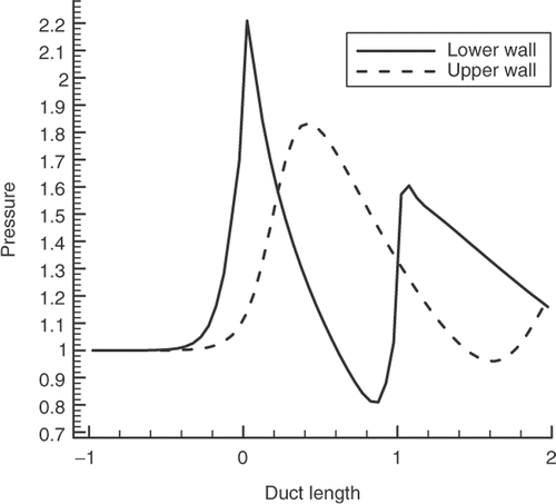
A two-dimensional straight channel () with inlet Mach number of 1.4 containing a bump at its lower wall was considered first. The target pressure distribution for this configuration is uniform along the upper and lower walls (corresponding to rectangular channel with no bump). Using a 45 × 15 grid, the final channel geometry was obtained after 842 iterations. The reverse of this problem (a rectangular channel as the initial guess and using the bumped wall pressure () as the target) was also investigated, for which the number of iterations was 1450 (Only the latter case is reported in ).
5.2. Wind tunnel supersonic nozzle
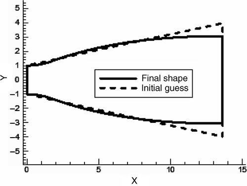
A supersonic wind tunnel nozzle was considered next. Using the method of characteristics Citation13, the nozzle geometry was first designed for inlet and outlet Mach numbers of 1.05 and 2.57, respectively. The wall pressure distribution for this supersonic nozzle was used as the target for a shape design problem. The initial guesses for the upper and lower walls were simple flat plates. Figures and show the related target wall pressure distribution and the nozzle geometry.
5.3. Nozzle with normal shock
The target pressure distribution for the third validation test case was obtained from the solution of the flow through the following nozzle:
Entrance area = 2, Exit area = 2.86, Length = 4.6, Entrance Mach number = 1.05, Entrance pressure = 1, Back pressure = 1.5.
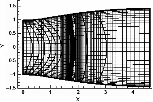
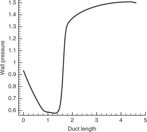
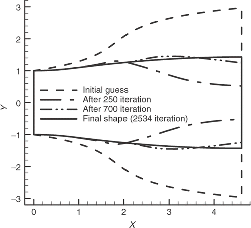
The 70 × 30 grid and the nozzle pressure contours are shown in . The calculated pressure distribution along the walls is shown in , while illustrates the initial guess and the evolution of the shape after 250, 700, and 2534 iterations. As shown in , since the initial guess is not a suitable one, severe shape changes occur during its evolution. Although inverse design with normal shock waves may have less application, it well presents the great capability of our design method. Several cases with oblique shocks (not presented here) were also tested, which worked as well.
6. Design cases
Two different design cases (ideal nozzles and ideal S-shaped ducts) are presented here. The inlet area and the length of nozzles were specified and grid refinement studies were performed for both the analysis and the design problems ().
6.1. Design of an ideal nozzle
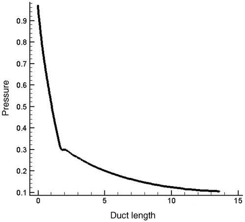
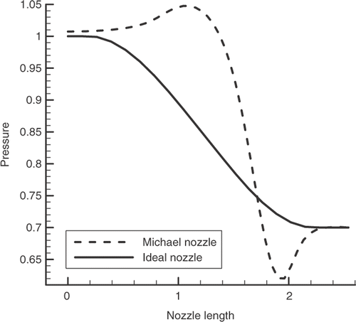
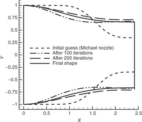
In a subsonic nozzle, in which the flow speed gradually increases in the streamwise direction, favorable pressure gradients exist along most parts of the walls. As shown in , pressure increases in two small regions, in which a viscous flow might separate from the walls. The goal of this example is to design an ideal nozzle in which there is no undershoot and/or overshoot in its wall pressure profile. For such smooth wall pressure distribution (, solid line), the flow remains subsonic and separation will not occur in real flows. shows a nozzle design case in which a monotonic target pressure drives the initial guess (a Michael nozzle with inlet area of 2) towards the final desired shape.
6.2. Design of S-shaped ducts
Using the direct design method developed in this work, one can find the appropriate geometry for S-shaped ducts which are used as the diffusers in the intake section of jet engines. Because of considerable adverse pressure gradients along their walls, the possibility of flow separation is very high in such ducts. Besides, small regions may exist near the inlet where the velocity increases up to supersonic regime. Although adverse pressure gradients are not avoidable in such ducts, one looks for S-shaped ducts without overshoot and/or undershoot in their wall pressure profiles, in order to have no shock waves and to reduce flow separation possibilities.
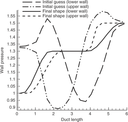
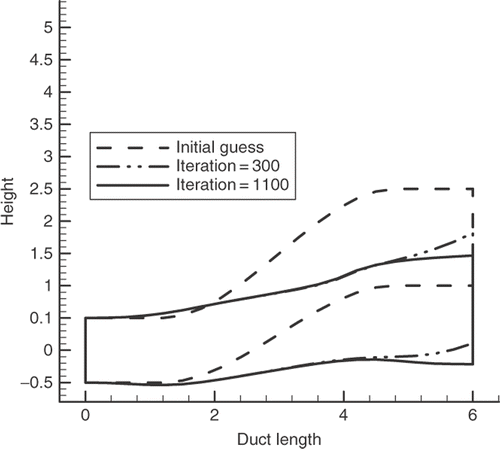
Here, we consider an S-shaped duct with inlet area and length of one and six, respectively. The wall Mach number distribution of the initial guess and the target distribution are illustrated in . Note that in the vicinity of the inlet, the Mach number becomes greater than unity and thus the flow becomes supersonic in the initial shape. This difficulty is completely removed in the final shape duct (). As noted earlier, in compressible flows the area and the vertical location of the exit section depend on the target wall pressure distribution and can not be specified in advance.
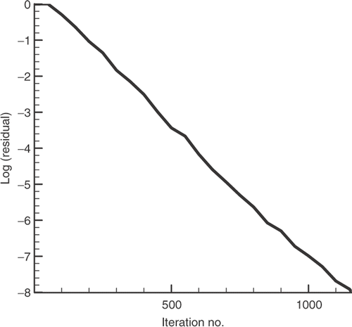
Finally, the variation of the related residual for this case with a 20 × 8 grid is shown in .
7. Results and discussion
Since in the direct design method there are several nonlinear terms due to the product of the geometrical and the physical unknowns, the nonlinearity of the governing equations is more than that of the analysis problem. Therefore, the convergence behaviors of the two problems are not necessarily the same. In most cases examined here, the design method converged quickly and almost monotonically up to 12–14 orders of residual reduction. The only exception was the ideal nozzle (section 5.1) wherein the convergence was slow and oscillatory.
As far as the stability of our design method is concerned, no serious difficulties were noted, except in the presence of strong normal shock waves. For example, the design method diverged for supersonic nozzle mentioned in section 5.2, when normal shock wave was to be appeared. Thus, another nozzle with lower area ratio (1.43 instead of 3) was chosen as the related target duct shape (section 5.3).
The last note is about the required CPU time. Three grids (20 × 8, 45 × 15, and 60 × 20) were considered for this investigation. As shown in , the required iteration number for the analysis problem is more than that of the related design problem. However, the required CPU time for both methods is roughly the same. This is due to the use of appropriate initial values in the direct design method. To provide reasonable initial values (and thus faster convergence), the required initial nodal values are obtained using interpolation of the boundary values (given pressure along the solid walls).
As far as the extension of this method to external flows is concerned, the direct design of airfoils in the context of the Euler flow model is currently under investigation by our research team. It is expected that the methodology suggested in Citation3 can be employed to solve the Euler flow airfoil design problems as well.
Another point is that the direct design approach developed in this work has not yet been extended to three-dimensional and/or viscous flows. However, since it uses regular forms of the governing equations and also no transformation is used from physical to computational domain, we believe it is extendable to three-dimensional and/or viscous flows. Note that the method used ideal flow assumption initially, but was developed here for inviscid compressible flows.
8. Conclusions
In this work, we developed a fully coupled internal flow direct design technique in which the boundary nodal coordinates appeared as dependent variables. The Euler equations using a cell-centered finite volume method and a robust first order upwind scheme were used. Our design cases included an ideal straight nozzle and an S-shaped diffuser. The direct design approach proved to be suitable for the above cases with high convergence rates even in the presence of oblique or weak normal shock waves. The required CPU time was the same order as the analysis problem.
References
- Ashrafizadeh, A, Raithby, GD, and Stubley, GD, 2003. Direct design of ducts, Journal of Fluids Engineering, Transaction ASME 125 (2003), pp. 158–165.
- Ashrafizadeh, A, Raithby, GD, and Stubley, GD, 2002. Direct design of shape, Numerical Heat Transfer-Part B 41 (2002), pp. 501–510.
- Ashrafizadeh, A, Raithby, GD, and Stubley, GD, 2004. Direct design of airfoil shape with a prescribed surface pressure, Numerical Heat Transfer, Part B: Fundamentals 46 (6) (2004), pp. 505–527.
- Cheng, C-H, and Wu, C-Y, 2000. An approach combining body fitted grid generation and conjugate gradient methods for shape design in heat conduction problems, Numerical Heat Transfer, Part B 37 (1) (2000), pp. 69–83.
- Jameson, A, 1994. Optimal design via boundary control, In AGARD-VKI Lecture Series, Optimal Design Methods for Aerodynamics (1994), pp. 3.1–3.33, Von Karman Institute for Fluid Dynamics.
- Stanitz, JD, 1987. A review of certain inverse methods for the design of ducts with 2- or 3-dimensional potential flows. Presented at Proceedings of the Second International Conference on Inverse Design Concepts and Optimization in Engineering Sciences (ICIDES-II).
- Zanetti, L, 1986. A natural formulation for the solution of two-dimensional or axis–symmetric inverse problems, International Journal for Numerical Methods in Engineering 22 (1986), pp. 451–463.
- Scascighini, A, 2001. "A numerical method for the design of internal flow configurations based on the inverse Euler equations". In: PhD Thesis. Zurich: Swiss Federal Institute of Technology; 2001.
- Keller, JJ, 1998. Inverse Euler equations, Zeitschrift fur Angewandte Mathematik und Physik 49 (3) (1998), pp. 363–383.
- Beam, RM, and Warming, RF, 1976. An implicit finite-difference algorithm for hyperbolic systems in conservation law form, Journal of Computational Physics 22 (1) (1976), pp. 87–109.
- Ferziger, JH, and Peric, M, 1999. Computational Methods for Fluid Dynamics. Berlin: Springer-Verlag; 1999.
- Kowalski, EJ, 1980. Boundary fitted coordinate systems for arbitrary computational regions, Numerical Grid Generation Techniques, NASA, Conference Publications 2166 (1980), pp. 331–353.
- Anderson, JD, 2005. Modern Compressible Flow. New York: McGraw-Hill; 2005.
