Abstract
The goal of this article is to provide a simple and fast numerical method to estimate an internal shape of a material by exploiting certain measurements performed on its external boundary. This inverse problem is formulated as a least-squares minimization problem. A numerical approach to this minimization problem based on the domain derivation ideas is outlined. Real implementation is achieved with the Freefem software. Numerical tests are provided to demonstrate the efficiency of the proposed method. Special attention is given to the impact of the material thermophysical properties on the quality of the identification. The effect of the errors in the measurements on the identification is also investigated.
1. Introduction
Techniques of inverse problems have been, widely, applied in estimating parameters of thermal processes such thermal conductivity, specific heat capacity, boundaries conditions Citation1–4. These techniques have also been used in estimating some inaccessible part of the boundary of a domain being moving Citation5–7 or fix Citation8–10. Thermal imaging, which is a technique based on these inverse methods, is employed in detecting eventual defects or cracks within a manufactured material. It consists in applying a known heat flux on the accessible boundary and measuring the temperature response. Then, by inverse resolution, identify internal shape or parameters. Several studies devoted to problems of shape identification using steady heat equation, have been reported in literature Citation8,Citation9,Citation11–13. Also other inverse geometric problems using steady thermographic techniques, known as infrared computerized axial tomography IR-CAT, have been considered in Citation14–16.
The mathematical development of the domain-derivative techniques allows the construction of efficient numerical algorithm able to recover the shape of a domain from some measurements, performed on accessible boundaries Citation17–19. The unsteady heat equation is considered in these works. In this context, we propose to identify an internal boundary of a material from the knowledge of the heat flux and the temperature on the external one. We assume that the internal boundary is in contact with a medium at uniform temperature. This boundary is kept under a constant temperature condition.
The outline of this article is as follows. In section 2, we first begin by setting the equations governing the heat transfer in the material and then we set the physical problem. In section 3, we parameterize the unknown boundary by approximating its radial function using trigonometric polynomials and terminate by formulating the corresponding mathematical optimization problem. The derivation of the temperature with respect to the boundary is obtained through the solution of an initial boundary-value problem presented in section 4. Section 5 is devoted to space and time discretizations, numerical algorithm and the used FreeFem subroutines. In the last section, we present a variety of numerical tests of the proposed method carried out with simulated measurements.
2. Posing of the physical problem
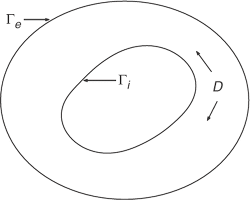
The considered material occupies the bounded domain D ⊂ ℝ2 with smooth boundary Γ = Γi ∪ Γe, as shown in .
The temperature evolution in the material is described by the following system:
(1)
where ρ, c and λ are the density, the specific heat capacity and the thermal conductivity of the material, respectively. These parameters are assumed to be constant, which is justifiable if temperature variations are sufficiently small. Q represents the energy, per unit volume and per time, generated or released. The vector n is the outward unit normal on Γ.
The physical problem, we are concerned with, is to determine the internal boundary Γi from the temperature measurements φ performed on the external boundary Γe at specified points xi (i = 1 to Nx) and discrete times tj (j = 1 to Nt). We assume that there is a single cavity in the material and that its boundary Γi is assumed to be a simple closed curve. The input heat flux ϕe, the quantity Q and the constant Ti are well-known.
Such problems have been mathematically examined in Citation17,Citation18 for the case Q = 0 and continuous flux and temperature measurements. The authors in Citation17,Citation18 have used an identification approach based on the boundary element method. Moreover, an identification approach based on a finite element method, which is able to handle more general heat equation, has been proposed in Citation20.
In the present article, we consider:
| • | Q ≠ 0 to take into account a non-negligible energy exchange with the exterior. Q can also represent a heat source, specially, introduced to improve the estimation quality; | ||||
| • | discrete temperature measurements that is more realistic in practice, further, measuring a temperature is more easy and precise than measuring a flux; | ||||
| • | physical values of thermal properties to point out their influence on the identification quality which cannot be seen if only dimensionless equations are being considered. | ||||
3. Formulation of the approximate inverse problem
A numerical implementation requires a parametrization of the unknown boundary. We assume that Γi is starlike with respect to the origin. Therefore, it can be described by the following parametric representation:
where r is the radial function satisfying r(0) = r(2π).
For numerical resolution, this radial function is approximated by trigonometric polynomials of degree less than or equal to K, i.e.
where
Setting
and rex the radial function of the boundary Γe, then we define the set of admissible vectors
by
The problem of identification of Γi can now be set as: find
in such a way that the calculated temperature by system (1) is close to the measurements φ(xi, tj).
Let A be the operator which associates to the vector , the function defined on Γe×[0, tf] by:
, where T is the solution of system (1) with the corresponding boundary
.
In the classic way, the above identification problem is often formulated as a minimization of the following output least-squares criterion
The term in β is introduced to deal with the ill-posedness of this inverse problem (second-order regularization) Citation22.
However, the operator is a function strongly non-linear, direct minimization of R can fail. Therefore, we opt for the iterative Newton method, mostly used in the domain of shape estimation Citation17–19,Citation23. This method consists in linearizing
and instead of minimizing
, the following criterion
(2)
is minimized with respect to a new variable
. Once
is determined,
is updated by
and the new criterion
is optimized. The process is repeated until convergence. The full algorithm will be presented in section 5.
In the next section, we will establish , the gradient of A which involves a domain derivation.
4. Gradient establishment
By definition
where
is the k-th element of the ℝ2K+1 canonical base.
Let be the boundary corresponding to the vector
. Its radial function is
.
Then, , which is, in the domain derivative terms, a perturbation of the boundary
in the direction a = qk(θ)(cos θ, sin θ).
Strong calculations similar to those carried out in Citation17 lead to the following result:
Let v be the solution of the system
(3)
then
(4)
where a = qk(θ)(cos θ, sin θ).
5. Numerical implementation
The systems of partial differential equations (1) and (3) are discretized by means of an implicit scheme in time with a step δt. The resulting equations are solved by the finite elements software FreeFem + + Citation21. Linear piecewise P1 or quadratic P2 functions are used. The domain D meshing is generated by dividing the boundaries Γi and Γe by integer numbers. The same number, N, is chosen in our case.
The minimization of is achieved by the FreeFem subroutine linearCG Citation21. This subroutine minimizes
by computing the roots of the equation
, using a conjugate gradient method. It requires an initialization of vector
, a real ξ to stop the process when
, and the expression of
which is given by
(5)
Finally, the identification algorithm can be summarized as follows:
| 1. | start with initial known vector | ||||
| 2. | solve the direct system (1) with parameters δt and N. This makes | ||||
| 3. | for each k (varying from 0 to 2K), set a = qk(θ)(cos θ, sin θ) and solve the system (3). This gives the gradient | ||||
| 4. | minimize (2), starting from a vector | ||||
| 5. | make | ||||
As a stopping test, we take where
.
6. Numerical tests
6.1. Measurements simulation
The measurements φ are simulated by numerically solving the direct system (1) with Γi characterized by a radial function r*. Two boundaries, denoted by C1 and C2, and described respectively by
are considered here.
We choose as material silver with its thermal properties ρc = 2.467(106 Jm−3°C−1 and λ = 420 (W m−1 · C−1).
The external boundary is the circle of radius R = 0.15(m) and centered at the origin. The boundaries conditions are Ti = 25 (°C) and ϕe(x, t) = 25(1 − exp(−t/100)) (kW m−2). We take the values of Q and time measurements tf as 250t(W m−3) and 200(s), respectively.
The discretization parameters are δt = 10(s), N = 50 and P2 finite elements.
Once the temperature distribution T is available, the measurements φ are simulated by adding random errors as follows: φ(xi, tj) = T(xi, tj) + μσT(xi, tj) where μ is a random number in the interval [−1, 1], σ represents the magnitude of the errors, tj = 10j (j = 1 to 20) and xi = R(cos(θi), sin(θi)), , (i = 1 to 20).
6.2. Identification results
We try now to reconstitute the exact boundaries by the proposed inverse method. For this, systems (1) and (3) are solved with δt = 10 (s), N = 50 and P1 finite elements. We take 6 for the number of allowed iterations, K = 4 as a degree of the trigonometric polynomials approximation and 0.005 for the stopping test δ. The algorithm is initialized by the circle centered at the origin with radius of 0.1 (m). The subroutine LinearCG is initialized by with a stop test ξ = 0.0001.
As the function to be minimized, Jm(p), varies at each iteration m, the regularizing parameter αm is also adapted. We choose, by trial and error, .
To quantify the identification quality, we define the relative error between the exact curve and the estimated one by: E = (|r − r*|/|r*|), where r is the radial function obtained by the inverse resolution.
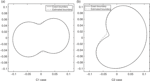
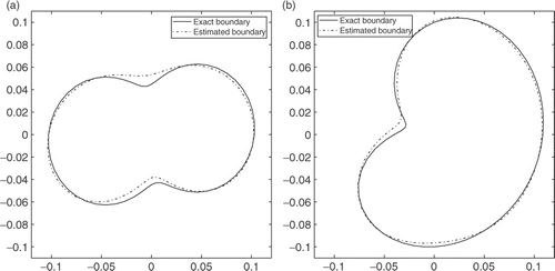
By considering, first, exact measurements (σ = 0), the identification algorithm converges after three iterations (m = 3). The obtained relative error is E1 = 0.0138 for the curve C1 whereas for C2 this error is E2 = 0.0352. depicts the estimated boundary and the exact one for C1 and C2 cases. The match between the exact boundaries and the estimated ones is good with relative errors less than 4%.
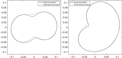
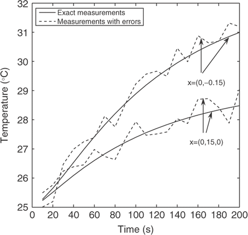
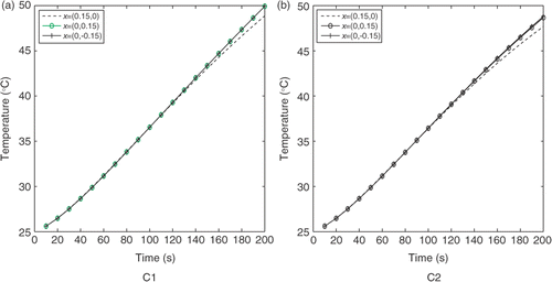
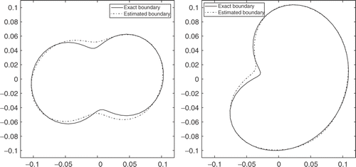
Now, considering, measurements with errors of 2%(σ = 0.02) plots the evolution versus time of the simulated measurements (exact and with errors) at points x = (0.15, 0) and x = (0, −0.15), obtained with C1 curve. The identification algorithm always converges after 3 Newton steps. However the relative error E1 increases significantly to 0.0531 while E2 increases slightly to 0.0370. On the other hand, shows that the identification, using measurements with errors of 2%, is also reasonably good.
If the errors in the measurements increase to 5%, the identification of C1 becomes difficult (E1 = 0.1435) and that of C2 is still possible and good (E2 = 0.0492). The sensitivity of C1 identification to the level of errors in the measurements is related to the distance between C1 points and the boundary where the measurements are performed, which is higher in the case of C1 compared to C2. To illustrate that, we multiply the radial function of C1 by a factor 1.2, the identification becomes possible and the relative error decreases considerably to reach 0.067.
6.3. Influence of material properties
The purpose of this section is to point out the influence of the thermal properties of the material on the identification. For this end, we consider materials: gold, silver, copper and steel, whose thermophysical properties are given in . Noting that Ds = λ/ρc is the thermal diffusivity of the material.
Table 1. Materials properties
The previous identification process is repeated for each material and the obtained results are reported in .
Table 2. The obtained relative errors–measurements with errors 2%
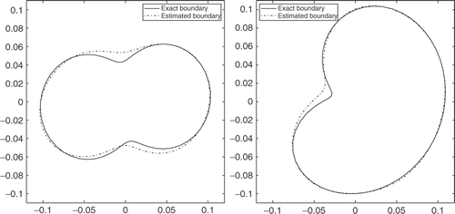
According to , it can be concluded that for silver, gold and copper with high and comparable thermal diffusivity, the quality of the identification is practically the same. Noting also that the identification of C2 is more accurate than that of C1. indicates a good agreement between the estimated boundaries and the exact ones for copper case. Furthermore, for all these materials, the temperature varies between initial value 25 (°C) and a maximum of 32.5 (°C), which implies that the adopted linear model for the heat equation holds well.
For steel, the quality of identification is bad for the considered horizon tf and the applied heat flux. In fact, the effect of the inner boundary on the external temperature measurements necessitates time to appear, due to the low-thermal diffusivity of the material. In order to illustrate this, we plot on the evolution, versus time, of the simulated temperatures at some specified points on the external boundary. As can be seen, the temperatures on all these points are the same over a wide interval of time ([0,120 (s)]), independently of C1 and C2. Beyond 120 (s) the sensitivity of the external temperature to the shape of the inner boundary becomes pronounced and maximal near 200(s), where the temperatures obtained with C1 and C2 are significantly different. However, in the case of silver, the effect of the inner boundary on the external temperatures begins to appear from 10(s) as shown in . When the measurements (with errors of 2%) are kept for longer time (tf = 400 (s)), the proposed method, as shown in , leads to an accurate estimation of the unknown boundaries (E1 = 0.0534 and E2 = 0.0371). Moreover, the temperature measurements vary from 25 (°C) to 68 (°C) over [0,400 (s)]. If the linearity of the adopted thermal model risk to be compromised by this temperatures range, we can seek for an input heat flux which reduce this range. By taking for example, ϕe,2(x, t) = 25(exp(−t/50)(kW m−2), the considered curves can be identified with good accuracy as shown in (E1 = 0.0552 and E2 = 0.0425), with a measurements range [25 (°C), 32.6 (°C)].
7. Conclusion and perspective
In this work, we have presented an identification problem of an internal boundary of a material from discrete temperature measurements performed only on the external boundary. We have set and formulated this problem as an optimization problem. We have then presented and implemented an algorithm to solve this optimization problem. This gradient-based algorithm used the domain derivative techniques and finite elements method. The numerical tests carried out show that the proposed method is able to estimate the internal boundary from temperature measurements with errors less than 2%. The quality of the identification decreases when the distance between the inner boundary and the points where the measurements are performed increases. In addition, the horizon time is to be kept in connection with the thermal diffusivity of the considered material. Seeking for optimal input heat flux which maximizes the measurements sensitivity to the shape of the inner boundary, for a given material and a given horizon time, is an interesting task. The case where the boundary to be identified is under a heat flux condition is also of interest and will continue from this work.
References
- Moultanovsky, A, and Rekada, M, 2002. Inverse heat conduction problem approach to identify the thermal characteristics of super-hard synthetic materials, Inverse Problems in Engineering 10 (2002), pp. 19–33.
- Hsu, PT, Yang, YT, and Chen, CK, 1998. Simultaneously estimating the initial and boundary conditions in a two-dimensional hollow-cylinder, International Journal of Heat and Mass Transfer 41 (1) (1998), pp. 219–227.
- Tervola, P, 1989. A method to determine the thermal conductivity from measured temperature profiles, International Journal of Heat and Mass Transfer 32 (1989), pp. 1425–1430.
- Hao, DN, and Reinhardt, HJ, 1998. Gradient methods for inverse heat conduction problems, Inverse Problems in Engineering 6 (1998), pp. 177–211.
- Chaji, K, and El Bagdouri, M, 2005. Numerical resolution of an inverse 2D Stefan probelem. In 5th International Conference on Inverse Problems in Engineering. UK: Cambridge; 2005.
- Liu, J, and Guerrier, B, 1997. A comparative study of domain of embedding methods for regularized solutions of inverse Stefan problems, International Journal of Numerical Methods and Engineering 40 (1997), pp. 3579–3600.
- El Bagdouri, A, and Moutazaim, F, 1999. A one phase inverse Stefan problem, Inverse Problems 15 (1999), pp. 1507–1522.
- Hang, CH, and Shih, CH, 2006. A shape identification problem in estimating simultaeously two inerfacial configurations in multiple region domain, Applied Thermal Engineering 26 (2006), pp. 77–88.
- Su, CR, and Chen, CK, 2007. Geometry estimation of the furnace inner wall by an inverse approach, International Journal of Heat and Mass Transfer 50 (19–20) (2007), pp. 3767–3773.
- Bryan, K, and Caudill, LF, 1998. Stability and reconstruction for an inverse heat equation, Inverse Problems 14 (1998), pp. 1429–1453.
- Bryan, K, and Caudill, LF, 1996. An inverse problem in thermal imaging, SIAM Journal of Applied Mathematics 56 (1996), pp. 715–735.
- Hang, CH, and Chao, BH, 1997. An inverse geometry problem in identifying irregular boundary configurations, International Journal of Heat and Mass Transfer 40 (1997), pp. 2045–2053.
- Cheng, CH, and Chang, MH, 2003. Shape identification by inverse heat transfer method, Journal of Heat and Transfer 125 (2003), pp. 224–231.
- Kassab, AJ, and Pollard, JE, 1993. Automated algorithm for nondestructive detection of subsurface cavities by the IR-CAT method, Journal of Nondestructive Evaluation 12 (3) (1993), pp. 175–186.
- Kassab, AJ, and Pollard, JE, 1994. Cubic spline anchored grid pattern algorithm for high-resolution detection of subsurface cavities by the IR-CAT method, Numerical Heat Transfer Part B 26 (1994), pp. 63–77.
- Divo, E, Kassab, AJ, and Rodriguez, F, 2004. An efficient singular superposition technique for cavity detection and shape optimization, Numerical Heat Transfer Part B 46 (2004), pp. 1–30.
- Chapko, R, Kress, R, and Yoon, J, 1998. On the numerical solution of an inverse boundary value problem for the heat equation, Inverse Problems 14 (1998), pp. 853–867.
- Chapko, R, Kress, R, and Yoon, J, 1999. An inverse boundary value problem for the heat equation: the Neuman condition, Inverse Problems 15 (1999), pp. 1033–1046.
- Chapko, R, and Kugler, P, 2004. A comparison of the Landweber method and the Gauss-Newton method for an inverse parabolic boundary value problem, Journal of Computational and Applied Mathematics 169 (2004), pp. 183–196.
- Chaji, K, and El Bagdouri, M, 2007. A shape domain estimation for the heat equation, International Journal of Ecological Economics Statistics 9 (F07) (2007), pp. 47–56.
- Hecht, F, et al., FreeFem++ manual, Available at http://www.freefem.org.
- Alifanov, O, Artykhin, E, and Rumyantsev, S, 1995. Extreme Methods for Solving Ill-posed Problems with Applications to Inverse Problems. New York: Begell House; 1995.
- Hettlich, F, and Rundell, W, 1996. Iterative methods for the reconstruction of an inverse potential problem, Inverse Problems 12 (1996), pp. 251–266.
