Abstract
A simultaneous estimation of two boundary conditions in a two-dimensional linear heat conduction problem is proposed by numerical approach. The aim is to estimate the evolution of the distributions of the unknown surface heat fluxes from the transient temperature histories taken with several sensors inside a two-dimensional specimen. The inverse numerical algorithm is based on the iterative regularization method and on the conjugate gradient method. Unknown functions are parametrized in the form of a cubic B-spline. The utilization of an optimal choice of the matrix of the descent parameters is at the origin of this method showing an increase in the convergence rate. The effects of the parameters of the cubic B-spline approximation, the number and the position of the sensors and the magnitude of measurement errors on the inverse solutions are discussed.
Nomenclature
| a, b | = | dimensions of the specimen, m |
| bx | = | random noise |
| C | = | specific heat, J kg−1 °C−1 |
| fn | = | measured temperature at position (Xn, Yn), °C |
| hi | = | heat transfer coefficient, W m−2 °C−1 |
| My, Mt | = | numbers of approximation parameters |
| N | = | number of temperature sensors |
| Nt | = | number of time steps |
| Nx, Ny | = | number of nodes in the x, y directions |
| qi(y, t) | = | heat flux density, W m−2 |
| T | = | temperature, °C |
| Ta, T0 | = | ambient, initial temperature, °C |
| t, tf | = | time, final time, s |
| ψ | = | adjoint variable |
| ϑ | = | temperature variation, °C |
| ρ | = | density, kg m−3 |
| λ | = | thermal conductivity, W m−1 °C−1 |
| α | = | thermal diffusivity, m2 s−1 |
| δ2 | = | estimated error or criterion |
| Δt | = | time step; s |
| Δx, Δy | = | spatial grid in the x, y directions, m |
| ΔFo | = | delta Fourier number |
1. Introduction
Most heat transfer processes occurring in industrial applications require accurate knowledge of the thermal properties of the material and surface conditions. Practically, measurements are often made of temperature and displacement, etc. Thereafter, physical quantities and surface conditions may to be estimated from these measurements. Such problems are called inverse problems and recently have become an interesting subject. To date, various methods have been developed for the analysis of the inverse heat conduction problems involving the estimation of the surface conditions from measured temperatures inside the material. Most of the analytical and numerical methods only deal with one- two- or three-dimensional inverse heat conduction problems (IHCP) to estimate a single surface condition Citation1–7. However, a few works estimate more than one surface condition in two- and three-dimensional problems.
Chen et al. Citation8 have applied the Laplace transform technique and finite-difference method with a sequential in time concept. The least square scheme is proposed to predict the unknown surface temperature of two-sided boundary conditions for a two-dimensional inverse heat conduction problem.
Hsu et al. Citation9 have used the finite difference method in conjunction with the linear least squares method to estimate the one-sided and two-sided boundary conditions in two-dimensional IHCP. In their work, they suppose that the functional form of the estimated surface temperature is given a priori and then parametrized. However, the effect of the measurement errors on the surface temperature cannot be neglected. Recently, Loulou et al. Citation10 used the iterative regularization method in one-dimensional IHCP problem to estimate a combination of two kinds of surface boundary conditions.
The majority of works quoted above based on the conjugate gradient method use only one descent parameter to estimate simultaneously two boundary conditions.
In this work, we propose a numerical study of the simultaneous estimation of transient distributions of two boundary heat conditions, by using the iterative regularization method by using an optimal choice of the matrix of the descent parameters and transient temperature histories taken with several sensors inside a two-dimensional specimen.
2. Physical problem formulation
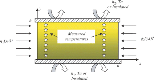
The specimen is a rectangular plate heated by two unknown heat fluxes at the active opposite surfaces. The others sides are insulated or submitted to convection heat transfer with the ambient ().
Figure 1. Presentation of the physical model.
The following hypotheses have been taken into account:
| • | Thermo-physical properties are assumed to be constant, | ||||
| • | Heat transfer is two dimensional, | ||||
| • | Heat fluxes are variable with space and time. | ||||
This information, together with the models (1–6), is used to solve the inverse problem.
3. Inverse problem
To build a computational algorithm, we use the variational formulation of the inverse problem of interest. The problem is to find unknown functions q1(y, t) and q2(y, t) for which temperature histories computed from the mathematical models (1–6) at the sensor locations would be close to measured histories. This leads to the problem of minimizing the residual functional:
(8)
where T(Xn, Yn, t; q1, q2), n = 1, 2, …, N, are temperature histories computed at the sensor locations with given heat fluxes q1(y, t) and q2(y, t).
The unknown functions are parametrized in the form of a cubic B-spline:
(9)
where pinm, n = 1, 2, …, My, m = 1, 2, …, Mt, i = 1, 2, are unknown parameters, ϕn(y), ϕm(t), n = 1, 2, …, My, m = 1, 2, …, Mt, are given basis cubic B-splines. The numbers of approximation parameters My and Mt are usually fixed a priori. As a result, the inverse problem is reduced to the estimation of a matrix pi, i = 1, 2 of parameters pinm, n = 1, 2, …, My, m = 1, 2, …, Mt.
The unknown functions are considered as an element of the function space L2([0, b] × [0, tf]) of parameterized functions. We use the unconstrained conjugate gradient method of optimization. The residual functional gradient as well as the descent direction in L2 space has the form:
(10)
(11)
So, the gradient is characterized by the two matrices gi = (ginm), i = 1, 2 and the descent direction by the two matrices di = (dinm), i = 1, 2, n = 1, 2, …, My, m = 1, 2, …, Mt. It is easy to show that the residual functional minimization with respect to desired parameterized functions is reduced to those with respect to unknown parameters. The successive improvements of desired parameters are constructed as follows:
(12)
where k is the iteration index,
is the descent parameter,
, is an initial guess for the matrix of unknowns parameters given a priori. Each matrix
, is computed as follows:
(13)
where
(14)
(·, ·) is the scalar product and |..| the norm in the in L2 space.
The realization of the iterative procedure (12) is based on computing the matrix gi, i = 1, 2, at each iteration. This matrix is determined by the relationship for the residual functional variation:
(15)
where
, is the residual functional gradient in RMy × RMt space of approximation parameters and
, is the gradient in L2 space of parametrized functions.
By using the parametric form (9), it can be shown that the matrix gi, i = 1, 2 is computed as follows Citation1:
(16)
where G is the Gram matrix for basis functions defined by:
(17)
The most effective method for calculating the gradient
, in RMy × RMt space is based on introducing an adjoin problem. The following expression for the gradient components can be derived:
(18)
where x1 = 0 for the first boundary condition and x2 = a for the second boundary condition and ψ(x, y, t) is the solution of the following adjoint problem, Citation3:
(19)
(20)
(21)
(22)
(23)
(24)
, is the descent parameter computed from the temperature variation for each heat flux and estimated by a linear approximation of the residual functional. The optimal value of the vector
is obtained by the minimization of the problem:
(25)
and by solving the following two-dimensional matrix system:
(26)
where
and
ϑi(x, y, t), i = 1, 2, is the solution of the following boundary-value problem for temperature variations Citation3:
(27)
(28)
(29)
(30)
(31)
(32)
where the descent directions D2(y, t) = 0 for i = 1 and D1(y, t) = 0 for i = 2, are computed in L2 space of parametrized functions.
To obtain stable solutions of the inverse problem, the iterative regularization method is used Citation3. The main idea is to terminate the iterative procedure when the residual criterion is satisfied:
(33)
where δ2 is the total (integrated) measurement error defined by:
(34)
σn²(t) is an estimate of the time-dependent SD for the nth measured temperature history. This procedure gives the most stable solution. The number k* of the last iteration is the regularization parameter of the method.
It is necessary to note that the numbers of approximation parameters My and Mt should be correctly chosen for the desired function. These numbers have to be chosen so that the residual criterion would be verified.
One iteration of the numerical algorithm includes the following steps:
| • | Solution of the direct problem and computation of the residual functional, | ||||
| • | Verification of the residual criterion, | ||||
| • | Solution of the adjoint problem and computation of the residual functional gradient in L2 space, for each unknown heat flux, | ||||
| • | Computation of the descent direction for each heat flux boundary condition, | ||||
| • | Solution of the problem for temperature variations and computation of the optimal descent parameter for each boundary condition, | ||||
| • | Calculation of the two estimated heat fluxes. | ||||
4. Numerical results and discussion
To simulate the numerical solution, we supposed in the problems (1–6) that: λ = 1 W m−1°C−1, α = 1 m2 s−1, a = b = 1 m, T0 = Ta = 0°C, h1 = h2 = 10 W m−2°C−1.
The measured temperature histories were simulated numerically and uniformly distributed inside the specimen on two lines (Lα) and (Lβ) parallel to the active surfaces and defined, respectively, by the coordinates (xα, yj) and (xβ, yj), yj = jΔy, j = 1, …, N/2, xα = αΔx, xβ = βΔx, Δx = (a/Nx − 1),Δy = (b/Ny − 1),Nx = Ny = 11.
A random noise of bx\% in the maximal temperature value is applied to the simulated temperatures.
The alternative direction implicit method (ADI) is used to solve the different boundary problems.
In the first test case, we have assumed:
(35)
where
The exact and estimated heat fluxes are presented respectively in ). The estimated results are obtained for the following conditions:
Figure 2. (a) Exact heat flux, q1(y, t) = q2(y, t). (b) Estimated heat flux q1(y, t). (c) Estimated heat flux q2(y, t).
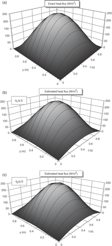
Number of the sensors: N = 12,
Position of the first line (Lα): xα = Δx,
Position of the second line (Lβ): xβ = 9Δx,
The sensors are uniformly distributed on every line.
Random noise: bx = 1%.
Numbers of the parameters in the y direction My = 11
Numbers of the parameters in time Mt = 51.
For all numerical tests presented in this article, the initial matrix , i = 1, 2, of the of unknowns parameters, in the iterative algorithm (12), is assumed to be equal to zero.
A good agreement exists at the final time between exact and estimated heat flux and temperatures. A small difference is shown, during the intermediate transient regime, in the y direction close the boundaries y = 0 and y = b.
In the following steps, we present a parametric analysis of the numbers of the parameters Mt and My for three numbers of the sensors N = 8, 12 and 22 and then, for an optimal choice of these parameters, we present the influence of the sensor locations for symmetrical and non-symmetrical positions of lines (Lα) and (Lβ), as well as the influence of the noise in measurement on the estimated results. Then, we finish this study by presenting some examples where the two boundary heat fluxes are different.
4.1. Influence of the number of the parameter Mt
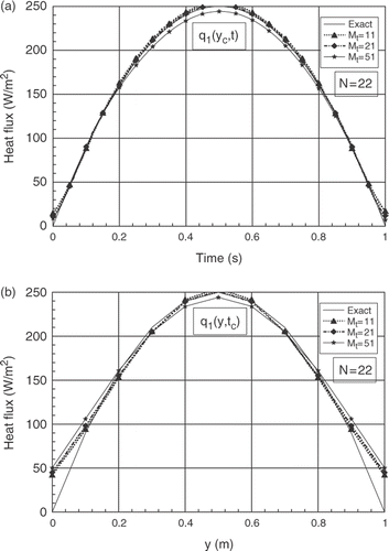
For My = 11, (xα, xβ) = (Δx, 9Δx), b = 1%, and for N = 8, 12 and 22, we present the influence of the number of the time parameters Mt(=11, 21 and 51). The analysis of the results shows a few differences between the exact and the estimated results for the three values of Mt. The main differences are observed in the spatial distribution close the boundary y = 0 and y = 1, respectively on the first and the final spatial grids. The case Mt = 11 gives some best results for the three numbers of sensors studied, see for N = 8, for N = 12 and for N = 22. The same remarks are observed for the second boundary heat flux q2(y, t).
Figure 3. (a) Evolutions of exact and estimated heat fluxes q1(yc, t) at yc = b/2, for N = 8 and different numbers of parameter Mt. (b) Exact and estimated profiles of q1(y, tc) at time tc = 0.5 tf, for N = 8 and for different numbers of parameter Mt.
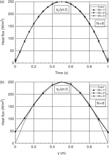
Figure 4. (a) Evolutions of exact and estimated heat fluxes q1(yc, t) at yc = b/2, for N = 12 and different numbers of parameter Mt. (b) Exact and estimated profiles of q1(y, tc) at time tc = 0.5 tf, for N =12 and for different numbers of parameter Mt.
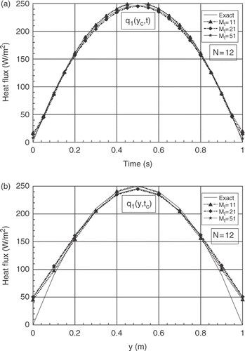
Figure 5. (a) Evolutions of exact and estimated heat fluxes q1(yc, t) at yc = b/2, for N = 22 and different numbers of parameter Mt. (b) Exact and estimated profiles of q1(y, tc) at time tc = 0.5 tf, for N = 22 and for different numbers of parameter Mt.
4.2. Influence of the number of the parameter My
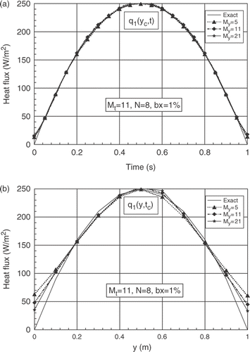
The analysis of this parameter, presented in , shows that a good agreement, between exact and estimated results for My = 11 or My = 21. The temporal evolution of the estimated heat fluxes seems nearly perfect for the three studied values of My whereas their spatial distribution improves as My increases, in particular to the neighbourhood of the limits y = 0 and y = 1. It is necessary to note, however, that for My > 11, the estimated results present some fluctuations that imply some differences superior to those observed with My = 11.
Figure 6. (a) Evolutions of exact and estimated heat fluxes q1(yc, t) at yc = b/2, for N = 8 and different numbers of parameter My. (b) Exact and estimated profiles of q1(y, tc) at time tc = 0.5 tf, for N = 8 and for different numbers of parameter My.
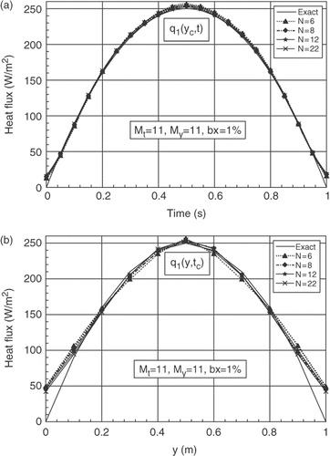
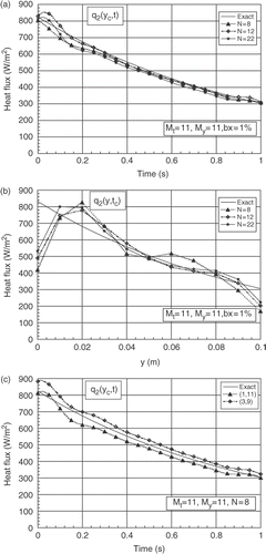
4.3. Influence of the number of the sensors
For the four cases studied (N = 6, 8, 12 and 22), the coordinates yj = jΔy of the sensors, for each line (Lα)α = 1 or (Lβ)β = 9, are defined in .
Table 1. Position yj of the sensors for N = 6, 8, 12 and 22
Through this parametric study and the analyse of the influence of the number of the sensors, (), we have chosen for the next numerical tests Mt = 11, My = 11 and N = 8.
Figure 7. (a) Evolutions of exact and estimated heat fluxes q1(yc, t) at yc = b/2, for different numbers of the sensors N. (b) Exact and estimated profiles of q1(y, tc) at time tc = 0.5 tf, for different numbers of the sensors N.
4.4. Influence of the sensor locations
For bx = 1%, the estimated results are presented in , for three symmetrical positions (xα, xβ), β = Nx − α, of the two sensor lines. The corresponding delta Fourier numbers (ΔFo1 = (αΔt/xα²), ΔFo2 = (αΔt/(a − xβ)²)) and the residual criterion δ2 are presented in .
Figure 8. (a) Evolutions of exact and estimated heat fluxes q1(yc, t) at yc = b/2, for different symmetrical positions of the sensors. (b) Exact and estimated profiles of q1(y, tc) at time tc = 0.5 tf, for different symmetrical positions of the sensors.
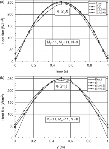
Table 2. Delta Fourier numbers and residual criterions for different positions of the sensor lines
The results show a perfect agreement between the evolution of exact and estimated heat fluxes for the first position (0, 1) and the second position (0.2, 0.8). Good agreement is noted also between the distributions of the exact and estimated heat fluxes q1(y, tc) except close to the boundaries y = 0 and y = 1. The second estimated heat flux q2(y, t) presents the same behaviour. The other curves show that the errors of the estimated results increase naturally when the positions of the sensor lines increase from the active surfaces of the specimen.
For the same conditions described above, we present in , the estimated results for non-symmetrical positions of the sensor lines (Lα) and (Lβ). The analysed positions are presented in .
Figure 9. (a) Evolutions of exact and estimated heat fluxes q1(yc, t) at yc = b/2, for different non-symmetrical positions of the sensors. (b) Evolutions of exact and estimated heat fluxes q2(yc, t) at yc = b/2, for different non-symmetrical positions of the sensors.
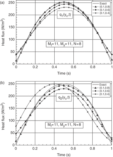
Table 3. Delta Fourier numbers for different positions of the sensor lines
The results show that the estimation of the heat flux q1(y, t) is better than the heat flux q2(y, t) and explain the importance of the position of the sensors towards the active surfaces. It should be noted that the results obtained in this case for the first heat flux q1(y, t) are worse than those obtained with a symmetric configuration. This difference is explain by the fact that the estimations of the heat flux q1(y, t) are affected by those obtained for q2(y, t).
4.5. Influence of noisy data
We present in , for sensor lines’ positions (0.1, 0.9), N = 8, ΔFo1 = ΔFo2 = 1, the estimated heat flux q1(y, t) for three values of random noise bx = 1, 3 and 5% of the maximal value of the simulated temperature. The corresponding residual criterions are presented in .
Figure 10. (a) Evolutions of exact and estimated heat fluxes q1(yc, t) at yc = b/2, for different measurement errors. (b) Distributions of exact and estimated heat fluxes q1(y, tc) at time tc = 0.5 tf, for different measurement errors.
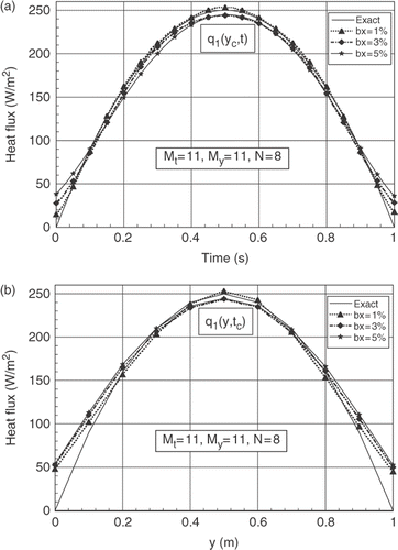
Table 4. Residual criterion for different random noises
The results show good agreement for small values of noise and the errors increase according to the noise. It is noted that the criterion of the iterative regularization method makes it possible to obtain acceptable and stable results for the amplitude of the noise imposed on the measured temperatures. The second estimated heat flux q2(y, t) shows the same behaviour.
4.6. Numerical tests for cases q1(y, t) ≠ q2(y, t)
4.6.1. First example: q1(y, t) = q0 f(y)g(t) and q2(y, t) = 0.25q1(y, t)
shows a comparison between the exact and the estimated heat fluxes q1(y, t) and q2(y, t) for symmetrical position P1(0.1, 0.9) and non-symmetrical position P2(0.3, 0.9), with bx = 1% and N = 8.
Figure 11. (a) Evolutions of exact and estimated heat fluxes for two positions of the sensors (first example). (b) Distributions of exact and estimated heat fluxes for two positions of the sensors, (first example).
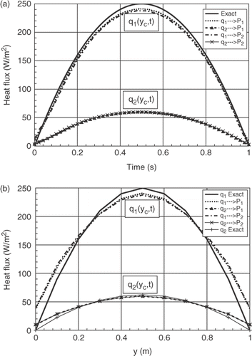
One finds the same remarks described above, i.e. as best estimate of the heat flux conditions nearest to the sensors. Here, the second heat flux presents a better estimate whereas that of first heat flux is less, since the first line of the sensors is further away from the surface condition being estimated.
4.6.2. Second example: q1(y, t) = q0 f(y)g(t) and q2(y, t) = q0 f(y)h(t), h(t) = (1 + cos(ωt)), ω = 15.7 rd/s
The same remarks are illustrated in , where we present in the same conditions, for non-symmetrical positions (0.3, 0.9), a comparison between exact and estimated results for the case where the form of the curve of q2(y, t) is different than that of q1(y, t) defined by (35).
Figure 12. (a) Evolutions of exact and estimated heat fluxes q2(yc, t) at yc = b/2 (second example). (b) Distributions of exact and estimated heat fluxes q2(y, tc) at tc = 0.5 tf (second example).
4.6.3. Third example: q1(y, t) = q0 sin [(y/b)(1 − (y/b))]exp(−(t/tf)) and q2(y, t) = q0 exp(1 − (y/b))exp(−(t/tf)), q0 = 500 W m−2
In this case, the analyse in function of the number of the sensors, for q1(y, t) and for q2(y, t), shows that the best results are obtained for higher value of N (N = 22), in particularly, in the spatial distribution where the relative minimum and maximum errors are, respectively, equal to 10% for N = 22 and 25% for N = 8. For each case, the maximum errors are located near the boundaries y = 0 and y = 1.
Figure 13. (a) Evolutions of exact and estimated heat fluxes q1(yc, t) at yc = b/2, for different numbers of the sensors, (third example). (b) Distributions of exact and estimated heat fluxes q1(y, tc) at time tc = 0.5 tf, for different numbers of the sensors, (third example).
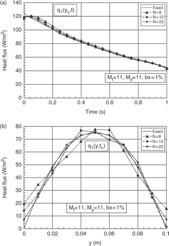
Figure 14. (a) Evolutions of exact and estimated heat fluxes q2(yc, t) at yc = b/2, for different numbers of the sensors, (third example). (b) Distributions of exact and estimated heat fluxes q2(y, tc) at time tc = 0.5 tf, for different numbers of the sensors, (third example). (c) Evolutions of exact and estimated heat flux q2(yc, t) at yc = b/2, for two positions of the sensors.
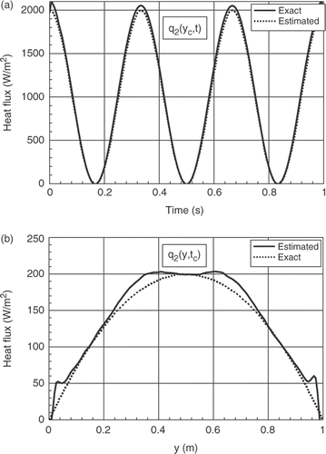
4.6.4. Fourth example: estimation of heat transfer coefficient
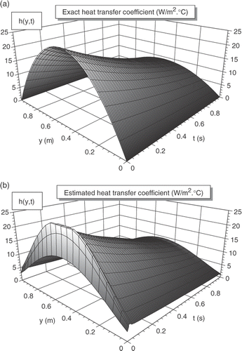
In this example, we present an example of the estimation of heat transfer coefficient for the case: h1(y, t) = h0 sin[(y/b)(1 − (y/b))]exp(−(t/tf)), h0 = 100 W m−1°C−1, h1(y, t) = h2(y, t) (). The estimated heat transfer coefficient, , is obtained in the following conditions: number of the sensors N = 16, positions of the sensor lines (0.1, 0.9), numbers of parameters Mt = 61, My = 11. The main difference between the exact and the estimated heat transfer coefficient is observed, as in the preceding other cases, in the vicinity of the boundaries y = 0 and y = b = 1 of the plate and especially, at the first instants of the transient regime, elsewhere, the results give better estimation.
Figure 15. (a) Exact heat transfer coefficient. (b) Estimated heat transfer coefficient.
5. Conclusion
An inverse method is used for to estimate the unknown surface heat fluxes from temperature data measured at two lines parallel to the heated surfaces of a rectangular plate. The functional form of the unknown surface conditions is unknown a priori. The numerical algorithm of this inverse heat conduction problem is based on the iterative regularization method and on the conjugate gradient method. For each boundary heat flux, a descent parameter is computed and an optimal choice of the matrix of the descent parameters is used and this shows an increase in the convergence rate.
The present estimates exhibit stable and accurate results and agree with the exact surface boundary conditions. Results also show that the accuracy of the estimated results decreases when the positions of the sensor line (or with delta Fourier numbers (ΔFo ≤ 0.05)) increase from the unknown heated surface and also when the noise of measurement (or simulated) temperatures increases. Other results show a good agreement between exact and estimated results for different distribution forms (constant, sinusoidal, etc.) and in the case where the evolution of the distribution of the two unknown heat fluxes is different.
References
- Tikhonov, AN, and Arsenin, AV, 1977. Solution of Ill-posed Problems. New York: Wiley; 1977.
- Beck, JV, Blackwell, B, and St. Clair, CR, 1985. Inverse Heat Condition: Ill-Posed Problems. New York: Wiley Intersc.; 1985.
- Alifanov, OM, Artyukhin, EA, and Rumyantsev, SV, 1995. Extreme Methods for Solving Ill Posed Problems with Applications to Inverse Heat Transfer Problems. New York: Begell House, Inc.; 1995.
- Zabaras, NK, Woodbury, KA, and Raynaud, M, 1993. Proceedings of the First International Conference on Inverse Problems in Engineering: Theory and Practice. Florida, USA: ASME, Palm Coast; 1993.
- Delaunay, D, Jarny, Y, and Woodbury, KA, 1996. Proceedings of the 2nd International Conference on Inverse Problems in Engineering: Theory and Practice. France: ASME, Le Croisic; 1996.
- Woodbury, KA, 1999. Proceedings of the 3rd International Conference on Inverse Problems Engineering: Theory and Practice. Washington, USA: ASME, Port Ludlow; 1999.
- Orlande, HRB, 2002. Proceedings of the 4th International Conference on Inverse Problems Engineering: Theory and Practice. Brasil: Rio de Janeiro; 2002.
- Chen, HT, et al., 2002. Estimation of two-sided boundary conditions for two dimensional inverse heat conduction problems, International Journal of Heat and Mass Transfer 45 (2002), pp. 15–23.
- Hsu, PT, Yang, YT, and Chen, CK, 1990. Simultaneously estimating the initial and boundary conditions in a two dimensional hollow cylinder, International Journal of Heat and Mass Transfer 33 (1990), pp. 621–628.
- Loulou, T, and Artioukhine, E, 2003. Optimal choice of descent parameter in gradient-type methods when applied to combined parameter and function or multi-function estimation, Inverse Problems in Engineering 11 (4) (2003), pp. 273–288.