Abstract
This article presents a numerical solution technique for shape optimization problems of steady-state, 3D viscous flow fields. In a previous study, the authors formulated shape optimization problems by considering the minimization of total dissipation energy in the domain of a viscous flow field, proposing a solution technique in which the traction method is applied by making use of a shape gradient. This approach was found to be effective for 2D problems for low Reynolds number flows. In the present study, the validity of the proposed solution technique is confirmed by extending its application to 3D problems.
1. Introduction
Shape optimization problems, in which the total dissipation energy in a channel used for the transportation of viscous fluid or the drag-power of a moving body in a viscous fluid is minimized, are important engineering problems from the viewpoint of increasing energy efficiency. From a morphological point of view, the solution of these problems provides a basis for understanding the shapes of vascular branches of living things, such as plants and animals.
The theory of shape optimization for incompressible viscous flow fields was initiated by Pironneau Citation1–3, who formulated a shape optimization problem for an isolated body located in a uniform viscous flow field to minimize the drag-power on this body. The distributed shape sensitivity, which was called the shape gradient, was derived with respect to domain variation by means of an adjoint variable method based on optimal control theory. The adjoint variable method introduces adjoint variables into variational forms of the governing equations as variational variables, and determines the adjoint variables using adjoint equations derived from criteria defining an optimality condition with respect to domain variation. In the viscous flow field problem, the inclusion of the adjoint equations necessitates an analysis of an adjoint fluid velocity and an adjoint pressure, in addition to the governing equations, i.e. the Navier–Stokes equations and the continuity equation for the fluid velocity and pressure.
In subsequent work, Glowinski and Pironneau Citation4 presented numerical solutions of the minimum-drag profile of a 2D body located in laminar flow using a boundary-layer splicing method, i.e. an inviscid/viscid patching method. Independently of this research group, for many years Jameson Citation5,Citation6 has also advocated and used control-theory techniques in the aerodynamic design of computational fluid dynamics using a continuous adjoint variable method.
Sano and Sakai Citation7 and Ganesh Citation8 analysed 2D shape optimization problems of an isolated body for Stokes flow fields using the numerical procedure proposed by Pironneau Citation3, in which degrees of freedom of the finite element nodal points on the isolated body's surface are chosen as design variables. They obtained an elliptical shape as the optimal shape. Ganesh Citation8 analysed a similar problem at a Reynolds number of 20, and obtained an ovoid, whose sharp end was pointed towards the upstream direction of the flow in the optimal shape. Huan and Modi Citation9,Citation10 analysed similar isolated body problems at a high Reynolds number, solving the original governing equations and adjoint equations using modified boundary conditions. Specifically, they replaced the Dirichlet outflow conditions with less restrictive Neumann outflow conditions.
All the studies introduced above made use of general gradient-based optimizations, such as the steepest descent method, based on the shape sensitivity for the discrete model. These methods, however, present the disadvantage of the large computational calculation time required for optimization processing when the number of the degrees of freedom for the finite element model increases. In addition, the mesh of internal nodes had to be refined in the process of updating the shape.
The present authors have proposed an approach for the optimization of the shape of such channels or bodies based on a gradient method using the distributed shape sensitivity, which we called the shape gradient, with respect to domain variation. In previous studies Citation11,Citation12, the present authors presented a numerical method for the minimization of the dissipation-energy of steady-state viscous flow fields, and applied this method to 2D problems.
The present study describes the extension of this method for application to the shape optimization of 3D viscous flow fields including convection terms. Reshaping was accomplished using the traction method Citation13–15, which was proposed as a means of solving boundary-shape optimization problems of domains in which partial differential equations must be solved subject to boundary value conditions. In the traction method, domain variations that minimize the objective functional are obtained as solutions of pseudo-linear elastic problems of continua defined in the design domain. These continua are loaded with pseudo-distributed traction in proportion to the shape gradient in the design domain. Both the evaluation of the shape gradient and the solution of the pseudo-linear elastic problems evaluating the domain variation can be obtained numerically using the finite-element method. Use of this numerical method makes it possible to apply the traction method to complex shape optimization problems with a large number of design variables, as in the case for 3D problems. In addition, since the traction method is implemented by means of the finite-element method, it is exceptionally easy to perform and offers the advantage that it is not necessary to refine the mesh of the internal nodes of the domain. The shape is updated in the traction method by modifying the displacements in the pseudoelastic body loaded with traction in proportion to the shape gradient. Thus, the present technique avoids the distortions that are observed in conventional shape optimization analyses caused by the movement of their internal finite element meshes.
In this article, a dissipation-energy minimization problem for viscous flow fields is considered. Based on the formulation of the shape optimization problem, the governing equations for calculating the shape gradient are derived using the adjoint variable method, the Lagrange multiplier method and the material derivative. Finite-element methods are used to obtain numerical solutions for the viscous flow fields, the adjoint equations and the reshaping by the traction method. Lastly, the validity of this numerical method is confirmed by application to several fundamental 3D problems.
2. Domain variation
Before formulating the shape optimization problem, we first briefly discuss a method of representing domain variation using the speed method. A more detailed explanation of this technique is given in Citation16.
Consider a domain Ω ⊂ Rn, where n = 2 or 3 and R is the set of real numbers. The boundary of Ω, Γ, is variable. One approach to describe the domain variation is to use a one-parameter family of one-to-one mappings Ts(X) : Ω ∋ X ↦ x ∈ Ωs, where s denotes the domain variation history.
Consider a domain functional JΩ of a distributed function φ. Denoting the derivative of such a functional with respect to s by , then the value of this derivative at s = 0 is given by the material derivative:
(1)
where ν is an outward unit normal vector on the boundary. The shape derivative, φ′, of the distributed function φ denotes the derivative of this function under a spatially fixed condition. The derivative of Ts(X) with respect to s is given by
(2)
and is called the velocity due to the analogy between s and time.
3. Minimization of the total dissipation energy of a viscous flow field
Let us consider a steady-state viscous flow field of an incompressible Newtonian fluid in domain Ω ⊂ Rn with boundary Γ = Γ0 ∪ Γw ∪ Γ1. Let fluid velocity be bounded with a prescribed fluid velocity û ∈ (H1/2(Γ0))n on an inhomogeneous Dirichlet-type sub-boundary Γ0, and let u = 0 on a homogeneous Dirichlet-type sub-boundary Γw:
(3)
and satisfy the boundary condition
(4)
with a prescribed force
on a Neumann-type sub-boundary Γ1. Let pressure p ∈ Q where
(5)
The density ρ ∈ L∞(Ω) and co-efficent of viscosity μ ∈ L∞(Ω) are assumed to be given.
3.1. Formulation of problem
The total dissipation energy minimization problem under volume constraint M > 0 is formulated as:
(6)
(7)
(8)
(9)
(10)
(11)
where Equations (9) and (10) are variational forms, or weak forms, using the adjoint velocity
, where
(12)
and the adjoint pressure q ∈ Q for the governing equations, i.e. the Navier–Stokes equations and the continuity equation. Equation (11) describes the volume constraint. The viscous term aV(u, w), the convective term b(v, u, w), the pressure term c(w, p), and the stress term d(w) are defined by
(13)
(14)
(15)
(16)
where
. The Einstein summation convention and partial differential notation (·),i = ∂(·)/∂xi are used in the tensor notation of this article.
3.2. Shape gradient
Applying the Lagrange multiplier and adjoint variable methods, this problem can be transformed into a stationary problem of the Lagrange functional L(u, p, w, q),
(17)
where w ∈ W and q ∈ Q are the adjoint variables with respect to the fluid velocity and the pressure, respectively. The non-negative real number Λ is the Lagrange multiplier with respect to the volume constraint.
Imposing the condition that the inhomogeneous Dirichlet-type sub-boundary Γ0 and the Neumann-type sub-boundary Γ1 are invariable under reshaping allows the derivative of L with respect to s, , to be simply expressed as:
(18)
where
is the material derivative, and (·)′ is the shape derivative for the domain variation of the distributed function under a spatially fixed condition. The linear form ⟨ Gν, V ⟩ with respect to the velocity function V is given by
(19)
(20)
(21)
Considering stationary conditions for the variables w′ ∈ W, q′ ∈ Q, u′ ∈ W and p′ ∈ Q appearing in Equation (18), the Kuhn–Tucker conditions with respect to u, p, w, q are obtained as
(22)
(23)
(24)
(25)
(26)
with Equations (22–25) describing variational forms of the original governing equations for fluid velocity u and pressure p, and variational forms of the adjoint equations for adjoint velocity w, and adjoint pressure q, which we call adjoint equations. If Equations (22–26) are satisfied, the derivative of the Lagrange functional agrees with that of the objective functional and the linear form ⟨ Gν, V ⟩ with respect to the velocity function V:
(27)
The coefficent vector Gν in Equation (19) represents the sensitivity of the velocity function to domain variation, and is called the shape gradient. The scalar function G is called the shape gradient density.
4. Numerical solution technique
4.1. Traction method
If the shape gradient is obtained, the traction method Citation13–15 can be applied to optimize the geometrical domain shape. The traction method has been proposed as a procedure for solving the velocity V ∈ D by
(28)
where aE(·, ·) is defined by
(29)
and
where {Aijkl}i, j,k,l=1,2, …, n,
and
denote an elastic tensor, displacement and variational displacements, respectively. Equation (28) indicates that the velocity V decreasing in the objective functional, that is the dissipation energy in this study, is obtained as a displacement of a pseudo-elastic body defined in Ω by the loading of a pseudo-external force in proportion to −Gν, under constraints on the displacement of invariable boundaries. The robustness of the traction method to oscillating phenomena, which often occur at the moving boundary nodes of finite-element models in proportion to the negative value of the shape gradient, has been confirmed theoretically Citation14.
4.2. Numerical procedure
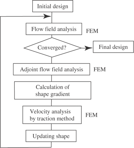
A flow chart of the shape optimization system is shown in . Finite-element methods were employed in all the analysis steps of the system. Shape optimization analysis was performed by executing these elements sequentially and repeatedly.
The shape gradient was evaluated using the two viscous flow-field analyses, which obtain distributions of fluid velocity u, pressure p solving the non-linear original governing Equations (22) and (23), and the distributions of adjoint fluid velocity w, and adjoint pressure q solving the linear adjoint Equations (24) and (25). For the case of 3D problems considered in this study, we used the Taylor–Hood elements in the finite-element analysis. That is, the complete polynomial series to the second-order terms was used to provide interpolation functions for u and w, while the linear polynomial series was used to provide interpolation functions for p and q. Further, a tetrahedral finite-element with 10 nodes for u and w and four nodes for p and q was also employed. The non-linear original governing Equations (22) and (23) were solved by the Newton–Raphson method.
The shape gradient was calculated using the results of these analyses. The domain variation V in Equation (28) was analysed using the finite-element method, using second-order finite-elements for V. The Lagrange multiplier Λ, determined so as to satisfy the volume constraint, can be regarded as a uniform surface force in the external force −Gν. Therefore, it should be possible to satisfy the conditions of Equation (26) by controlling the magnitude of this uniform surface force, Λ.
5. Numerical results
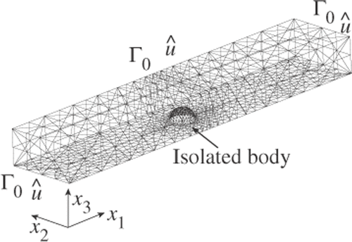
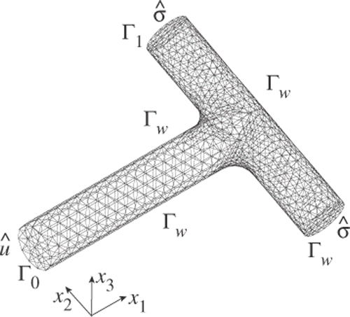
We present numerical results for two 3D low Reynolds number viscous flow problems: for an isolated body in uniform flow, and for a branch channel, as shown in and , respectively.
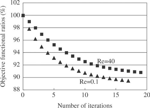
The FEM model and boundary conditions for the isolated body problem are shown in , where the design boundary was designated to be the surface boundary Γw of the isolated body. The Reynolds number is defined from the magnitude of the uniform flow û and the initial diameter of the isolated body. Symmetry about the channel centre-plane was also exploited for this problem, and the total numbers of nodes and elements are 10,681 and 6,484, respectively. and illustrate the results of the isolated body problem. On the basis of these results, we can observe that the optimal shape is ellipsoidal at Re = 0.1 (Stokes flow) and ovoid at Re = 40, where the sharp end points to the upstream direction of the flow. The numerical results for Stokes flow are in good agreement with the shape considered by Pironneau Citation1. The monotonic convergences of the iteration histories of dissipation energy in both problems confirm the validity of the proposed method.
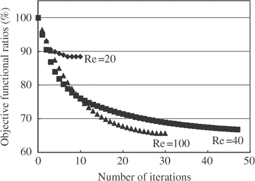
Regarding the configuration of the branch channel problem shown in , fluid flows in from a boundary Γ0 and flows out from two boundaries Γ1. Poiseuille flow û was assumed at the entrance boundary Γ0, and a prescribed force was assumed at the exit boundaries Γ1. The design boundary is given by the whole of the wall boundary Γw. The entrance boundary Γ0 and the exit boundaries Γ1 were restricted for the reshaping. The Reynolds number is defined from the mean of the Poiseuille flow û and the width at the entrance boundary Γ0. The total numbers of nodes and elements are 9229 and 5052, respectively. The numerical results of this problem at Re = 20, 40 and 100 are shown in and .
The values of the objective functional in both problems were converged, and thus we confirmed the validity of the present method.
6. Conclusions
In this article, we formulated a dissipation-energy minimization problem for steady-state viscous flow fields, and derived the shape gradient with respect to this problem. The validity of the traction method using the derived shape gradient was confirmed on the basis of the numerical results obtained by applying the method to two 3D shape optimization problems.
Acknowledgements
This study was financially supported by The Koshiyama Research Grant in Japan. We express our gratitude to Mr Naoshi Nishihashi, student of the Gifu National College of Technology, for his cooperation.
References
- Pironneau, O, 1973. On optimum profiles in Stokes flow, J. Fluid Mech. 59 (1973), p. 117.
- 1974. On optimum design in fluid mechanics, J. Fluid Mech. 64 (1974), p. 97.
- 1984. Optimal Shape Design for Elliptic Systems. New York: Springer-Verlag; 1984.
- Glowinski, R, and Pironneau, O, 1975. On the numerical computation of minimum-drag profile in laminar flow, J. Fluid Mech. 72 (1975), p. 385.
- Jameson, A, 1988. Aerodynamic design via control theory, J. Sci. Comput. 3 (3) (1988), p. 233.
- 1995. "Optimum aerodynamic design using control theory". In: Hafez, M, and Oshima, K, eds. Computational Fluid Dynamics Review 1995. New York: John Wiley & Sons; 1995. p. 495.
- Sano, M, and Sakai, H, 1983. Numerical determination of minimum drag profile in Stokes flow (in case of two-dimensional finite region and constant cross-sectional area), Trans. Jpn Soc. Aero. Sci. 26 (71) (1983), p. 1.
- Ganesh, RK, 1994. The minimum drag profile in laminar flow: a numerical way, Trans. ASME, J. Fluids Eng. 116 (1994), p. 456.
- Huan, J, and Modi, V, 1994. Optimum design of minimum drag bodies in incompressible laminar flow using a control theory approach, Inverse Probl. Eng. 1 (1994), p. 1.
- 1996. Design of minimum drag bodies in incompressible laminar flow, Inverse Probl. Eng. 3 (1996), p. 233.
- Katamine, E, and Azegami, H, 1995. "Domain optimization analyses of flow fields". In: Atluri, SN, Yagawa, G, and Cruse, TA, eds. Computational Mechanics'95. Vol. 1. New York: Springer; 1995. p. 229.
- Katamine, E, Azegami, H, Tsubata, T, and Itoh, S, 2005. Solution to shape optimization problems of viscous flow fields, Int. J. Comput. Fluid Dyn. 19 (2005), p. 45.
- Azegami, H, Shimoda, M, Katamine, E, and Wu, ZC, 1995. "A domain optimization technique for elliptic boundary value problems". In: Hernandez, S, and Brebbia, CA, eds. Computer Aided Optimum Design of Structures IV. Southampton: Computational Mechanics Publications; 1995. p. 51.
- 1997. "Irregularity of shape optimization problems and an improvement technique". In: Hernandez, S, and Brebbia, CA, eds. Computer Aided Optimum Design of Structures V. Southampton: Computational Mechanics Publications; 1997. p. 309.
- Azegami, H, 2000. "Solution to boundary shape identification problems in elliptic boundary value problems using shape derivatives". In: Tanaka, M, and Dulikravich, GS, eds. Inverse Problems in Engineering Mechanics II. Oxford: Elsevier; 2000. p. 277.
- Sokolowski, J, and Zolésio, JP, 1992. Introduction to Shape Optimization, Shape Sensitivity Analysis. New York: Springer-Verlag; 1992.
