Abstract
The flow of melted polyethylene (Dowlex 2042E) through an extrusion die is investigated both experimentally and numerically. This article deals with the reconstruction of thermal history of the melted polymer in the channel die and the influence of the extrusion parameters on the inlet temperature profile. The inverse heat transfer problem is formulated as an optimization problem by considering both the heat transfer and Navier-Stokes equations. It is solved by using the classical conjugate gradient algorithm. Experimental results are presented and the article focuses on the importance of checking the adequacy of the modelling equations in experimental data processing in order to avoid convergence of the inverse algorithm toward solutions which have no physical significance. The effects of the pressure drop combined with the viscous dissipation effect along the channel die are then discussed.
Nomenclature
| Cp | = | heat capacity (J kg−1°C−1) |
| F | = | source term of energy (Pa s−3) |
| J | = | functional to be minimized (°C2) |
| lc | = | length of the die connector (m) |
| lb | = | width of the zone (m) |
| lp | = | perimeter (m) |
| Lhp | = | length of the heating-plate (m) |
| Ns | = | number of sensors |
| P | = | pressure (Pa) |
| Q | = | flow rate (g s−1) |
| T | = | temperature (°C) |
| = | velocity (m s−1) | |
| u, v | = | axial and radial velocities (m s−1) |
| = | measure temperatures (°C) |
| c | = | connector |
| m, p | = | sensor locations |
| 0 | = | inlet extrusion die |
| hp | = | heating plate |
| melt | = | melted polymer |
| n | = | iteration number |
| n | = | vector normal |
| p | = | polymer |
| s | = | outlet extrusion die |
| w | = | die wall |
| = | shear rate (s−2) | |
| η | = | dynamic viscosity (Pa s) |
| λ | = | conductivity (W m−1°C−1) |
| ρ | = | density (kg m−3) |
| ψ | = | adjoint variable |
| θ | = | sensitivity variable |
| δ | = | dirac delta function |
| Ω | = | spatial domain |
1. Introduction
During polymer extrusion, even after the melting zone, heat transfer takes an important place at the outlet of the extruder Citation1,Citation2. Due to high viscous dissipation and very low heat conductivity, the temperature profile within the channel die can be quite sharp. Overheated areas can be generated and degradation of the polymer could occur. For such creeping flow the temperature field is affected far downstream from the entrance of the die, so to predict accurately and to control the temperature rise, the inlet temperature profile has to be taken into account. However, due to the history in the extruder, the material temperature at the die entrance is rarely uniform. Hence, the determination of this temperature profile is referred to as a boundary inverse heat convection–conduction problem. There are numerous works on the initial temperature profile restoration, for example, in Citation3 the inlet temperature profile is estimated in the laminar duct flow and subsequent investigations Citation4–6 examine various aspects of this problem. Recently, Hsu et al. Citation7 presented a two-dimensional inverse least squares method to estimate both inlet temperature and wall heat flux in a steady laminar flow in a circular duct. Huang and Chen Citation8 have solved a non-stationary Navier-Stokes equation, to provide coefficients for energy equation, but the velocity field does not depend on temperature. Gejadze and Jarny Citation9 have presented a detailed analysis of IHCP coupled problem, when the velocity field depends on temperature field through viscosity and Navier-Stokes equations for a non-Newtonian fluid. Recently, Nguyen and Prystay Citation10 estimated the initial temperature profile and its evolution in polymer processing using the surface temperature measurement and the conjugate gradient method was employed to search for the minimum of the functional. In a previous work Citation11 the authors studied the numerical resolution of such an inverse heat convection–conduction problem to estimate the temperature field within the polymer flow from temperature measurements taken inside the die wall. The solution was computed according to the classical conjugate gradient method [CGM]. An iterative numerical procedure was used to solve the direct, the adjoint and the sensitivity equations. The modelling equations for the fluid flow in the channel as well as for the heat flow within the melted polymer and the wall regions were solved simultaneously Citation12,Citation13. The melted polymer was considered as an incompressible pseudo-plastic fluid, and the flow was assumed steady and laminar. The sensitivity analysis led to important results to design the experimental die and to decide the thermocouple locations within the die Citation13. The method was validated using numerically generated data for different thermal and flow conditions Citation14. It was shown that the influence of the initial guess on the estimated inlet profile was very weak. In this article, the same inverse problem is considered and the same algorithm is used but the goal is to reconstruct the inlet polymer temperature profile within an experimental die channel. The article aims to show the importance of checking the model adequacy when experimental data have to be processed. In this problem, it is observed that the inverse algorithm cannot converge towards physical realistic solutions without modifying the heat conduction model equations. This modification consists of taking into account the lateral heat losses of the die. With these new model equations, the reconstructed inlet profile is satisfactory and consistent with a priori knowledge of the polymer flow.
2. Experimental device
2.1. Extrusion die and data acquisition system
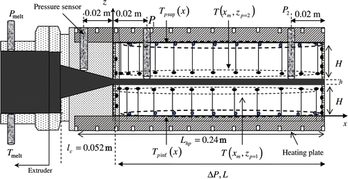
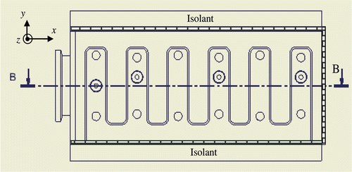
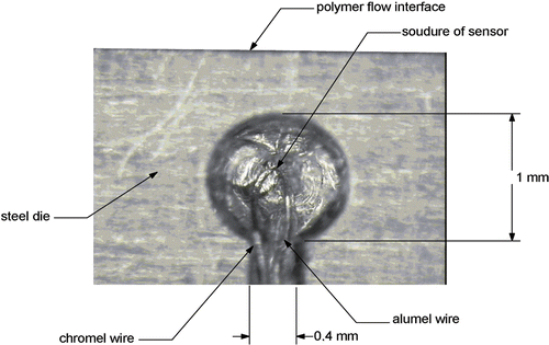
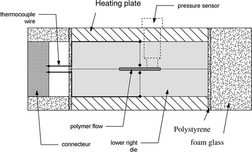
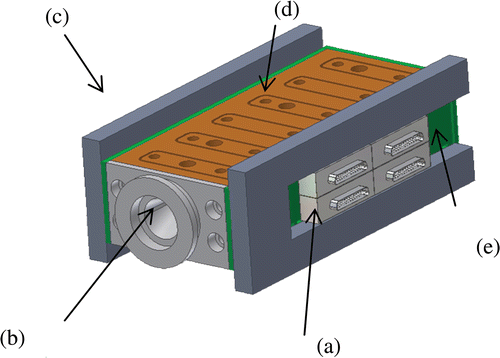
The main parts of the experimental extrusion die are described in and . A rectangular channel (0.002 × 0.03 m2) is connected to the extruder outlet through a cone of length lc = 0.051 m. The total channel length is Lch = 0.24 m. The channel walls are made of four stainless steel blocks, instrumented by thermocouples (K), length, thickness and width of each block are L = 0.2 m, H = 0.019 m and lb = 0.05 m. Two electrical heater plates ensure the heating of the die on its upper and lower faces. To reduce the lateral heat side losses of the die, a composite material (polystyrene, thickness: 0.002 m) and a porous material (foam-glass, thickness: 0.03 m) surround the non-heated side surfaces, except around the measurement connectors. The pressure Pmelt and the temperature Tmelt of the polymer are measured near the channel entrance (extruder outlet), both parameters give first information on the thermal state of the polymer. According to the previous numerical study Citation13,Citation14, heat transfer within the die and the channel was first assumed to be bi-dimensional (lateral heat losses were neglected) and only the median plane (B-B) of the extrusion die () is instrumented. The temperature is measured in several places of the upper and lower die walls by using 56 thermocouples K (Chromel–Alumel φ = 50 µm). The wires pass in grooves of 4 × 10⁻⁴ m of diameter. They are welded to metal in holes of 0.001 m of diameter. shows the accurate location of each welding. The locations of these thermocouples are specified as follows: 24 thermocouples are close to the upper and lower faces of the channel, 20 thermocouples are close to the upper and lower heating plates and 8 thermocouples are located at the outer face of the die.
Figure 1. Extrusion die (model 3D), (a) thermocouple connectors, (b) inlet of the die, (c) insulator, (d) heating plate, (e) composite material: polystyrene.
The measurements of inlet and outlet pressure in the channel are essential since they are used as boundary conditions of the mathematical model. The Dynisco melt pressure transducer for space-restricted areas is used to make pressure measurements of molten polymers up to 400°C. They incorporate a 350-ohm, bonded foil strain gage Wheatstone bridge. This proven technology provides an output of 0–3.33 mV/V (nominal), proportional to melt pressure (within the specified error band). All the measurements were numerically recorded using a high-speed data acquisition system (scanner HP 34970A and Nanovolt/Micro-ohm-meter type HP 34420A), controlled by a VEE-Pro software. The integration time is specified in a number of power line cycles (NPLC). For a steady flow and a better resolution, the longest time is used, i.e. NPLC = 10. The thermophysical properties of the metallic die are assumed to be constant in the temperature range of working: the thermal conductivity is λw = 16 W m−1 K−1.
2.2. Polymer properties
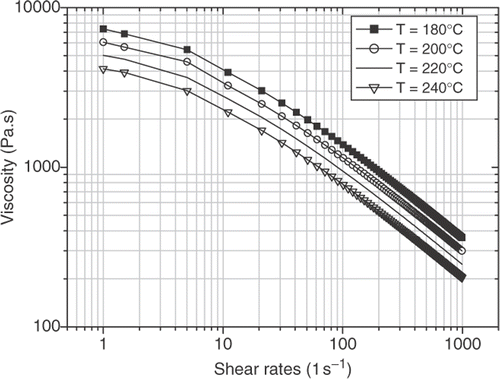
The melted polymer used in this work is a low-density polyethylene (LDPE Dowlex 2042E extrusion grade) suitable for the production of blow film. To measure the viscosity of PE material, we used two kinds of measuring apparatus: a capillary rheometer (Ceast Co., Italy) and Rubber process analyser (RPA 2000). We consider the shearing viscosity because flow pattern in a die extrusion of polymer melts is mainly shear flow. It is defined as the ratio of the local shear stress to the shear rate at that point. The viscosity function , is temperature and shear-rate dependent. The rheological properties were measured over the 177–237°C temperature range with shear rates varying from 0.1 s−1 to 1000 s−1. presents the melt flow curves at various temperatures. It can be seen that the logarithmic plots are quite similar in shape, showing the higher shear rate, the lower the shear viscosity. The shear viscosity irregularly decreases with increasing apparent shear rate, indicating a shear thinning (i.e. pseudoplastic) nature due to the random orientation and highly entangled state of the molecules which under high shear rate get disentangled and become orientated, leading to a reduction of viscosity Citation15. With a rise of temperature, the value of shear viscosity decreases, especially at relatively lower apparent shear rate, demonstrating that increasing temperature improves the flow behaviour of the polymer melts. However, the effect of temperature on shear viscosity changes with the shear rate. The data indicate that the temperature sensitivity of shear viscosity is higher in the lower shear rate region, and drops at higher shear rates. Determination of the viscosity curve, , over a wide range of shear rate values is essential for solving the flow Equations (3–9). The data measurements were fitted (inverse method) to the Cross WLF model (Equation 1). Thermal and rheological parameters of the PE are given in .
(1)
(2)
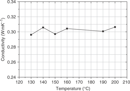
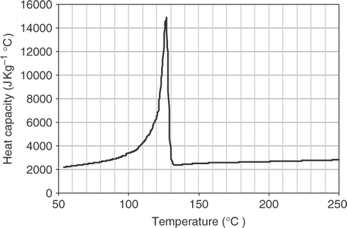
The thermal conductivity of the melted PE was measured under moulding conditions (high pressure and high temperature) using a specific experimental apparatus and a numerical method Citation14. The variation of thermal conductivity is shown in . Phase change occurs in the range [115°C, 130°C] and the maximum value of thermal conductivity is in the same temperature range. The heat capacity Cpp(T) () was measured with a differential scanning calorimeter (Pyris 6 DSC). Data measurements were fitted in the temperature range [150°C, 250°C]. The temperature-dependent heat capacity is represented by Equation 2.
Table 1. Thermal and rheological properties of PE Dowlex 2042E.
2.3. Experimental conditions and procedure
All the experiments were carried out with a single-screw extruder (screw diameter = 3 cm and length = 78 cm). The minimum and the maximum flow rates are 0.5 and 15 kg h−1 respectively, and the maximum rotation speed is 100 rpm. The polymer in the form of small pellets about 4–7 mm in size is fed from a hopper by gravity into the extruder. Flow rate is measured by weighing the mass of polymer exiting at the channel die outlet. The pressure drop (ΔP) along the channel die is measured by using two pressure sensors located at the inlet and outlet of the channel die. The transducers are rated at up to 80 MPa and are interfaced with the control system, which displays the polymer pressures. The heating units controlled the temperature of the upper and lower faces of the die. Several experiments on the PE Dowlex 2042E have been carried out at different pressures from 10 to 25 MPa. Some experimental conditions are listed in the .
Table 2. Polymer processing conditions of PE Dowlex 2042E.
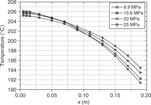
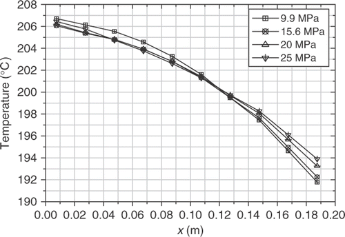
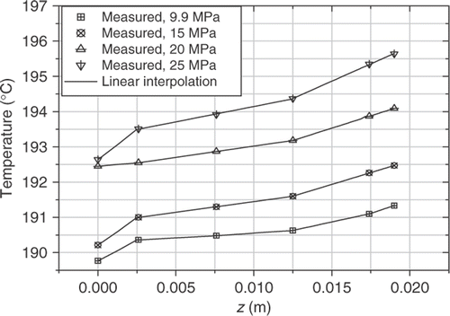
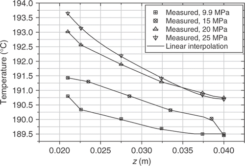
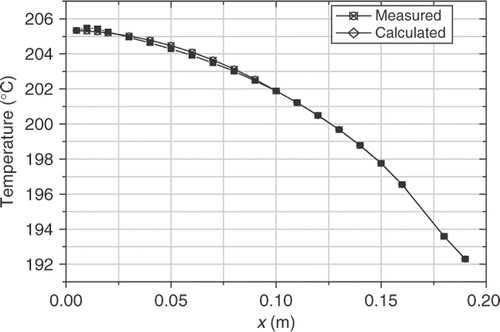
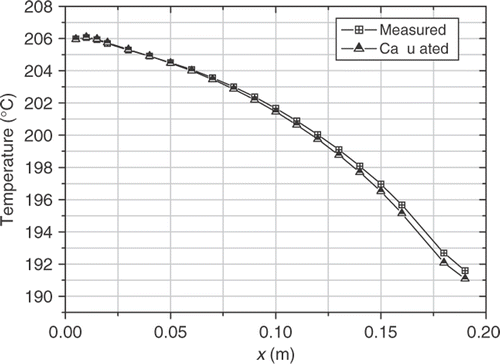
Figures and show the temperature profiles measured within the die wall in the flow direction, both near the channel and heating plates. The temperature is maximal at the die inlet and then decreases along the flow axis. This decrease results in non-controlled heat losses at the outer face of the die. But it can be observed that increasing the pressure drop in the channel raises the flow axis temperature profiles at the die outlet, near the channel. This temperature rise results in a shear heating effect within the polymer flow, which increases with the pressure drop. and show the thermal boundary conditions on the upper and lower faces, used in the modelling equations.
3. Mathematical modelling equations
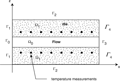
A steady laminar flow model of an incompressible polymer is considered. shows the 2D spatial domain (Ω = Ω1 ∪ Ω0) of the extrusion die in a median plane parallel to the flow direction.
The polymer melt enters the extrusion die at x = 0 with a temperature profile T0(z). The velocity and the temperature fields are governed by the coupled equations of mass, momentum and energy, i.e.
(3)
(4)
(5)
(6)
The term F is due to viscous dissipation. According to the rheological behaviour, this term can take various forms. In our study, it is given by:
(7)
The term Sp,w was not considered in the previous study, because heat losses through the connectors of the non-heated side face of the die were neglected. This new term is introduced here for taking into account the lateral heat side losses of the die. The lateral face is divided in four zones (straight rectangular fins) as shown in Figures , lp, lb and Szone are the perimeter, thickness and surface area of each fin (), respectively.
(8)
(9)
is a heat transfer coefficient for each zone. Their values are determined by the thermal theory of the rectangular fin with uniform cross section Citation16.
Figure 14. (a) Insulator (foam glass), (b) insulator (polystyrene), (c) die wall, (d) heat flux from melted polymer to the connectors and insulators, (e) aluminium to fix the connectors, (f) thermocouples, (g) connectors.
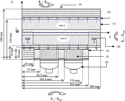
Figure 15. Zone heat loses: (a) polymer, (b) die wall, (c) composite: polystyrene (2mm) (d) aluminium and connectors, (e) foam-glass (30 mm).
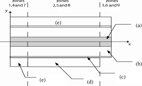
Table 3. Heat losses coefficients.
The following boundary conditions are then considered. For the velocity field:
| • | At the channel inlet:
| ||||
| • | At the channel outlet:
| ||||
| • | At the internal surface, (usual no-slip boundary condition):
| ||||
For the temperature field, the boundary conditions are taken as follows:
| • | At the channel entrance: | ||||
4. Inverse heat transfer problem
The inlet temperature profile T0(z) has to be determined from the temperature given by Ns sensors located inside the extrusion die wall at (xm, zp), m = 1, …, Ns/2, p = 1, 2. The inverse problem is formulated by considering the following least square criterion:
(18)
where T(xm,zp;T0) are the temperatures computed from the direct problem equations, at the measurement locations, with the fixed inlet temperature profile T0(z). The conjugate gradient method is used to search for the minimum of the functional. This method has been well documented elsewhere Citation14,Citation17,Citation18 and will not be repeated here. The method is based on the computation of the gradient of the functional, which is obtained by solving the sensitivity problem and the adjoint problem defined as follows.
4.1. The sensitivity problem
In order to develop the sensitivity problem equations, a variation ϵδT0 of the inlet temperature profile is considered, and the resulting temperature is denoted T(x, z; T0 + ϵδT0).
The sensitivity is then defined by Citation14,Citation17:
(19)
Developing the direct problem Equations (3–9) for T(x, z; T0) and T(x, z; T0 + ϵδT0) and then subtracting the resulting expressions leads to:
(20)
(21)
(22)
(23)
(24)
(25)
where
is the velocity profile in the channel die.
4.2. The adjoint problem
The following adjoint problem equations are obtained Citation14:
(26)
(27)
(28)
(29)
(30)
(31)
with
(32)
(33)
5. Results and discussion
The computational technique used to solve the direct problem is based on a finite volume method (FVM) discretization of the governing mass, momentum and energy equations. More details can be found in previous studies Citation13,Citation14. Comparisons between numerical and analytical solutions confirm the adequacy of the mesh grid size chosen for solving the modelling equations. The same numerical method and grids are used to solve the adjoint and the sensitivity problem. The feasibility and accuracy of the inverse analysis for estimating the unknown inlet distribution temperature, by using the CGM, was illustrated in several numerical experiments, including the case of non-Newtonian fluid Citation14.
5.1. Effect of heat losses in the model equations
First we will show the influence of the heat losses through the non-heated sides of the die, on the estimated inlet temperature profiles. Two sets of modelling equations are considered successively for solving the inverse problem: one by setting the lateral heat losses Sp,w(x, z; T) equal to zero, the other one by adding the heat losses Sp,w(x, z; T) according to Equation 8. In both cases, the iterative process is initialized with the uniform initial guess . In order to compare and to conclude about the validity of the estimated profiles that result from the minimization of the same criterion J(T0), Equation 18, it is necessary to take into account the magnitude of the error measurements in the stopping rule of the iterative process. The errors on the temperature data measured in the die wall are supposed to be zero mean, and Gaussian. The standard deviation is not exactly known, but it is less than σmax = 0.1 K and more than σmin = 0.05 K. Then, without errors in the modelling equations, the asymptotic value Js of the least square criterion J(T0), computed with Ns = 40 sensors, is expected to be in the following range: Js = Nsσ²⊂[0.1 K²,0.4 K²]. The stopping rule of the conjugate gradient algorithm used to minimize J(T0) must be consistent with this expected asymptotic range. It is clear that if the asymptotic value Js remains greater than the upper bound 0.4 K2, the assumption of the model adequacy has to be rejected. But on the contrary, when the value Js (almost) reaches this expected range, the adequacy of the modelling equations may be (almost) accepted. In practice, even in this favourable situation, the adequacy of the modelling equations remains imperfect, and the final value of Js cannot be predicted exactly. Therefore the iterative process is stopped when no significant decrease of J(T0) is observed within this expected range.
Case I: Model equations without heat losses, Sp,w(x, z, T) = 0
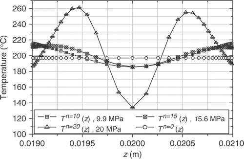
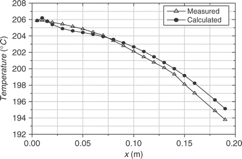
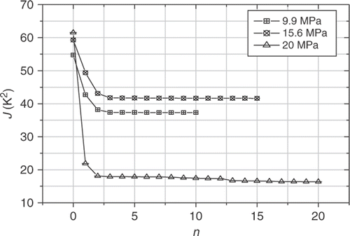
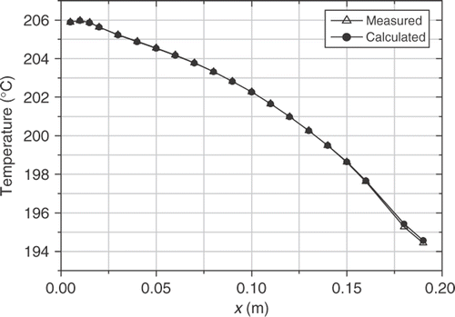
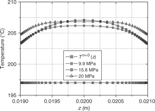
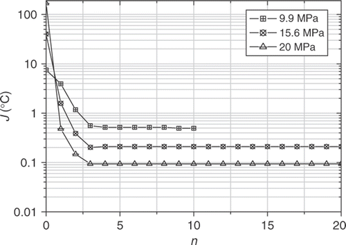
In , a comparison is made between the initial guess of the temperature profile and the reconstructed temperature profiles for different pressure drops. For three different operating conditions: ΔP = 9.9, 15.6 and 20 MPa. compares the measured and the calculated temperatures and shows the least square criterion J(T0) versus the iteration number n. It can be observed, for the three cases considered, that the asymptotic values Js are different but all of them are reached after n = 3 iterations and these values are greater than the above expected range. From these observations, we are forced to conclude that the modelling equations without heat losses are not able to accurately predict heat transfer in the die wall. The model is biased, and the estimated inlet profiles computed with this model are not acceptable. In fact, this conclusion is confirmed by the shape of the estimated profiles (), the temperature is very high near the walls (up to 260°C) and very low in the middle of the channel (130–187°C). These profiles have no physical significance. The hypothesis of the model adequacy is violated, and the resulting estimated inlet profiles strongly biased.
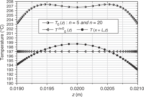
Case II: Model equations with lateral heat losses, Sp,w(x, z, T) ≠ 0
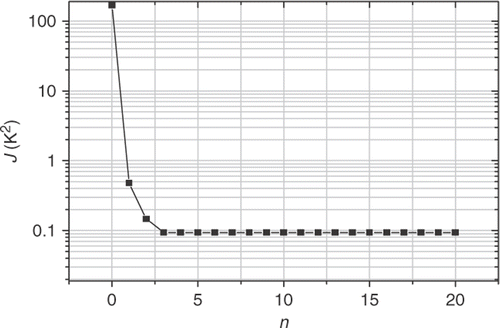
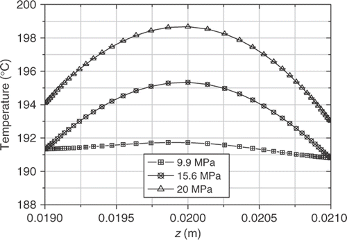
In , comparison is made between the initial guess of the temperature profile and the reconstructed temperature profiles for a pressure drop Pmelt = 20 MPa. It is observed in that the asymptotic value of the least square criterion in this case, is obtained after five iterations, and this value is very close to the best expected value Js = 0.1 K2. This result shows better adequacy of the new model equations (), because now this value is consistent with the standard deviation of the measurement errors. Moreover, the estimated temperature profiles of the polymer now have a physical meaning: it is observed that the mean temperature of the outlet profile is inferior to that of the inlet profile because of the heat losses through the non-heated faces of the die, but contrary to the inlet profile, the distribution of the outlet profile shows a maximum at the channel centre. These observations are consistent with the heat transfer phenomena which occur within the die wall and the polymer flow under viscous dissipation. These results are confirmed with the other experiments.
5.2. Effect of the flow rate on the inlet temperature (Sp,w(x, z, T) ≠ 0)
In these experiments, we varied the pressure drop ΔP = P0 − Ps (flow rate) along the channel die by increasing the screw rotation of the extruder. In all these cases, the temperature of the polymer in the inlet die-connector is strongly affected by both the screw rotation and the temperature of the screw heating-zones. When the screw rotation is 37 rpm, to keep a polymer temperature close to 200°C at the extruder outlet, the heating-zones temperature must be controlled to a low value equal to 193°C. shows the influence of pressure drops on the temperature profiles along the flow axis, near the heating plates. The temperature is maximal at the die inlet and then decreases slightly because of lateral heat losses.
and show the different estimated inlet temperature profiles according to the different pressure drops considered: ΔP = 9.9, 15.6 and 20 MPa. When the pressure drop increases, the flow rate increases and the internal heating within the polymer flow changes both the viscosity and the temperature profile. It is thought that the observed differences in the estimated inlet temperature profile could directly result in the flow rate changes and the shear heating effect. Figures show the comparison between the measured and calculated temperatures in the die wall and the least square criterion versus the iteration number.
The evolutions of the least square criterion are similar: they converge after five iterations. The asymptotic values are different, but they remain in the range of the expected value, and are compatible with the evaluated standard deviation of the error measurements. Nevertheless, the adequacy of the model equations is not perfect and some improvements should be considered.
6. Conclusion
An inverse heat convection–conduction algorithm and a specific experimental apparatus have been described in order to reconstruct the inlet temperature profile of a melted polymer in the channel of an extrusion die. Temperature data are measured in the metallic wall of the die. The estimated inlet profiles have no physical significance when the adequacy of the model equations is not sufficient. This can be evaluated by observing the asymptotic value of the least squares criterion, which must be close to the expected value, defined by the number of sensors and the variance of the error measurements.
The reconstructed profiles by considering heat losses in the heat transfer model equations are consistent with a priori knowledge of polymer melt flow in such experimental conditions. The effects of viscous dissipation and flow rate on inlet temperature profiles can be analysed, thanks to this inverse approach. When the pressure drop increases in the channel, the flow rate and the outlet mean temperature increase as well. The estimated inlet profile T0(z) is also changed because of a different melted thermal history in the extruder.
To our knowledge, there is no experimental device for directly measuring the temperature inlet profiles in such polymer melt flow conditions. However, several improvements could be added to this experiment, for particularly better control of the heat losses of the die. Additional measurements would be helpful to improve our confidence in the estimated results, for example, the surface temperature of the melted polymer at the outlet of the die could be compared to the predicted value by the model equations.
Finally this experimental study illustrates the interest in developing such an inverse approach based on the numerical resolution of the heat convection–conduction problem by the well known conjugate gradient algorithm. It shows how to investigate and to analyse complex experimental phenomena during thermoplastic polymer processing, which combined flow mechanisms, viscous dissipation and heat transfer.
References
- Tadmor, Z, and Gogos, CG, 1979. Principles of Polymer Processing. New York: Wiley; 1979.
- Agassant, JF, Avenas, P, Sergent, P, and Carreau, P, 1991. Polymer Processing Principles and Molding. Munich: Hanser Publishers; 1991.
- Liu, FC, and Özisik, MN, 1996. Estimation of inlet temperature profile in laminar duct flow, Inverse Prob. Eng. 3 (1996), pp. 131–141.
- Bokar, JC, and Özisik, MN, 1995. Inverse analysis for estimating the time varying inlet temperature in laminar flow inside a parallel plate duct, Int. J. Heat Mass Transfer 38 (1995), pp. 39–45.
- Huang, CH, and Özisik, MN, 1992. Inverse problem of determining unknown wall heat flux in laminar flow trough a parallel plate, Numer. Heat Transfer 21 (1992), pp. 55–70.
- Machado, HA, and Orlande, HRB, 1998. Inverse problem for estimating the heat flux to a non-Newtonian fluid in a parallel plate channel, J. Brazilian Soc. Mech. Sc. 20 (1998), pp. 51–61.
- Hsu, PT, Chen, CK, and Yang, YT, 1989. A 2-D inverse method for simultaneous estimation of the Inlet temperature and wall heat flux in laminar circular duct flow, Numer. Heat Transfer 34 (1989), pp. 731–745.
- Huang, C-H, and Chen, W-C, 2000. A three-dimensional inverse forced convection problem in estimating surface heat flux by conjugate gradient method, Int. J. Heat Mass Transfer 43 (2000), pp. 3171–3181.
- Gegadze, I, and Jarny, Y, 2002. An inverse heat transfer problem for restoring the temperature field in a polymer melt flow through a narrow channel, Int. J. Thermal Sci. 41 (2002), pp. 528–535.
- Nguyen, KT, and Prystay, M, 1998. An inverse method for estimation of the initial temperature profile and its evolution in polymer processing, Int. J. Heat Mass Transfer 42 (1998), pp. 1969–1978.
- Karkri, M, Jarny, Y, and Mousseau, P, 2005. Inverse heat transfer analysis in a polymer melt flow within an extrusion die, Inverse Prob. Sci. Eng. 13 (2005), pp. 355–375.
- Caltagiron, JP, Aquilon, Available at http://www.enscpb.fr/master/Aquilon/.
- Karkri, M, Jarny, Y, Mousseau, P, and Deterre, R, 2003. Thermique de l’écoulement d’un polymère pseudoplastique. Gvenoble: Elsevier; 2003. pp. 667–672.
- Karkri, M, 2004. Heat transfer in steady polymer flow through an extrusion die: Thermal metrology and inverse method, PhD Thesis. Nantes University; 2004.
- Ommen, Z, Thomas, S, Premalatha, CK, and Kuriakose, B, 1997. Melt rheological behavior of natural rubber poly(methyl methacrylate) blends, Polymer 38 (1997), pp. 5611–5621.
- Kreith, F, Boehm, RF, Raithby, GD, Hollands, KGT, and Suryanarayana, NV, 1999. Kreith, Frank, ed. Heat and Mass Transfer, Mechanical Engineering Handbook. Boca Raton: CRC Press LLC; 1999.
- Alifanov, OM, 1994. Inverse Heat Transfer Problems. Berlin: Springer-Verlag; 1994.
- Alifanov, OM, Artyuhkin, EA, and Rumiantsev, SV, 1995. Extreme Methods for Solving Ill-Posed Problems with Applications to Inverse Heat Transfer Problems. New York: Springer-Verlag; 1995.
