Abstract
The thermo-physical properties of a plastically deformed solid are measured using a non-destructive photo-thermal method. The experiment is optimally designed in order to choose the optimal heat flux duration, the sample thickness and the thermocouple position. The thermo-physical properties of the deformed sample are then identified by minimizing the sum of squares of the differences between experimental measurements and numerical results of a 2D model describing the heat transfer in the cylindrical sample. These identification results are finally compared with standard thermal diffusivity measurements (isotropic model) made on both initial and deformed samples.
Nomenclature
| c | = | Heat capacity [J/(Kg · K)] |
| e | = | Sample thickness [m] |
| h | = | Heat transfer coefficient [W/(K · m2)] |
| J | = | Ordinary least squares norm |
| n | = | Number of measurement points |
| P | = | Vector of unknown parameters |
| q | = | Heat flux density [W m−2] |
| φ | = | Normalized form of the flux shape (r, t) |
| r+ | = | Radial coordinates [m] |
| rm | = | Temperature sensor position [m] |
| rp | = | Heat flux radius [m] |
| rs | = | Sample radius [m] |
| T ′ | = | Temperature [K] |
| t0 | = | Heat pulse duration [s] |
| = | Initial temperature [K] | |
| X | = | Sensitivity matrix |
| Vjj | = | Variance of the parameter Pj |
| Y | = | Vector of estimated temperatures |
| Ym | = | Vector of measured temperatures |
| = | Experimental mean temperature | |
| z+ | = | Axial coordinates [m] |
Greek letters
| α | = | Thermal diffusivity [m2 s−1] |
| λ | = | Thermal conductivity [W/(m · K)] |
| ρ | = | Density [kg m−3] |
1. Introduction
Most of the crystalline materials have isotropic properties. It is known that after plastic deformation, the mechanical properties of a material change and become anisotropic. These properties can be determined with destructive methods like the tensile test and the hardness test.
Only a few recent works have studied the effect of plastic deformation and work hardening on the thermal conductivity of a cold rolled Platinum alloy Citation1 and for a plastically deformed Tantalum Citation2. Other works have analysed the effect of elastic deformation on the thermal properties Citation3,Citation4.
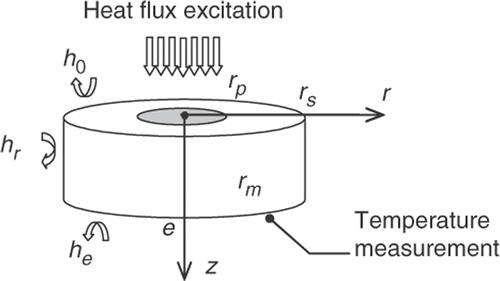
The purpose of this work is to analyse the effect of a plastic deformation of an Aluminium alloy on its thermo-physical properties. It will be demonstrated that the thermo-physical properties change and become anisotropic. These properties are determined by a non-destructive photo-thermal method. In this method Citation5, the central region of the plastically deformed cylindrical sample front face is excited with a lighting source and the temperature rise is recorded on an optimal position (rm) on the rear face. The axial thermal diffusivity (αz), the axial Biot number (Biz) and the radial to axial thermal conductivities ratio (Krz) are then identified, by minimizing the sum of squares of the differences between experimental measurements and numerical results of a 2D model describing the heat transfer in the cylindrical sample. This model is resolved by the finite volume method. Then, the Levenberg–Marquardt method is used for the least squares minimization. This method has the advantage of varying smoothly between the steepest descent and the Gauss methods by nearing the convergence Citation6.
In this article, the experiment is optimally designed in order to choose the optimal heat flux duration, the sample thickness and the thermocouple position. The thermo-physical properties of the deformed sample (in tension) are then identified using an anisotropic 2D model. These results are finally compared with standard measurements (isotropic model) of thermal diffusivities made on both initial and deformed samples.
2. Direct problem
The system under investigation is an anisotropic cylindrical sample with constant heat capacity and density (). This opaque sample is submitted, on a central circular area on its front face, to a constant irradiation flux Q during a small time t0. The radius rp of the considered circular area is smaller than the sample radius rs. The heat losses through lateral and bases areas are represented, respectively, by the coefficients hr, he and h0.
Taking into account the symmetry to the principal axis z, the temperature rise, versus time, at a position (z, r) of the sample is obtained by solving the two-dimensional heat conduction equation in cylindrical coordinates Citation7.
In previous studies, it has been demonstrated that the heat transfer coefficients are correlated and the temperature is not very sensitive to them Citation8. Then, they can be taken to be equal: hr = h0 = he = h.
In this case, the Biot numbers corresponding to the bases areas at z = 0 and at z = e are to be equal to an axial Biot number Biz defined as:
(1)
The radial Biot number Bir can be written as a function of the axial Biot number:
(2)
With Krz the ratio of radial to axial thermal conductivities:
(3)
We consider the following dimensionless variables:
(4)
where is the initial temperature and Tm is a fictitious temperature including the heat flux Q:
(5)
The heat equation is then written, in its dimensionless form, as:
(6)
Subject to the boundary conditions:
(7)
(8)
(9)
(10)
and the initial condition is taken as:
(11)
The heat flux on the base area at z = 0 has a duration t0 and is limited in a surface of a radius rp. Its shape is described in normalized form by:
(12)
The obtainted system of Equations 6a–f is solved numerically by the finite volume method based on the notion of control domain as described by Patankar Citation9. In this article, a regular mesh within the integrated domain has been considered. The radial and axial mesh sizes Δr and Δz are, respectively, taken equal to r/10 and z/10. In order to insure the stability of the numerical solution, we have used an implicit scheme. After descritization, the resulting system of algebraic equations is solved numerically by the iterative line-by-line method.
3. Inverse problem
3.1. Identification method
The inverse problem consists of minimizing the ordinary least squares norm defined as:
(13)
J is optimal if its gradient is zero. That means:
(14)
where X is the sensitivity matrix.
In non-linear estimation problems, the sensitivity matrix X depends on the vector of unknown parameters P. So, the solution of Equation (9) requires an iterative procedure, which is obtained by linearizing the vector of estimated temperatures:
(15)
where Y(Pk) and Xk are evaluated at iteration k. Equation (10) is substituted into Equation (9) and we obtain the following iterative procedure:
(16)
In this iterative procedure, when the problem is ill posed, the matrix XTX is ill conditioned and the computation of its inverse is difficult.
To overcome these problems, a diagonal matrix term μk · Ωk is added to XTX in order to damp oscillations and instabilities due to the ill-conditioned character of the problem. In our case the matrix Ωk contains the diagonal terms of (Xk)TXk Citation10. We obtain then the Levenberg–Marquardt method:
(17)
This method has the advantage of varying smoothly between the steepest descent method, when the damping parameter μk is high, and the Gauss–Newton method by decreasing the value of μk Citation6.
The convergence of the algorithm is achieved using the following stopping criterion:
(18)
with ε = 10−10 and ftol = 10−8 are chosen for all the identifications.
3.2. Confidence interval and confidence region
The Gaussian distributed noise is determined using n measurements of the constant ambiant temperature. The experimental SD of noise is then calculated using the following formula:
(19)
with is the mean temperature.
When the parameters are estimated with 99% confidence level, the exact ones are included in a confidence interval, given by:
(20)
where is the SD for the estimated parameters, defined as:
(21)
where V is the covariance matrix defined as:
(22)
The confidence region is given by Citation11:
(23)
where χnp² is the chi-squared distribution for a given probability of the np estimated parameters.
3.3. Optimal experiment design
The most common criteria for the optimal experiment design are based on the information matrix XTX which summarizes the information content of an experiment Citation11,Citation12. It is necessary to have a great determinant of XTX as a guarantee for great sensitivity coefficients and no correlated parameters. This criterion, also named D-optimality, is used to minimize the volume of the confidence region. However, the ellipsoid can be skinny and long if one parameter has a very large variance compared to the others. So minimizing its volume may mislead the optimal design Citation13.
As one of the main difficulties in inverse heat conduction problems is the behaviour of the information matrix XTX, another approach is to study the condition number (ratio of the largest to the smallest eigenvalue of XTX). The closer this value is to one; the more the problem is well posed. The purpose of this approach, also named modified E-optimality, is to optimize the shape of the confidence region.
It has been previously shown Citation5 that the E-optimality is a compromise between the two approaches (D-optimality and the modified E-optimality). This optimality consists in maximizing the lowest eigenvalue of XTX. In other words, it minimizes the largest parameter variance.
All these criteria give global information about the parameter identification. In most cases the parameter variances criterion Citation14,Citation15 gives more precise information about the identification uncertainty of each parameter. It consists of studying the parameter variances.
4. Experimental device
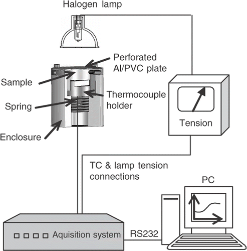
The experimental device is represented in . The sample is heated with a Halogen lamp mounted on an elliptical reflector. The sample receives heat flux only on a central region of the front face. This is realized with help of a perforated PVC plate which covers the sample holder. This cover is coated with a thin Aluminium layer in order to reduce light absorption outside the central region.
The temperature detector consists of a thermocouple placed on the rear face of the sample. The thermocouple/sample contact is granted with help of a spring mounted between the thermocouple holder and the sample (). The detector is related to an acquisition system in order to record the delivered tension.
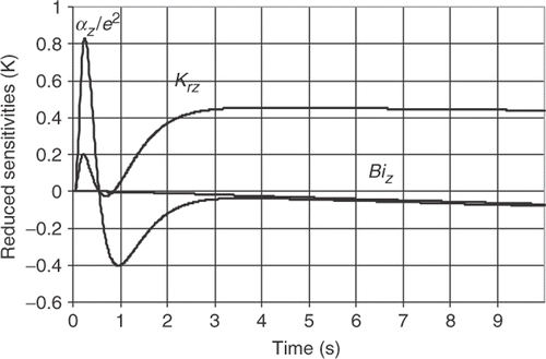
Figure 3. Reduced sensitivity coefficients (αz = 3.1 × 10⁻⁵m2 s−1; Krz = 0.9; Biz = 0.01; rs = 13 mm; e = 9 mm; rp = 2.5 mm; rm = 5 mm; t0 = 10 ms).
The acquisition system receives another signal from the tension generator in order to measure the tension, delivered to the halogen lamp, versus time. This permits the detection of the initial time and heat flux duration.
Using a RS232 connection to a personal computer, the acquisition software permits the representation of the sample rear face temperature and the lamp tension versus time.
5. Results of the optimal design
The calculated temperature is normalized by its maximal value in order to reduce the number of parameters. We first trace the reduced sensitivity coefficients as function of measurement time ().
At short times (1s), the model is more sensitive to α/e2 than to Krz. At long times, the sensitivity of Krz becomes much higher than this of α/e2. Furthermore, we remark that the two sensitivity maxima are reached at different times. Consequently, these parameters are uncorrelated and can be identified simultaneously. Because of its low sensitivity, the Biot number Bi has a negligible influence on the identification.
This qualitative sensitivity analysis is necessary for the experiment design but it cannot be easily used for finding optimal conditions of the experiment. Although, the parameter variances criterium gives more information about the identification uncertainty for a given temperature measurement noise σ.
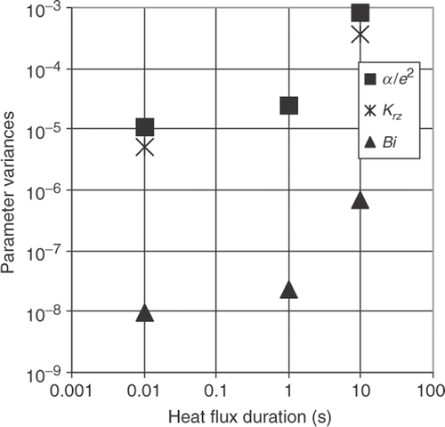
The variances (Vjj) are calculted for each parameter (respectively, V11, V22 and V33 for α/e2, Krz and Bi) and presented in as function of the heat flux duration.
We can remark that, for all parameters, small variations are found for low heat flux durations (), which permit an identification with small uncertainty for all parameters. In this case, the experimental device should have a rapid control of the heat duration.
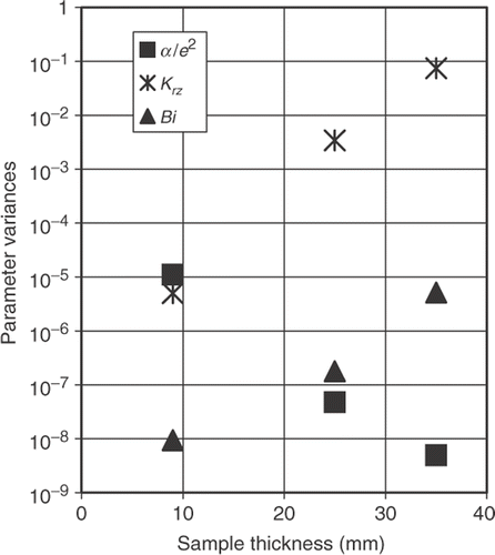
On , we can see that the sample thickness acts in a different way for α/e2 and Krz. Nevertheless, acceptable variance values (involves errors smaller than 2%) for both α/e2 and Krz are given for the smallest sample thickness (e = 9 mm). For greater thicknesses, the variance of α/e2 is low, but the Krz variance becomes very high (>18%).
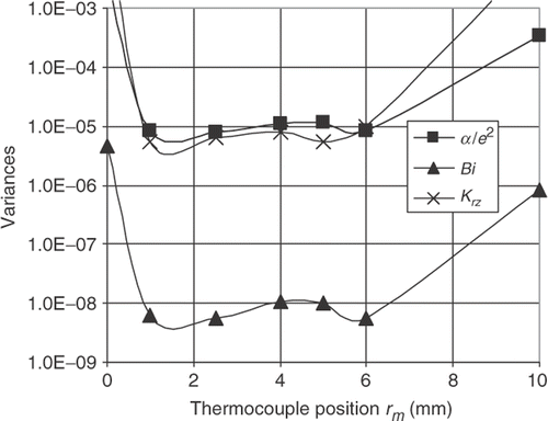
On , we can see that the parameter variances have low values when the thermocouple is placed in the region between rm = 1 mm and rm = 6 mm. Outside this region, the variances become very high.
As a consequence of this optimal experiment design, we should heat a 9 mm thick sample with a radiation source of duration 10 ms and put the thermocouple on the optimal position rm = 3 mm on the sample rear face.
6. Results of the experimental parameter identification
The plastically deformed Aluminum alloy is excited on the central region of the front face (rp = 2.5 mm). The temperature measurements are carried out on the rear face at rm = 3 mm. First, when the sample is heated with a classical flash lamp having a fixed duration of 10 ms and a maximal flux density of 4 J cm−2, the temperature rise was undetectable with our acquisition system. As a solution we have used the heating system described in allowing the light to be concentrated on the central region of the sample (greater heat flux density). Even when the heat duration of this system is 2.3 s, it remains near the optimal region and leads to small parameter variances ().
We have calculated the SD of the measurement noise by recording 100 measurements of the ambient temperature. We have found σ/Tmax = 0.007.
The identification procedure is carried out using the Levenberg–Marquardt algorithm. The temperature is computed by a 2D anisotropic thermal model. All the identified parameters are mentioned with the errors due to the measurement noise (). The identified axial thermal diffusivity is αz = (2.31 ± 0.02) × 10−5 m2 s−1, the Biot number is Biz = 0.0011 ± 0.0004 and the thermal conductivities ratio is Krz = 0.91 ± 0.01. Consequently, the radial thermal diffusivity, which is calculated using Equation (3), is αr = (2.10 ± 0.02) × 10−5m2 s−1.
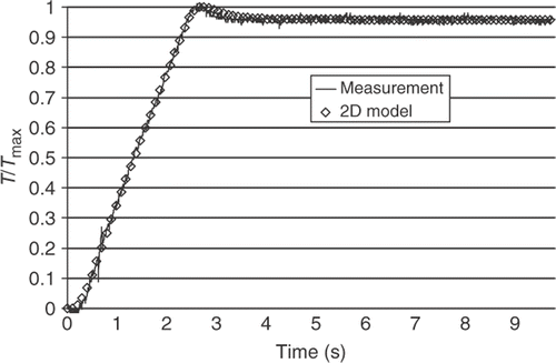
In order to analyse the estimation precision, the measured temperature is plotted on against the theoretical temperature, calculated with the identified parameters. A good agreement is noted.
Figure 7. Temperature measurement vs. 2D model with the estimated thermal parameters of a deformed Aluminum alloy.
In order to verify the last results, we identify the initial isotropic solid thermal diffusivity using a standard flash experiment and an isotropic model considering heat losses. We obtain α = (2.21 ± 0.05) × 10−5 m2 s−1 and Bi = (0.0028 ± 0.0004).
The parameter identification results are summarized on the .
Table 1. Results of the parameter identification.
We can see that the axial thermal diffusivity of the deformed solid (2.31 × 10⁻⁵m2 s−1) has increased in comparison with the initial thermal diffusivity, identified using the isotropic model (2.21 × 10⁻⁵m2 s−1). On the other side, the radial thermal diffusivity, (2.10 × 10⁻⁵m2 s−1) has decreased in comparison with the initial thermal diffusivity.
The thermal diffusivity of the plastically deformed solid is also identified using a standard flash experiment and an isotropic model. We find α = (2.38 ± 0.03) × 10−5m2 s−1 and Bi = 0.0019 ± 0.0002. We remark that the identified diffusivity is a little different from the measured one using the anisotropic 2D model. This can be explained by the fact that the deformed solid is not isotropic and this generates errors on the identification with the standard flash experiment.
7. Conclusion
The effect of plastic deformation of a solid on its thermo-physical properties is analysed. These properties are determined by a non-destructive photo-thermal method. The experiment is optimally designed and an optimal heat flux duration, a sample thickness and a thermocouple position are chosen.
Next an experimental device is mounted. The rear face temperature measurements of a plastically deformed Aluminium alloy are used by the inverse method which is carried out by the Levenberg–Marquardt algorithm and a 2D anisotropic thermal model.
We have seen that the axial thermal diffusivity of the deformed solid in tension has increased (of about 5%) in comparison with the thermal diffusivity of the undeformed solid. The radial thermal diffusivity has decreased by nearly the same percentage. This can be explained by the fact that the solid undergoes traction in the axial direction and a compression in the radial direction.
The thermal diffusivity of the plastically deformed Aluminum alloy is also identified using a standard flash experiment and an isotropic model. We have mentioned that the thermal diffusivity is overestimated in comparison with the measured one using the anisotropic 2D model.
References
- Terada, Y, 2005. Thermal conductivities of platinum alloys at high temperatures, Platinum Metals Rev. 49 (2005), pp. 21–26.
- Wasserbäch, W, Abens, S, and Sahling, S, 2001. Low-temperature thermal conductivity and specific heat of plastically deformed high-purity Tantalum single crystals, J. Low Temp. Phys. 123 (2001), pp. 251–274.
- Pron, H, and Bissieux, C, 2004. 3-D thermal modelling applied to stress-induced anisotropy of thermal conductivity, Int. J. Therm. Sci. 43 (2004), pp. 1161–1169.
- Wang, Y, and Wright, NT, 2005. A relationship between thermal diffusivity and finite deformation in polymers, Int. J. Thermophys. 26 (2005), pp. 1849–1859.
- Mzali, F, Sassi, L, Jemni, A, Ben Nasrallah, S, and Petit, D, 2004. Optimal experiment design for the identification of thermophysical properties of orthotropic solids, Inverse Probl. Eng. Nr. 2, 12 (2004), pp. 193–209.
- Ozisik, MN, and Orlande, HRB, 2000. Inverse Heat Transfer. New York: Taylor & Francis; 2000.
- Ozisik, MN, 1985. Heat Transfer. USA: Wiley–interscience publication; 1985.
- Degiovanni, A, 1977. Diffusivity and flash method, Rev. Gén. Therm. 185 (1977), pp. 417–419.
- Patankar, SV, 1980. Numerical Heat Transfer and Fluid Flow. New York: Hemisphere McGraw-Hill; 1980.
- Press, WH, Flannery, BP, Teukolsky, SA, and Vetterling, WT, 1990. Numerical Recipes in PASCAL. Cambridge: Cambridge University Press; 1990.
- Beck, JV, and Arnold, K, 1977. Parameter Estimation in Engineering and Science. New York: Wiley; 1977.
- Taktak, R, Beck, JV, and Scott, EP, 1993. Optimal experimental design for estimating thermal properties of composite materials, Int. J. Heat Mass Trans. 36 (1993), pp. 2977–2986.
- Emery, AF, and Nenarokomov, AV, 1998. Optimal experiment design, Meas. Sci. Technol. 9 (1998), pp. 864–876.
- Albouchi, F, Fetoui, M, Mzali, F, and Nasrallah, SBen, 2007. Thermal characterisation of poorly conductive solids by the flash method (2007), pp. 633–647, High Temp-High Press 6.
- Albouchi, F, Fetoui, M, Rigollet, F, Sassi, M, and Ben Nasrallah, S, 2005. Optimal design and measurement of the effective thermal conductivity of a powder using a crenel heating excitation, Int. J. Therm. Sci. Nr. 11, 44 (2005), pp. 1090–1097.
