Abstract
An efficient method for material characterization consists in emitting ultrasound waves in a medium, and processing both the emitted and received signals to determine the morphological characteristics of the medium under test, whether static or under low flow [J. Max, Traitement du signal et applications aux mesures physiques, 4th éd., Vol. 1, MASSON, 1985. J. Perdijon, Le Contrôle non destructif par ultrasons, Traité des nouvelles Technologies, série matériaux, (in French) HERMES. A. Ravasoo, and J. Janno, Nondestructive characterization of materials with variable properties, Acta Mechanica, 151 (2001), pp. 217–233. J. SAPRIEL, Techniques de l’Ingénieur (in French) Traité électronique, E1910.]. In this article we present an instrumentation calculation method to determine the phase-shift of ultrasound waves at 40 kHz using a data acquisition card limited to 200 kHz. We describe the experimental platform, then the theoretical development for results exploitation, and two applications using the system: a distance measurement in air medium, and a speed sound measurement in sea water/fresh water mixture.
Nomenclature
| A | = | : Magnitude of emitted signal in volts |
| A0 | = | : Emitted signal name |
| A1 | = | : Received signal name |
| B | = | : Magnitude of received signal in volts |
| fs | = | : Sampling frequency in Hertz |
| t | = | : Time in seconds |
| v | = | : Ultrasound wave speed in meters per second |
| x | = | : Distance travelled by the ultrasound wave in meters |
| ω | = | : Pulsation in rad s−1 |
| ϕ0 | = | : Phase of the A0 signal in radians |
| ϕ1 | = | : Phase of the A1 signal in radians |
| ϕ | = | : Phase-shift between A1 and A0 in radians |
| ϕg | = | : Phase due to the time gap between two measurements in radians |
1. Introduction
Ultrasound waves are mainly used in NDT experiments in medicine, biology Citation1,Citation2, mechanics Citation3, physics and chemistry Citation4–6 to study interfaces and defaults in media.
Material characterization using waves requires the determination of the phase and module of a reflected wave. If the ultrasound signal speed is well-known, as is the case mainly for air medium, the phase of the reflected signal gives the distance covered by the signal, and thus the distance of the reflecting target. In other media in which the distance travelled by the signal can be measured by another method, the phase of the reflected signal allows the determination of the ultrasound wave propagation velocity in the medium Citation7–10.
2. Experimental equipment
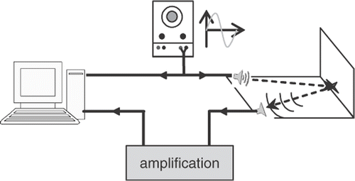
The experimental platform is shown in . The electronic part of the circuit has been presented in CNR’IUT06 Citation11. A generator applies a sinusoidal signal at 40 kHz on the ultrasonic emitter (Murata type MA40B8R) and the signal reflected by the medium under test is detected by the ultrasonic receiver (Murata type MA40B8S). Both are recorded on a computer database via a National Instrument acquisition card, and processed with MATLAB software.
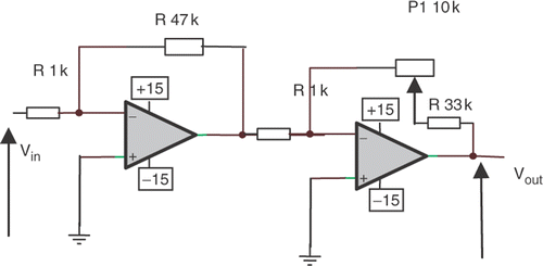
The amplification uses UA741 operational amplifiers, mounted as global non-inverter circuit, composed with two inverter circuits in series to avoid continued electrical component on the output signal. The gain is variable and may be up to 2000. Such a value is used for measurements in air-medium where signal attenuation is very important. The electric scheme is presented in .
The signal processing consists in the determination of the phase-shift between the two signals. The maximum sampling frequency on the available acquisition card was only 200 kHz, and the acquisition using two channels, the maximum sampling frequency available was thus 100 kHz, so we had to find a mathematical treatment allowing an acceptable accuracy of the results.
The sampling frequency chosen must not be a multiple of the signal frequency, to obtain different points from a period to another, in order to describe as precisely as possible the signals during a long acquisition time. The sampling frequency chosen is about 90 kHz, and the acquisition duration 30 ms (1200 periods at 40 kHz).
3. Theoretical development
3.1. Ultrasound wave propagation
The ultrasound wave is defined by the particles forming the propagation medium. For an homogeneous, linear and isotropic medium, the propagation equation is:
(1)
where U represents the magnitude of the displacement, x the travelled distance and v the ultrasound wave velocity.
When we apply an electrical alternative signal A0 to the emitter, composed of a piezoelectrical ceramic, it mechanically oscillates at the same frequency as the electrical signal. Then, the ultrasound wave propagates in the medium and transmits those vibrations to the receiver which is also a piezoelectrical ceramic and creates an electrical signal A1 at the same frequency as the received ultrasound wave. We have to determine the phase-shift between the two electrical signals A0 and A1 in order to determine either the travelled distance x, or the ultrasound propagation speed v.
The mathematical expression of the emitted signal is
(2)
and the received signal is given by the relation
(3)
The additionnal angle ϕg is due to the time gap between two measurements, which cannot be <5 µs, the maximum frequency of the acquisition card being 200 kHz. This gap angle is calculated from the acquisition sampling frequency, fs, chosen by the operator:
(4)
the angle ϕ = ϕ1 − ϕ0 represents the searched phase-shift.
3.2. Phase-shift calculation
By processing the product of the two signals, we obtain
(5)
and, using the following well-known trigonometric relation:
(6)
it becomes
(7)
By taking the average of this expression
(8)
so
(9)
An ambiguity remains about the sign of this angle (ϕ − ϕg). It can be solved by calculating its sine. Thus, if the sign is positive, the angle will be between 0 and 180°, and otherwise, we will have to take the opposite of the angle.
To determine the sine of the (ϕ1 − ϕ0 − ϕg) angle, we will use the trigonometric relation:
(10)
where a represents the (ϕ1 − ϕg) angle, and b represents the ϕ0 angle. Those two angles remain to be calculated.
| - | sin(ϕ1 − ϕg) determination: | ||||
When multiplying A1 (3) by sin(ωt), we obtain:
(11)
then using the trigonometric relation
(12)
it becomes
(13)
By taking the average of this expression, we obtain
(14)
| - | sin(ϕ0) determination: | ||||
By using an analog method, we determine the sine of angle ϕ0:
(15)
then using the trigonometric relation (12)
(16)
by taking the average of this expression, we obtain
(17)
| - | cos(ϕ1 − ϕg) determination: | ||||
We proceed in the same way to determine the cosines of those angles:
When multiplying A1 (2) by , we obtain
(18)
then using the trigonometric relation (6), it comes
(19)
by taking the average of this expression, we obtain
(20)
| - | cos(φ0) determination: | ||||
By using an analog method, we determine the cosine of angle ϕ0:
(21)
then using the trigonometric relation (6)
(22)
by taking the average of this expression, we obtain
(23)
and then we calculate the sine of (ϕ1 − ϕ0 − ϕg) using relation (10).
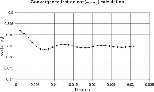
The convergence of the results versus acquisition time has been tested, using Microsoft Excel software with ϕ = 104°, ϕ = 273° and a sampling frequency fs of 94 kHz on each channel and a signal frequency f at 40 kHz, which gives, according to relation (4):
The average values have been recalculated every 100 data to verify the convergence of the calculation.
The cosine target of (ϕ1 − ϕ0 − ϕg) is then 0.885, and the sine target is 0.465.
The results are presented in .
The process converges within an interval of 1\% at the end of a 15 ms acquisition time for cos(ϕ − ϕg).
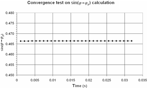
The process converges very quickly for sin (ϕ − ϕg) determination. The results are presented in .
3.3. Experimental data vs. calculated values comparison
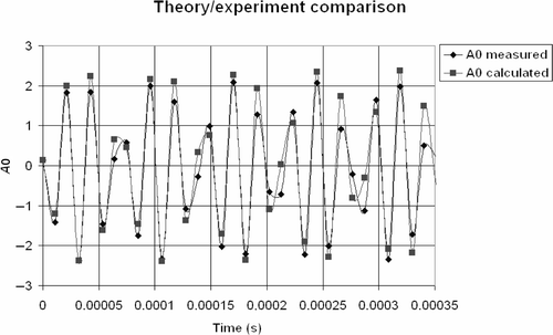
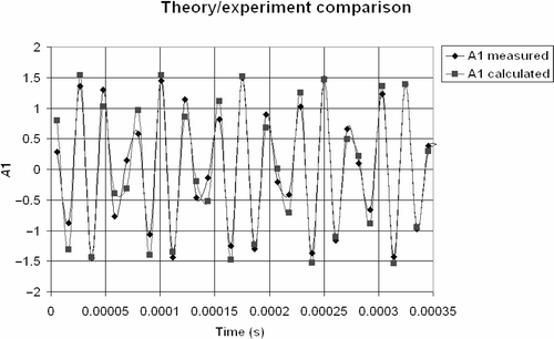
We also compare experimental acquisition data A0 and A1 with values calculated using angle data and relations (2) and (3). The results are presented in and .
Calculated values are close to experimental ones during the beginning of acquisition (14 periods are represented on the graphs in and ).
3.4. Cosine and sine of the phase-shift versus previous values comparison
The results are presented in and .
Figure 7. Convergence study of cos(ϕ − ϕg) calculation for a sampling frequency of 94 kHz from experimental data.
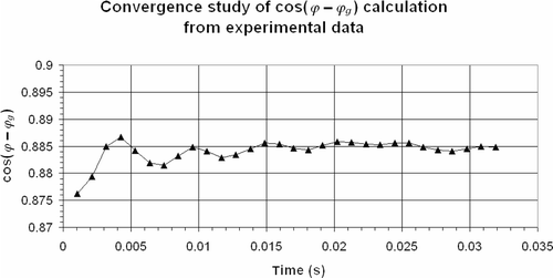
Figure 8. Convergence study of sin(ϕ − ϕg) calculation for a sampling frequency of 94 kHz from experimental data.
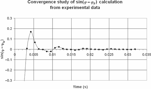
The cosine value converges to the target value of 0.884, but the sine value always converges to 0.
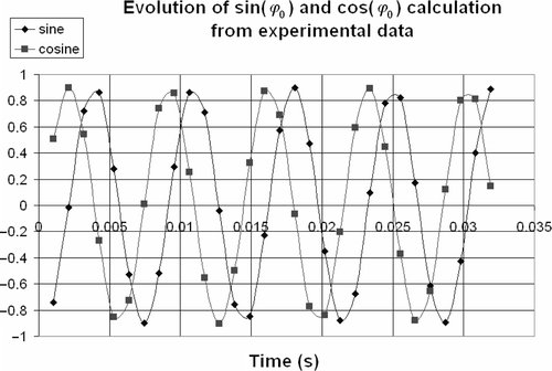
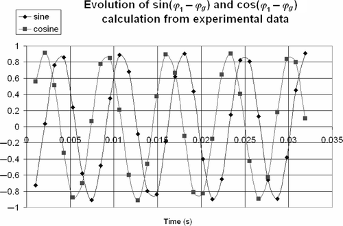
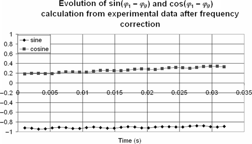
To understand this phenomenon, we have plotted in and the detail of sine and cosine calculated values for ϕ0 and (ϕ1 − ϕg) from experimental data according to relations (14), (17), (21), and (24) every hundred values of A0 and A1, and the results show that ϕ0 and (ϕ1 − ϕg) are not constant during acquisition but time dependent with a period of 7 ms, which correspond to a frequency of 142 Hz. When we average the sine and cosine of those angles for sine determination, the final value vanishes. We notice that this time dependence doesn’t affect the cosine calculation.
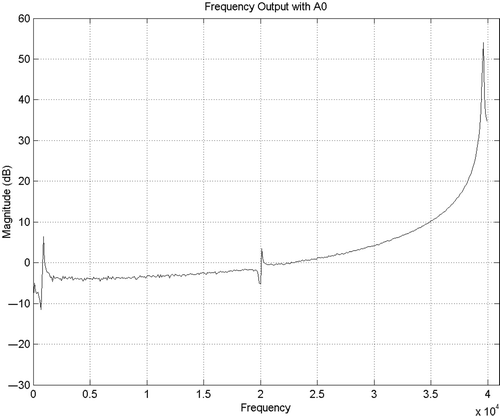
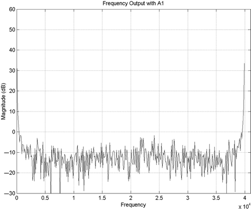
We also plot the fast Fourier transform of signals A0 and A1 using Matlab to analyse different frequency components of the signal. The plots are presented in and .
The A0 signal, directly issued from the generator doesn’t show low frequency components, especially around 100 Hz with sufficient magnitude to explain the oscillation of sine and cosine values of angles (ϕ1 − ϕg) and ϕ0. The A1 signal is relatively noisy but the magnitude remains under 0 dB. Besides, the spectrum shows that the used frequency is not exactly 40 kHz, and the corresponding shift is about 140 Hz. The frequency value is used in all sine and cosine calculations, except in cos (ϕ1 − ϕg − ϕ0), which only uses the product of experimental signals. This explains the previous results with the oscillation frequency of 142 Hz.
So, we extract the effective value of the maximum frequency from the Fourier transformation using Matlab software, and refine its value by a dichotomy method to find which gives non-oscillating results on (ϕ1 − ϕg) and (ϕ0) calculation until the (sin2 + cos2) values become close to one.
In this example, we found f = 39859 Hz. The results of the new sin (ϕ1 − ϕg) and sin(ϕ0) calculation are presented in and .
Figure 13. Evolution of sin(ϕ0) and cos(ϕ0) calculation from experimental data after frequency correction.
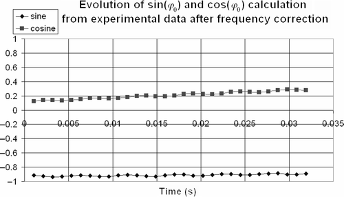
Figure 14. Evolution of sin(φ1 − φg) and cos(φ1 − φg) calculation from experimental data after frequency correction.
Results in the sine calculation convergence are presented in .
Figure 15. Convergence study of sin(ϕ − ϕg) calculation for a sampling frequency of 94 kHz from experimental data after frequency correction.
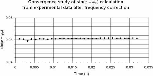
If we consider the results for of (ϕ1 − ϕg) and (ϕ0),we obtain (ϕ1 − ϕg) = (−70.1 ± 4.5)° and (ϕ0 = (−77.8 ± 6.2)°. For this particular case where the two angles are very close, the final result is not very accurate. We have to perform another measurement, if this particular case occurs, because the value of (ϕ0) changes at each experiment.
3.5. Experimental data in water
We have tested the calculation on experimental data in water, with an acquisition duration of 32 ms and a sampling frequency of 98 kHz.
The calculated frequency from Fourier transform is 40.091 kHz, and the results are presented in and
Figure 16. Convergence study of cos(ϕ − ϕg) calculation for a sampling frequency of 98 kHz from experimental data in water.
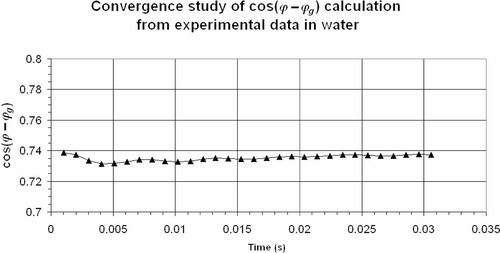
Figure 17. Convergence study of cos(ϕ − ϕg) calculation for a sampling frequency of 94 kHz from experimental data in water.
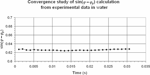
The double determination of the angle from sine and cosine values allows the error estimation on the measured value. The final value of ϕ − ϕg is then between 39 and 43°. The measured value for this example is thus (41 ± 2)°, which is an acceptable accuracy in comparison with the previous experimentation.
We have tested the program with different values of sampling frequencies, the error on the final value remains generally within an interval of 10°. This induces an error of 0.2 mm for distance measurement in air, and 1.0 mm in water when considering the sound velocity in those media.
4. Applications
The typical applications of the phase-shift determination between emitted and received ultrasound signals are either the distance measurement–knowing the velocity of the sound propagation in the medium–or the sound velocity variation measurement for NDC applications.
4.1. Distance measurement
The calculation has been tested with distance measurement in air medium. The target was a metallic wall. The results are presented in .
Table 1. Comparison between experimental and theoretical results.
The value of the air velocity is well known. It is 340 m/s at 15°C and its temperature dependence is given by relation Citation6:
(24)
where θ is the temperature in Celsius degrees.
The distance x between the sensors and the wall is given by the relation
(25)
where α is the angle of signal reflection on the wall and Δt the travelling corresponding time, related to the measured phase-shift by
(26)
The phase rotates very quickly, the ultrasound signal wavelength in the air being 8.5 mm at 20°C. This shows the extreme sensitivity of the experimental system for this application.
4.2. Sound velocity measurement
The contrast of sound velocity in diverse media will then enable the detection of defaults or inclusions in materials or characterize the propagation in the medium.
As a follow-up of a PhD thesis work in our laboratory on the study of a sea water flow at the surface of a reservoir of static fresh water Citation12, we study the relevance of using this ultrasound method.
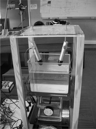
The set-up is presented in . The water-tight sensors are mounted on articulated supports, so they can be oriented one related to the other from different angles and slots in the upper plate allow an XY displacement for future NDC applications. This system conception was the subject of a MASTER I training in our laboratory Citation13.
The container is filled with 2 L of fresh water. We progressively add sea water to it, and measure the sound velocity in this mixture after each addition of 100 mL of sea water.
For measurement analysis, we first consider the sound velocity in fresh water: 1500 m−1 s.
Then we evaluate the number k of entire periods of the signal during its travel. The velocity is given by the relation
(27)
so
(28)
In our experimentation, the frequency is 40 kHz, the sensors are 4 cm apart and the bottom of the container is 4.4 cm below the sensor. So we determine the travelled distance x
and then, during this experiment and according to relation (29), k = 25,
we add the angle k2Π to the measured ϕ value, and calculate the velocity value from
(29)
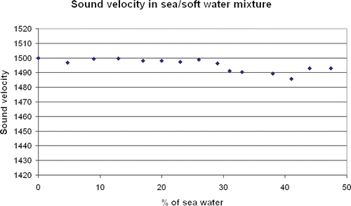
The first results are presented in .
For this application, we choose the solution that is kept with the continuity of the medium behaviour. A threshold in sound velocity in the medium under test would be difficult to determine. This method doesn’t allow detection of the sea water entrance in the container, because the velocity is quite constant at the beginning of the filling; but it could be quite sensitive for higher concentrations.
5. Conclusion
We have presented a new calculation method to determine the phase-shift between emitted and reflected ultrasound signals using cosine and sine determination from basic trigonometric relations. The cosine calculation from experimental data is in line with the simulation, but the convergence of the sine calculation must be tested for each experiment and can be exploited at present with precaution. Fast Fourier transforms are necessary to determine the exact frequency of the experimentation because its value is used for sine and gap angle ϕg calculations.
Nevertheless, distance measurement using a reflecting wall and sound velocity measurements have been performed by the determination of the phase. First results on sea water detection from sound velocity measurement in a fresh/sea water mixture have also been presented. This experiment has to be continued to assess the relevance of this method in such investigations.
References
- Ogasawara, H, Mizutani, K, Ohbuchi, T, and Nakamura, T, 2006. Acoustical experiment of yogurt fermentation process, Ultrasonics 44 (2006), pp. e727–e730.
- Opielinski, KJ, and Gudra, T, 2004. Three-dimensional reconstruction of biological objects’internal structure heterogeneity from the set of ultrasonic tomograms, Ultrasonics 42 (2004), pp. 705–711.
- Jian, X, Guo, N, Abdul, J, and Yeo, HC, 2001. "Characterization of Imperfect Interfaces in IC Packaging using Deconvolved Ultrasonic Signals". In: 10th APCNDT. Brisbane, Australia. 2001, Available at www.ndt.net.
- Ammann, JJ, and Galaz, B, 2003. Sound velocity determination in gel-based emulsions, Ultrasonics 41 (2003), pp. 569–579.
- Kim, KS, Lee, KI, Kim, HY, Yoon, SW, and Hong, SH, 2007. Dependance of particle volume fraction on sound velocity and attenuation of EPDM composites, Ultrasonics 46 (2007), pp. 177–183.
- Maebayashi, M, Endo, M, Matsuoka, T, Koda, S, and Isono, Y, 2006. Acoustic analysis of bound rubber formed in silica/SBR compounds, Ultrasonics 44 (2006), pp. e1101–e1104.
- Max, J, 1985. Traitement du signal et applications aux mesures physiques, . Vol. 1. MASSON; 1985.
- Perdijon, J, Le Contrôle non destructif par ultrasons, Traité des nouvelles Technologies, série matériaux, (in French) HERMES.
- Ravasoo, A, and Janno, J, 2001. Nondestructive characterization of materials with variable properties, Acta Mechanica 151 (2001), pp. 217–233.
- SAPRIEL, J, Techniques de l’Ingénieur (in French). Traité électronique; p. E1910.
- Breton, S, Rochard, S, Jaouen, C, and Abouna, M, p. 6, Conception et réalisation d’un circuit d’émission ultrasonore autonome et souple d’utilisation session EP2, CNR’IUT06, Brest, 1–2 juin 2006, (in French) Available at www.cnriut.fr.
- Dorville, JF, 2006. Etude d’un écoulement gravitaire à la surface d’un bassin au repos. 2006, Thèse de Doctorat de l’Université de Bretagne Occidentale–Brest–France.
- Coadic, RLe, 2006. Utilisation de l’acoustique ultrasonore pour la caractérisation des matériaux (2006), stage Master I PCI UBO- LIME IUT–Brest, avril–juin.
