Abstract
Identification of thermal resistance of the gas-gap between the ingot and mould, as well as the heat flux distribution on the phase change from the solid side during continuous casting of metals is the subject of this article. Analysed parameter estimation problems of the steady-state heat conduction belong to the group of inverse problems. The presented work shows the possibility of applying the least square adjustment method with a priori data for the identification of thermal resistance, the interphase location as well the heat flux distribution on the phase change from the solid side and the temperature field within the ingot and mould. The most important feature of the approach is that the unknown thermal resistance of the gas-gap is obtained from the temperature measurements at a number of sensors located in the wall of the mould, and some sensors located in the ingot, by solving the appropriate inverse problem. The validity of the solution of the inverse problem is checked by comparison with the results of direct problem. In this work, a front-tracking method with an automatic mesh generation finite element technique (so called deforming or moving finite-elements) for steady-state equation conduction-advection problems is developed. Such an approach makes it possible to find the exact solid-liquid interface location, because it is the integral part of the solution. Due to the strong convective nature of the problem (casting velocity, thermal parameters) the special up-wind technique is applied.
1. Introduction
One of the most important technological parameters which influences the process of solidification of the metal in the ingot is thermal resistance of the gap between the mould and ingot. The inverse technique is proposed by the authors for the identification of thermal resistance as well the heat flux distribution on the phase change from the solid side on the base of temperature measurements within the wall of the mould. The process of continuous casting is analysed.
A number of theoretical models and experiments have been evaluated to describe thermal resistance in the processes of continuous casting Citation1,Citation2. Those models should, however, deal with a very complex phenomenon taking place within the ingot. We can mention here phase change, solidification shrinkage, thermal contraction etc. It makes the problem very difficult to describe and solve. Experiments, for example measurements of temperature in the cast and in the mould, cannot be directly used to describe thermal resistance but can be used for validation of the mathematical models.
Thermal resistance between the cast and mould can be identified using the inverse technique. Presented work shows the possibility of applying of the least squares adjustment method within a priori data for identification of thermal resistance. To apply the method the mathematical model of the process has to be evaluated. Mathematical models of the physical processes usually involve several input data, which directly or indirectly come from the measurements. In the situation when mathematical models of the process are evaluated and also certain quantities, which appear in the model, are known a surplus of information arises. That surplus of information can be used for evaluating the most likelihood values of unknown quantities and measurements. This is due to the fact that either the mathematical model or measurements are not absolutely exact. Inaccuracies of the mathematical models usually result from the incomplete knowledge about the process. Very often mathematical difficulties force the simplification of the model. Inaccuracies of measurement generally result from the accuracy of measurement. A surplus of information gives the opportunity to improve accuracy of unknown quantities and parameters compared to the situation when a minimum number of information concerning the analysed process is available. The problem of calculating the most likelihood estimates of the sort for quantities (in the sense of given criterion) is often called the co-ordination technique. The most effective and widely used co-ordination technique is the least square adjustment method (LSAM) which belongs to the group statistically optimal estimation methods. The least square adjustment technique refers to two groups of quantities: unknown (which are not measured) and measured. These quantities are interrelated by the equations of the mathematical model (so called constraint equations). Contrary to the classical algebraic problems, all the quantities are treated here as stochastic. An essential aim of calculations is to evaluate the most likelihood estimates of unknown and measured quantities.
In this article, the problem of the identification of thermal resistance between the mould and ingot is solved using the least squares approach with a priori data.
2. Formulation of the problem
The first stage in formulating the boundary problem is to evaluate the mathematical model of the transient temperature field within the ingot and mould.
The finite element model was adopted for solving the analysed Stefan problem under the following assumptions:
| 1. | the cylindrical geometry of the calculation domain (ingot and mould) is considered, | ||||
| 2. | the problem is steady state in the co-ordinate system attached to the mould, | ||||
| 3. | the temperature distribution in the ingot and mould are axially symmetrical, | ||||
| 4. | the phase change occurs at a constant temperature, | ||||
| 5. | the velocity of the ingot is constant, | ||||
| 6. | the material parameters, like thermal conductivity or heat capacity are temperature independent, | ||||
| 7. | the heat is transferred through the gap between the ingot and mould. | ||||
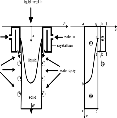
Metal is moving at the constant velocity wz through a region Ω. The region Ω is defined as a control volume, where Ω = ΩL ∩ ΩS and ΩL ∪ ΩS = 0. Where ΩL–liquid domain, ΩS–solid domain, ΩC–mould domain, ΩG–gas-gap between the mould and ingot.
The solidification of metal takes place within the region Ω. The governing equation in the Eulerian frame (the co-ordinate system is attached to the mould) without heat sources has a form Citation3,Citation4:
(1)
where: wzS = wz ∧ wzC = wzG = 0, r–radial co–ordinate, z–axial co-ordinate, T(r, z)–is a temperature at spatial point (r, z), ρi–density, cpi–specific heat, λi–heat conductivity, i = S or C indicates the solid phase or a mould, respectively, wz–is the casting velocity. The temperature of the solid/liquid interface, is known:
(2)
where Tm is the solidification temperature and Ωbf indicates the solid/liquid interface.
The set of the most important external boundary have a form:
where: Tk–specified final temperature of the solidified (and cooled) metal, T∞–ambient temperature, α1–heat transfer coefficient,
–is a unitary vector. Indexes S and C refers to the solid phase and mould domain, respectively.
3. Finite element formulation
To solve the boundary Stefan problem, the finite element approach has been used. Using the Galerkin method Citation5,Citation6 we obtain the algebraic system of linear equations of the following form
(3)
where A is stiffness matrix, T is a one-column matrix of unknown temperatures, and Q is a one-column matrix of boundary conditions.
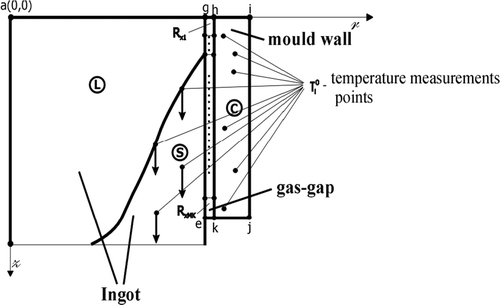
To determine the solid/liquid interface position as well as the heat flux from the solid side on the interface, it is necesary to have additional information to solve the direct problem. This information is added to the problem formulation as temperature measurment points (, i-number of measurement points in the ingot) located in the ingot or mould (). The location of these points have a significiant influence on the calculation time and accuracy. To verify the solid/liquid interface position, we assume that the heat flux from the solid side plays a significiant part in the solidification process. So the update of the solid/liquid interface can be done based on the assumption that:
(4)
where χ–is the latent heat of fusion,
–is the velocity vector of the solid/liquid interface in the Lagrangian frame,
–is a unitary vector. After integrating over an element boundary and without losing the generality, we will take into consideration only the boundary over a single element:
(5)
or
(6)
where
(7)
Using the Galerkin method with quadratic shape function, we can calculate the heat fluxes on the interphase elements. After transformations of the integrals (5) we obtain:
(8)
where A1, A2, B1, B2 are the coefficients. The left side of Equation (6) we can define as:
(9)
During calculation the difference between the calculated and measured temperatures has to satisfy (with respect to given accuracy ε) the following inequality:
(10)
The iteration procedure starts from the arbitrary position of the solid/liquid interface defined by the user. Then we obtain the temperature field by solving the linear system of algebraic equations obtained from (1) using the Galerkin method with the isothermal boundary condition on the solid/liquid interface. To check if the position of the interphase is in the right place, we search the discrepancy (10) for each finite element where measurement points are located. When the condition (10) is not fulfilled then we have to update the interface position. When Δqe > 0 then we move the interface location in the positive direction, otherwise in negative direction.
To update the position of the interphase we assume that the temperature distribution close to the interphase location can be interpolate by a priori given function TeS(z) e.g. polynomial of the shape:
(11)
which cross the points (
), i = a, b, c. The heat flux in the solid phase is equal to
(12)
Hence, the inequality of the heat flux on the boundary interphase will be expressed as follows:
(13)
where dEe is the interface update on each element from the boundary interface. The value of dEe is calculated from relationship:
(14)
where
(15)
The next difficulty to overcome is the convective nature of the analysed problem. When applying the standard Galerkin method, the matrix associated with the convective term is strongly non-symmetric, and we can obtain non-realistic results of calculations. In practice, solutions are often corrupted by spurious node-to-node oscillations. Oscillations are more likely to appear in convection-dominated cases (high Peclet numbers) when a downstream boundary conditions forces rapid change in the solution. It is known that for a Peclet number >1:
(16)
the solution has strong oscillations. The remedy for this problem is to refine the mesh in such a way that the element Peclet number is <1. In a finite element framework, up-winded convective terms can be developed in several different ways. The initial upwind finite element formulation employs modified weighting functions to achieve the upwind effect. In essence, the element upstream of a node is weighted more heavily than the convective downstream of a node. We use the method proposed in Citation7, based on modification of the weighting function. In the case when only movement of the ingot is considered in the axial direction z with the constant velocity wz, we select the upwind parameters as follows:
(17)
4. Algorithm of the least squares adjustment
Numerous physical problems (including numerical representation of boundary problems of heat conduction) can be described in the form of linear matrix constraint equation:
(18)
where A are rectangular matrices of coefficients (corresponding to the Equation (3)), x = [T, λ] denotes vector of nodal temperatures T (few of them are known from measurements) and unknown thermal conductivity of the gap λ, c is the vector of boundary conditions.
The solution of Equation (18) can be derived by applying the least square approach. Equation (18) is satisfied by the exact values of quantities x. When we put results of x0 measurements and initially estimated values of unknowns into Equation (18), we get
(19)
where w denotes the vector of discrepancies. The aim of the least square adjustment technique is to find such corrections
which satisfy constraint equation:
(20)
and minimize quadratic form
(21)
where V is the covariance matrix of the results of measurements.
As the result of the solution of an optimization problem (21) and (20) one obtains the following relationship describing estimates of unknown quantities and covariance matrix of
?:
(22)
(23)
where F = AVAT.
Relationships (22) and (23) are widely used for the co-ordination of a wide range of problems, including the thermal processes and inverse heat conduction problems Citation8. On the other hand, the standard least squares adjustment technique often leads to the wrong results when solving inverse boundary heat conduction problems Citation8. Accuracy of estimation can be improved by the modification of optimization procedure by adding a stabilizing term. This concept is realized by the least squares adjustment method with a priori data.
When analysing physical or technical problems it is usually possible to estimate values for unknown quantities λ0 and covariance matrix Gλ0 of initial estimate of unknown quantities. This a priori information lies at the base of the formulation of the enhanced least squares method. This concept has been successfully used to stabilize the solution of inverse boundary heat conduction problems Citation9,11].
Basic matrix equations describing a problem (constraint equation) have a form (18) and include unknown quantities λ and results of measurement T. Similar to the standard least squares approach we have to find such corrections which satisfy constraint Equation (20) and minimize certain quadratic forms. In the case of the proposed approach, that quadratic form involves either unknown or measured quantities:
(24)
where V is the covariance matrix of measurements and Gλ0 is the covariance matrix of initially estimated unknowns λ0.
For LSAM with a priori data matrix decrease the sensitivity of the algorithm on inaccuracies of input data and improve the accuracy of the method.
5. Identification of thermal resistance between the cast and mould
Presented method was used for identification of thermal resistance between copper ingot and steel mould. Thermal resistance in the gap between the ingot and mould is strongly dependent from the heat conductivity in the gas-gap. This relation can be expressed in the form:
(25)
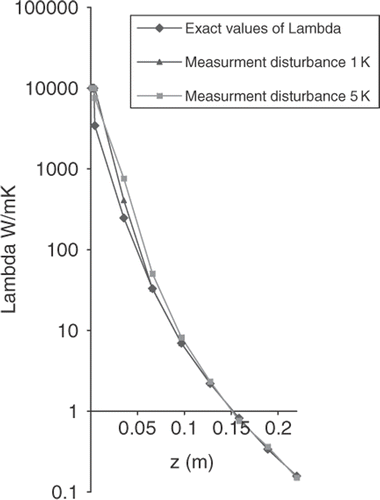
where λi–heat conductivity, HG–thickness of the gas-gap, Ri–thermal resistance of the gas-gap. Since the thickness of the gas-gap HG is assumed at the mathematical model to be constant, then in the identification analysis will be considered the virtual heat conduction coefficient λi on the place of thermal resistance Ri calculated from (25).
An ingot has 1 m length and 0.1 m of radius. The mould (made from steel) has a length 0.22 m and its wall is of 0.025 m thickness. Thermo-physical properties of metal are: thermal conductivity λS = 394 W m−1 K−1, specific heat cS = 380 J kg−1 K−1, density ρS = 8930 kg m−3, the temperature of phase change Tm = 1083°C and the velocity of the ingot wz = 0.002 m s−1. Due to the axial symmetry, only half of the domain is discretized. Along the surface cd, first kind boundary conditions were assumed, i.e. Tk = 20°C. On the surface ed, ek, kj, ij boundary condition of the third kind is assumed, where α1 = 9000 W m−2 K−1, α2 = 1500 W m−2 K−1 and T∞ = 20°C. Relative accuracy for convergence of calculations calculation is selected as 0.1%. The values of temperature measurements for identification of thermal resistance of the gas-gap were selected from the solution of the direct problem. The size of the gas-gap in the direct problem was calculated on the analysis of the simplified analysis of thermal shrinkage of the solidified part of the ingot.
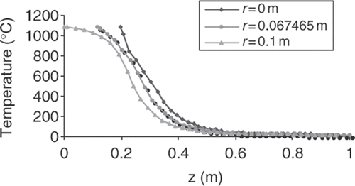
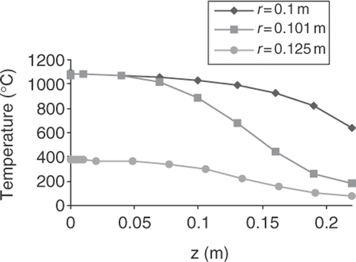
Sample temperature distribution in the ingot and mould is shown in Figures and .
On the basis that the sensitive coefficient analysis it was observed that the major influence on the identified values have the temperature measurements in the mould. Measurement points were located at the nodes of the finite element mesh in mould for inverse problem and for direct problem along the axis of symmetry of the ingot (cb boundary).
In this article the measurement results were simulated on the basis of the solution of direct problem (‘exact’ solution) corresponding to the inverse problem. Inaccuracy of measurements was simulated by adding the random disturbance to the exact solution:
(26)
where:
–simulated measurement result, Ti–exact value (in the sense of the solution of the direct problem), δ–maximal measurement disturbance, ξ–random number form the range [0,1].
To check the influences of measurement error on the accuracy of identification, the following maximal measurement discrepancy were chosen: δ = 1 K and δ = 5 K.
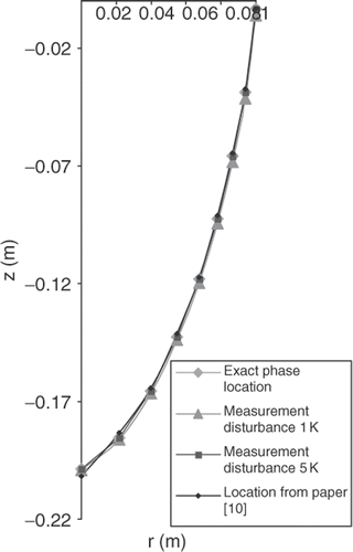
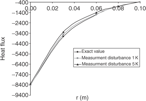
The results of the identification are shown in , and absolute error of identification is given in . It can be seen that differences between exact and identified values are relatively low and appears just at the beginning of the gas-gap. The interface location is presented in . It is easy to see that for the analysed measurement discrepancy δ the difference between exact solution and results of identification is not observed.
Table 1. Results of identification.
6. Conclusions
The inverse problem was formulated and the algorithm of the least square adjustment method with a priori data was used for identification of thermal resistance and heat fluxes between ingot and mould during continous casting of metals. Calculation and numerical tests have proved that proposed method can be effectively used for solving the inverse boundary heat conduction Stefan problem. Important in the future of the least squares adjustment method is the possibility of direct statistical estimation of results. It is an important advantage because in practice there is usually no possibility of verifying the accuracy of the calculations. The result of the present inverse analysis can be used for optimization of the process of casting metals.
Acknowledgements
The financial assistance of the National Committee for Fundamental Research, Poland, within the grant O R00 0022 06 and O R00 0021 06 is gratefully acknowledged herewith.
References
- Schmidt, P, 1994. "Heat transfer in permanent mould casting". In: Proceedings of the COST 504 Conference Advanced Casting and Solidification Technology. III Report. Aachen, Germany. 1994.
- Prinz, B, 1994. Measuring and modelling of the influence of coatings on the heat transfer between melt/casting and mould during the permanent mould casting of aluminium alloys. COST 504/III Report. Germany: Aachen; 1994.
- Carslaw, HJ, and Jäger, JC, 1959. Conduction of Heat in Solids. Oxford: Oxford University Press; 1959.
- Özisik, MN, 1980. Heat Conduction. New York: Wiley; 1980.
- Kikuchi, N, 1987. Finite Element Methods in Mechanics. Cambridge: Cambridge University Press; 1987.
- Reddy, JN, 1993. An Introduction to The Finite Element Method. USA: McGraw-Hill; 1993.
- Heinrich, JC, and Zienkiewicz, OC, 1977. Quadratic finite element schemes for two-dimensional convective–transport problems, Comp. Meth. Appl. Mechanics Eng. 11 (1977), pp. 1831–1844.
- Szargut, J, 1984. The least square adjustment technique in thermal engineering (in Polish). Wrocław: PAN; 1984.
- Skorek, J, 1983. Applying stochastic method for solving inverse heat conduction problems (in polish). Presented at Proceedings of the Symposium on Eat and Mass transfer.
- Nawrat, A, and Skorek, J, 2002. Determination of the temperature field in the process of continuous casting of metals by front tracking method, Bull. Polish Acad. Sc., Arch. Thermodyn. 23 (2002), pp. s.21–s.41.
- Szargut, J, and Skorek, J, 1991. Influence of the preliminary estimation of unknowns on the results of co-ordination of substances and energy balances, Bull. Pol. Acad. Sci. Thermodyn. 39 (1991), p. 335.
