Abstract
An inverse shape design method for turbomachinery blades based on a time-accurate solution of the viscous flow equations is presented. The design scheme is formulated such that either the blade pressure distributions on pressure and suction surfaces, or the blade pressure loading and its thickness distribution can be prescribed as design variables. The blade profile is modified using a virtual velocity distribution that would make the momentum flux on the blade surfaces equal to the design momentum flux. The flow is simulated by solving the Reynolds-averaged Navier–Stokes equations that are discretized using a cell vertex finite-volume method, where an arbitrary Lagrangian–Eulerian formulation is used to account for mesh movement. An algebraic Baldwin–Lomax model is used for turbulence closure. The inverse method is first validated for a transonic compressor cascade; it is then used to redesign a subsonic turbine and a transonic compressor. The results show that the design method is rather robust, flexible and useful in reshaping the blade geometry to achieve the prescribed design variables. They also indicate that by carefully tailoring the design target, significant improvement can be achieved in the blade aerodynamic performance.
Nomenclature
| A – | = | Speed of sound |
| c – | = | Axial chord length |
| CL – | = | Load coefficient |
| F – | = | Convective flux vector |
| f – | = | Blade camber line, f(x) in Equation (9) |
| k – | = | Constant, Equation (6) |
| M – | = | Mach number |
| = | Reduced mass flow rate | |
| n – | = | Unit vector normal to the wall |
| p – | = | Pressure |
| Re – | = | Reynolds number |
| u,v – | = | Cartesian velocity components |
| δs – | = | Wall displacement in normal direction |
| δt – | = | Time interval |
| s/c – | = | Cascade solidity |
| α – | = | Flow angle |
| ρ – | = | Density |
| ζ – | = | Loss coefficient |
| Γ – | = | Stagger angle |
| ω – | = | Relaxation factor, Equation (5) |
| ωs – | = | Smoothing coefficient, Equation (11) |
Subscripts
| 1, 2 – | = | Inlet, exit |
| d – | = | Design |
| is – | = | Isentropic |
| n – | = | Normal |
| v – | = | Virtual |
| s – | = | Smoothing |
Superscripts
| ± – | = | Blade pressure and suction sides |
| d – | = | Design |
| v – | = | Virtual |
1. Introduction
In situations where the required blade aerodynamic performance is known in some detail, e.g. the blade pressure loading or the pressure distribution on the blade surfaces, inverse methods are probably the best and most efficient approach to design. The computational time taken by inverse methods is comparable with that taken by analysis methods, which makes them less time consuming than almost all optimization methods and offers them as an attractive tool when designing turbomachinery blades for a target performance.
In the inverse shape design problem, the flow governing equations are recast such that the required detailed performance is prescribed, and the corresponding blade shape and the flow field are obtained simultaneously as part of the inverse design solution. The implementation of these methods requires modifications of the computational fluid dynamics (CFD) flow solver and/or boundary conditions. Two-dimensional inverse blade design methods typically assume a target pressure distribution Citation1–7, Mach number Citation8 or velocity distribution Citation9 along the blade surfaces. Other inverse methods assume a target distribution of the blade pressure loading and its thickness distribution Citation10–13. Starting from an initial guess for the blade shape, these methods use a flow simulation tool to compute the flow field, then the difference between the calculated and the target, e.g. pressure distribution on the blade surfaces is used to change the blade shape and the process is repeated until convergence, i.e. until the target, e.g. pressure distribution is asymptotically reached.
Almost all inverse design methods solve the problem as a time-marching (quasi-steady) problem and do not account for the blade movement in the problem formulation. The errors resulting from the quasi-steady assumption will propagate into the new blade shape which will affect the pressure field computed at the next iteration. In some design approaches and for some target pressure distributions, such errors can result in an inaccurate blade shape or in the divergence of the iterative process. A possible example of this situation is the work of Yang and Ntone Citation5, which extends the work of Thompkins and Tong Citation3,Citation4 to viscous flow where the method failed to achieve the target pressure distribution for a subsonic cascade redesign. Moreover, that approach was not successful in designing transonic blades. The elimination of the transient errors by using a time accurate formulation will result in a more robust method that can handle relatively ‘difficult’ design cases. This fact is verified in part by Demeulenaere et al. Citation6 who used a time marching (but not time accurate) approach where the mesh movement was accounted for in the formulation, thus improving the convergence of the inverse method.
The inverse blade design methods for viscous flows were shown to be quite efficient Citation2,Citation6,Citation7,Citation11 however, they still carry some traces of inviscid flow implementation. Some methods Citation2 involve viscous–inviscid interaction (so that the metal profile has to be obtained by subtracting the displacement thickness), some Citation11,Citation13 use the flow tangency condition to find the new blade camber line, while other methods Citation6,Citation7 use the transpiration approach where a velocity tangent to the blade is needed. In all the preceding methods, it is assumed that the flow is attached and the boundary layers are well behaved, so that the velocity at the edge of the boundary layer can be used to get the new blade profile.
Recently, Daneshkhah and Ghaly Citation14 have developed an inverse design method that is fully consistent with viscous flow, where the pressure distributions on the blade suction and pressure surfaces are chosen as the design variables. The blade shape is modified based on a virtual wall motion originally presented by Thompkins and Tong Citation3,Citation4. This wall velocity is determined from the difference in momentum fluxes between the present and the target pressure distributions. The inverse problem is simulated using a time accurate scheme on a moving and deforming mesh. They Citation14 have successfully verified it and applied it to the redesign of different transonic and subsonic turbine and compressor cascades.
In this article, the previous work Citation14 is modified so that the blade loading and its thickness distribution can also be chosen as design quantities. The blade loading allows for a better control of the blade aerodynamic performance and the blade thickness distribution guarantees that the blade shape is closed and provides more control over the blades structural and manufacturing constraints. The design method formulation and implementation follows rather closely the previous work Citation14. The new formulation is validated on an existing transonic compressor cascade, and is applied to the redesign of a subsonic turbine and a transonic compressor to obtain a target loading and thickness distributions. The effect of using a time accurate formulation on robustness, accuracy and consistency is emphasized and the approach used to prescribe the blade loading that would improve or eliminate undesirable flow features, hence improving the blade performance, is discussed in some detail.
2. Flow analysis method
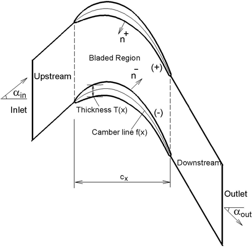
The governing equations for the unsteady, viscous flow in a domain with moving boundaries are the Reynolds-averaged Navier–Stokes (RANS) equations which are expressed in an arbitrary Lagrangian–Eulerian (ALE) formulation. The grid velocities for a moving and deforming computational domain are computed from the space conservation law (SCL) Citation15. The spatial discretization is performed using a cell-vertex finite-volume method of Jameson's type on a fully unstructured triangular mesh Citation16. A time accurate solution is ensured during the design process using a dual time stepping scheme Citation17. The method uses an explicit Runge–Kutta time-stepping procedure to obtain the steady state solution, where local time-stepping and implicit residual smoothing are employed for convergence acceleration. The inflow and outflow boundary conditions are based on a linearized one-dimensional characteristic method Citation18. The Baldwin–Lomax model Citation19, adapted for the use on unstructured meshes Citation20 is used for turbulence closure. shows the computational domain and the cascade notation.
3. Inverse design formulation
The current approach to inverse design is to replace the fixed-wall boundary condition with a moving-wall boundary condition; this movement is controlled by a virtual velocity distribution Citation3,Citation4. The transient momentum flux on the blade surfaces assuming a virtual velocity distribution has the following form:
(1)
where vv = (uv, vv) is the virtual velocity vector and n = (nx, ny) is the surface normal vector. At design condition the virtual velocity distribution vanishes and the only contribution to steady state momentum fluxes are through the target (design) pressure pd, that is:
(2)
The virtual velocity can be calculated by requiring that:
(3)
which can be solved directly to obtain the virtual velocity components:
(4)
It follows that the wall displacement δs in a time interval δt is equal to:
(5)
where
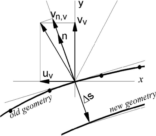
is the virtual velocity component normal to the blade surface and ω is introduced as a relaxation factor for the global stability of the scheme. The negative sign in Equation (5) indicates that the wall moves in a direction opposite to
. shows a schematic representation of the wall movement.
A stability analysis of the scheme shows that the virtual velocity distribution must be heavily relaxed to ensure convergence of the scheme to a steady state solution Citation4. The relaxation factor is found to have the following form:
(6)
where a is the speed of sound and k is a constant, which is typically 0.2 for subsonic flow and 0.05 for transonic flow design cases.
In order to prescribe a loading distribution, Δpd, as the design input, the surface pressure distributions that would satisfy that loading need to be computed, since the numerical implementation requires these pressures to compute the virtual wall velocity. The target pressure distributions can be computed from the prescribed loading distribution as:
(7)
where the ± sign refers to the blade pressure and suction surfaces. In some cases, Equation (7) may result in
> 1 which is a non-physical value (since pressure is non-dimensionalized by the inlet total pressure). Given that the pressure distribution on the pressure side is usually less sensitive to changes in geometry, for such cases,
is taken to be that prevailing from the current iteration, so that:
(8)
Note that p+ will change with the iterations as the tangential thickness is fixed.
To satisfy the imposed blade thickness, the new blade shape is generated as follows. The camber line is displaced by the average change in blade shape on both blade surfaces obtained from Equation (5). The imposed blade thickness is then added onto this new camber line, hence generating the blade pressure and suction side profiles.
(9)
(10)
To ensure a smooth blade profile, the blade camber line f(x)new has been smoothed before generating the blade profiles, , in the following way:
(11)
where j refers to discrete points on the blade camber line. A typical value for the smoothing coefficient is ωs = 0.2. This smoothing eliminates small geometry oscillations that can slow down the global convergence. However, the correct blade camber line for an arbitrary prescribed loading may not be genuinely smooth and the application of Equation (5) may introduce a real position error. Therefore, a careful balance must be maintained between smoothing out the profile and producing the specified pressure distribution. shows the cascade notation used throughout this work.
4. Inverse design algorithm
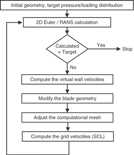
The above design technique is implemented into the unsteady RANS equations where the blade movement is the source of unsteadiness. After each blade shape modification, a time-accurate solution is obtained for the flow field on the moving and deforming geometry. Hence temporal errors associated with the blade movement are eliminated, which makes this approach more robust than current inverse methods that use a quasi-steady approach. shows the inverse design iterative process. Starting from a semi-converged solution on an initial geometry and a target pressure distribution, a virtual velocity distribution is computed from Equation (4) on the blade surfaces from which the local geometry modifications are deduced. After the geometry modifications, the computational mesh is adjusted using transfinite interpolation. The grid displacements and velocities are then computed for the entire computational domain using SCL Citation15. The unsteady governing equations are marched in pseudo-time until the local problem converges and the transient pressure distribution on the modified geometry is obtained. The process is repeated until the L2 norm of the grid velocities is decreased to the desired tolerance, which ensures that a steady state condition is asymptotically reached and the target pressure distribution is achieved on the latest blade profile. Note that the flow unsteadiness is a result of the blade virtual velocity, which vanishes as the target, e.g. pressure distribution on the blade surfaces is asymptotically reached. In other words, the target blade shape corresponds to a steady state blade loading or pressure distribution on the blade surfaces, which usually corresponds to the design point.
The overall computational time for an inverse calculation depends on the number of geometry modifications and the computing time required for obtaining the time accurate solution after each geometry modification.
5. Results
In this section, the inverse design method is assessed for its robustness and accuracy by inverse designing an existing transonic compressor blade using its original loading distribution as design target but starting from a different blade geometry. The inverse method is then applied to redesign a subsonic turbine blade profile and a transonic compressor in order to achieve a target loading distribution.
5.1. ONERA transonic compressor cascade
A highly loaded transonic compressor cascade that was experimentally investigated at ONERA Citation21 is chosen for the inverse design assessment. The cascade geometrical characteristics and flow data are presented in . shows the Mach contours resulting from the flow analysis. There is a local transonic region that ends with a normal shock at about 20% chord followed by a small separation bubble.
Table 1. ONERA cascade data and flow conditions.
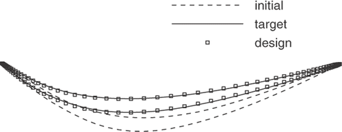
The viscous inverse design method is assessed by inversely designing the original blade shape (referred to as target geometry). The blade thickness distribution and its pressure loading which is obtained by a flow analysis are prescribed as the design input. The starting geometry has the same tangential thickness distribution but a camber line distribution different from the target one ().
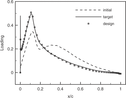
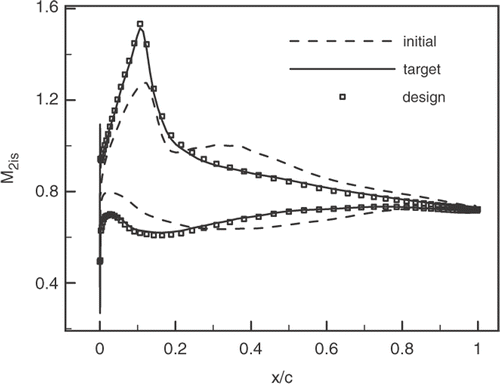
The resulting blade loading and isentropic Mach number distributions for the initial, target and inversely calculated cases are depicted in and . These figures show clearly that the inverse method has achieved, rather accurately, the target pressure loading and the corresponding pressure distribution on the blade surfaces.
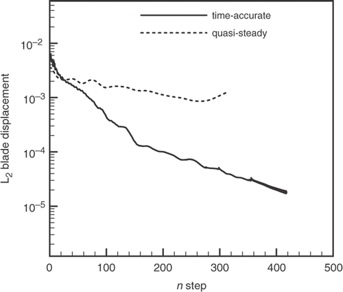
In order to demonstrate the benefits of using a time-accurate simulation on a moving mesh and to describe the evolution of the blade shape from the initial guess to the final steady shape, the design approach was carried out using the time-accurate and the quasi-steady approaches. The former approach does not account for the mesh movement during the design solution and a steady-state solution is assumed for the flow field after each geometry modification. shows the convergence history of the time-accurate and the quasi-steady simulations, where the latter did not converge and failed to recover the blade geometry and the target pressure distribution.
5.2. DFVLR subsonic turbine cascade
The redesign of a subsonic DFVLR-T106 turbine cascade Citation21, is presented in this section. The cascade characteristics and flow condition are presented in .
Table 2. DFVLR cascade data and flow conditions.
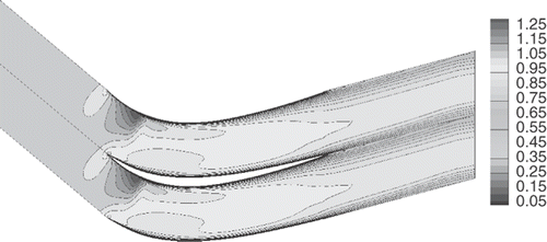
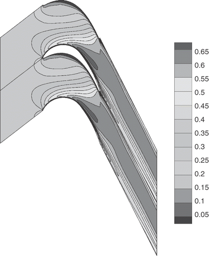
This cascade was first analysed by solving the RANS equations. The resulting Mach contours are presented in and the blade loading and pressure distributions are shown in and . The flow is subsonic and remains attached on both blade surfaces.
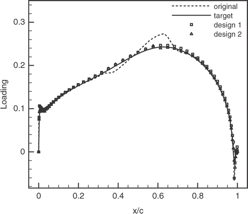
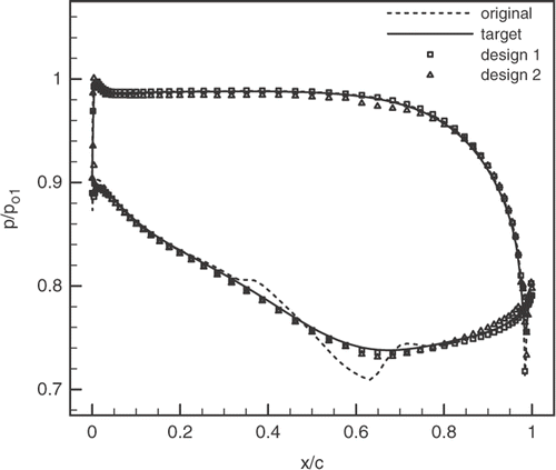
This blade is redesigend using both choices of design variables, one time using the pressure distribution on both blade surfaces and the second time using the blade loading and its thickness distribution. For both redesigns the blade loading distribution is kept the same, which also implies that both redesigns have the same total loading. This loading distribution is obtained by smoothing the original loading between 30% and 70% chord.
The first redesign case converged to a steady-state solution after about 120 geometry modification steps which is similar to that of two analysis calculation, while the second redesign requires about 200 steps to reach a steady-state solution. shows that the target pressure loading has been accurately achieved by both design cases. shows the corresponding pressure distribution on the blade surfaces. The differences between the target and second design case is due to the fact that the target pressure distribution changes during the design so as to satisfy the loading according to Equation (7).
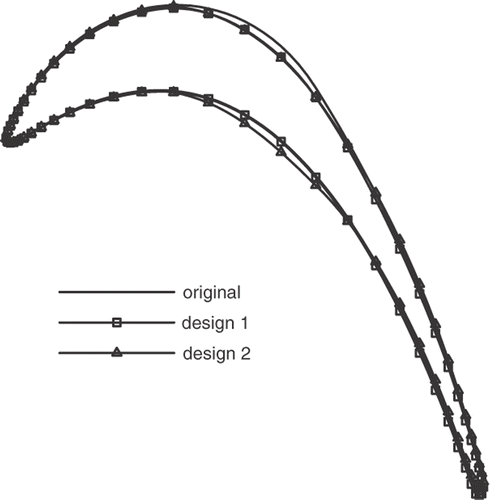
shows a comparison of the original and redesigned blade shapes, where the second redesign has the same tangential thickness as the original one. The redesigned blades have almost the same flow turning as the original blade which was expected by prescribing the same total loading. It can be seen that both redesign cases have reached a similar shape of the blade suction surfaces, however the displacement of the suction surface is also reflected on the pressure surface for the second redesign to keep the blade tangential thickness the same as the prescribed one.
The cascade aerodynamic performance may be expressed by some integral quantities such as the loss coefficient ζ, the load coefficient CL and the reduced mass flow rate . summarizes the aerodynamic characteristics of the original and redesigned cases. The results show that both redesign cases have signficant reduction in the loss coefficients comparing to the original design while blade reduced mass flow rate has increased by 1.3% and 3.5% for the first and second redesigns, respectively. The loading coefficient remains almost the same as a result of the prescribed loading and the blade pressure ratio is almost the same as the original design.
Table 3. Aerodynamic characteristics of DFVLR turbine redesign.
5.3. NASA Rotor 67
The midspan blade section of the NASA transonic compressor rotor that is referred to as Rotor 67 Citation21 is redesigned by modifying the loading distribution keeping the blade thickness fixed. The original blade characteristics and flow conditions at midspan at design conditions are presented in .
Table 4. NASA Rotor 67 data and flow conditions at midspan.
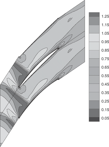
First, the 2D RANS equations were solved, taking into account the streamtube contraction in the radial direction as well as the axial boundary layer growth along the rotor hub and shroud Citation22. The necessary data is provided in Fottner Citation21. shows the Mach number contours around the original compressor rotor, where the flow is supersonic at inlet and a detached shock forms upstream of the blade Citation21. There is no indication of any flow separation on the blade surfaces.
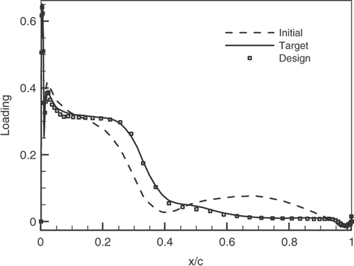
The redesign scenario was focused on modifying the pressure loading in order to lower the total pressure loss coefficient. presents the initial, target and design pressure loadings where, for the target loading, the shock position was moved downstream and its strength was slightly reduced. Furthermore, the pressure loading was smoothed from 50% chord to the trailing edge which was also necessary in order to maintain the same area under the loading curve and hence the same pressure ratio and, implicitly, the same mass flow rate.
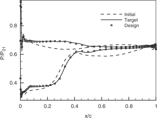
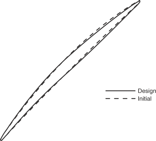
After 500 design steps, which is equivalent to 1.5 analysis computations, the target blade displacement level was reached and hence the target pressure loading. presents the initial, target and design pressure distribution where it can be seen that the changes of the loading curve are also reflected in the corresponding pressure distribution. The difference between initial and design blade shape is depicted in , where both blades have nearly the same flow turning. This was expected as the area under the loading curve was almost unchanged. shows the results of the aerodynamic redesign. The mass flow rate deviates by 0.04% and the inlet Mach number by less than 0.3%, which is well within acceptable limits. The redesigned blade section showed a decrease in loss coefficient which was the primary design goal.
Table 5. Aerodynamic characteristics of the redesigned Rotor 67.
6. Conclusion
An aerodynamic inverse shape design method for turbomachinery blading, applicable to 2D and 3D flows, and consistent with transonic viscous flow, has been presented, assessed and applied to design linear cascades in 2D turbulent flow in the subsonic and transonic regimes. The design variables are either the pressure distributions on blade pressure and suction sides, or the blade loading and thickness distributions. The method is implemented in a consistent manner into the unsteady RANS equations that are solved on a moving mesh using an ALE formulation.
The method robustness and accuracy are first verified by inversely designing an existing transonic compressor cascade. It was also shown that the time-accurate solution procedure has significantly improved the convergence rate of the inverse design method and provides a natural and intuitive approach to the implementation of inverse methods. The usefulness of the inverse method in reshaping the blades to accomplish a specific target distribution is then demonstrated on the redesign of a highly cambered subsonic turbine cascade and on the redesign of a transonic compressor cascade. It was also found that a rather significant improvement in the blade aerodynamic performance can be achieved by carefully tailoring the target pressure/loading distributions.
Acknowledgements
The authors would like to thank Mr B. Roidl for his efforts in redesigning the midspan section of Rotor 67, under the guidance of the second author. The financial support of the National Sciences and Engineering Research Council (NSERC) of Canada, and the ENCS Faculty Support for Research Thesis at Concordia University, are gratefully acknowledged.
References
- Zannetti, L, 1986. A natural formulation for the solution of two-dimensional or axisymmetric inverse problems, Int J. Numer. Methods Eng 22 (1986), pp. 451–463.
- Giles, M, and Drela, M, 1987. Two dimensional transonic aerodynamic design method, AIAA Stud J. 25 (1987), pp. 1199–1205.
- Thompkins, W, and Tong, S, 1982. inverse or design calculation for nonpotential flows in turbomachinery cascades, ASME J. Eng. Power 104 (1982), pp. 281–285.
- Tong, S, and Thompkins, W, 1982. A design calculation procedure for shock-free or strong passage shock turbomachinery cascades. ASME Paper 82-GT-220. 1982.
- Yang, Y, and Ntone, F, 1986. Viscous compressible flow direct and inverse computation with illustration. NASA-CR-175037. 1986.
- Demeulenaere, A, Leonard, O, and Van den Braembussche, R, 1997. A two-dimensional Navier–Stokes inverse solver for compressor and turbine blade design, Proc. Inst. Mec. Eng., A. 211 (1997), pp. 299–307.
- de Vito, L, and van den Braembussche, R, 2003. A novel two-dimensional viscous inverse design method for turbomachinery blading, J. Turbomach. 125 (2003), pp. 310–316.
- Leonard, O, and van den Braembussche, R, 1992. Design method for subsonic and transonic cascades with the prescribed Mach number distribution, Trans. ASME 114 (1992), pp. 553–560.
- Zannetti, L, and Pandolfi, M, 1984. Inverse design techniques for cascades, NASA CR–3836. 1984.
- Dang, T, 1995. Inverse method for turbomachinery blade using shock-capturing techniques. AIAA Paper 95–2465. 1995.
- Damle, S, Dang, T, Stringham, J, and Razinsky, E, 1999. Practical use of a 3D viscous inverse method for the design of compressor blade, J. Turbomach. 121 (1999), pp. 321–325.
- Ahmadi, M, and Ghaly, W, 1998. Aerodynamic design of turbomachinery cascades using a finite volume method on unstructured meshes, J. Inverse Probl. Eng. 6 (1998), pp. 281–298.
- Choo, B, and Zangeneh, M, 2000. Development of an (Adaptive) unstructured 2-D inverse design method for turbomachinery blades. ASME Paper GT-2002-30620. 2000.
- Daneshkhah, K, and Ghaly, W, 2006. An inverse blade design method for subsonic and transonic viscous flow in compressors and turbines, J. Inverse Probl. Sci. Eng. 14 (2006), pp. 211–231.
- Demirdzic, I, and Peric, M, 1988. Space conservation law in finite-volume calculations of fluid flow, Int. J. Numer. Meth. Fl. 8 (1988), pp. 1037–1050.
- Mavriplis, D, Jameson, A, and Martinelli, L, 1989. Multigrid solution of the navier stokes equations on triangular meshes, AIAA Paper 89-0120 (1989).
- Jameson, A, 1991. Time dependent calculations using multigrid, with application to unsteady flow past airfoils and wings, AIAA Paper 91-1596 (1991).
- Giles, M, 1990. Nonreflecting boundary conditions for Euler equation calculations, AIAA stud. J. 28 (1990), pp. 2050–2058.
- Baldwin, B, and Lomax, H, 1978. Thin layer approximation and algebraic model for separated turbulent flows, AIAA Paper 78-257 (1978).
- Mavripilis, D, 1991. Turbulent flow calculations using unstructured and adaptive meshes, Int. J. Numer. Meth. Fl. 91 (1991), pp. 1131–1152.
- Fottner, L, 1990. Test cases for computation of internal flows in aero engine components. AGARD-AR-275. 1990.
- Rangwalla, AA, Madavan, NK, and Johnson, PD, 1992. Application of an unsteady Navier–Stokes solver to transonic turbine design, AIAA J. Propul Power 8 (1992), pp. 1079–1086.
