Abstract
A fully three-dimensional (3D) viscous inverse method for blade design is presented. Built on a time-marching finite-volume direct Navier–Stokes solver, the inverse algorithm employs two extra components to make the solver work in the design mode: an inverse boundary condition on the blade surfaces combined with a camber generation scheme that updates the blade geometry. The inverse blade boundary condition satisfies the prescribed pressure loading by allowing the flow to cross the blade surfaces during the iteration process, and the camber generation scheme subsequently enforces the flow-tangency condition by adjusting the camber surface so that the blade surfaces are properly aligned with the velocity field. To preserve the smoothness and mechanical integrity of the blade, the camber surface is modelled with a series of Bezier curves in the blade span direction. Using the calculated camber surface, the complete blade geometry is then generated from a prescribed blade thickness distribution. Through these techniques, the inverse method has turned into a robust and effective tool to handle full 3D and viscous computation with the end-wall effects, in particular, tip-clearance flow. Numerical experiments show that this inverse algorithm is robust, accurate and efficient.
Nomenclature
| α | = | blade surface coordinate component in tangential direction. |
| θ | = | tangential coordinate |
| ρ | = | density |
| A | = | area |
| c | = | sonic speed |
| f | = | camber wrap angle |
| t | = | tangential thickness of blade |
| = | mass flow rate | |
| p | = | static pressure |
| Δp | = | p+ − p−, pressure loading on the blade |
| r | = | radius |
| V | = | absolute velocity |
| W | = | relative velocity |
Subscripts
| 1 | = | blade leading edge |
| 2 | = | blade trailing edge |
| + | = | blade pressure surface |
| − | = | blade suction surface |
| n | = | direction normal to the blade surface |
| θ | = | circumferential direction |
1. Introduction
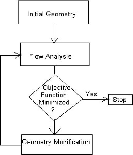
Three-dimensional (3D) blade design and optimization to this day is still very much a trial-and-error process. Such a process can be time consuming and the quality of the final blade is largely dependent on the designers’ experience. One of the main difficulties for this design practice is that the effect of certain geometry modifications on the flow field is not readily known because one small change in blade geometry can significantly alter the interrelated overall 3D flow field. More recently, with the availability of faster and more powerful computers, automated optimization using 3D computational fluid dynamics (CFD) solver becomes possible. This method minimizes the objective function through a large number of trial cases determined by an external optimization procedure, as shown in . One of the advantages of this approach is that designers have all the flexibility in defining the objective function that fits their design intent. However, the large computing resources and the time required to reach the optimized solution is still prohibiting automated optimization in becoming a design tool that can be used in daily engineering design work.
Figure 1. Flow chart for numerical optimization, where the geometry modification is based on numerical minimization scheme, not the flow physics.
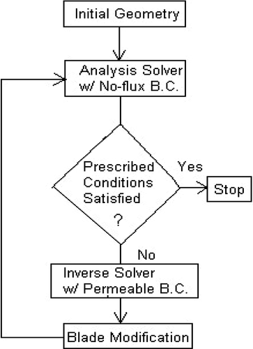
This makes the inverse design scheme an attractive alternative in the design and optimization of 3D blades. The inverse method prescribes certain desired flow conditions as design targets and calculates the blade geometry that satisfies the design goals through an iterative process. The 3D inverse method takes advantage of many robust CFD schemes, such as the control volume method combined with the time-marching algorithm that can be used to solve 3D compressible and viscous flow fields. The main difference between an inverse method and an optimization scheme is the basis on which the blade geometry is modified. An optimization scheme determines the next trial geometry purely based on the numerical minimization of the objective function. The inverse method modifies the blade geometry based on the property of the flow field, typically the velocity vector on the blade surfaces, therefore significantly reducing the number of iterations needed. There are some variances in the overall iteration algorithm in different inverse methods. One of them is the approach adopted by Demeulenaere and Van den Braembussche Citation1 that uses a combination of direct and inverse solvers in an iterative process (). Each iteration loop requires the convergence of both a direct and an inverse solver, and many iterations are needed before the prescribed conditions can be satisfied. This hybrid inverse iteration algorithm, although more efficient than optimization, still requires longer runtime than the corresponding analysis solver.
Figure 2. Flow chart for hybrid inverse method, which requires convergent solutions for both analysis solver and inverse solver in each blade modification iteration (BC–boundary conditions).
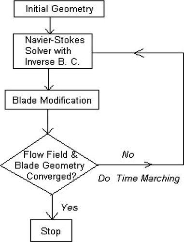
The inverse method described here incorporates the inverse boundary condition and the blade geometry modification in a time-marching iteration procedure (). The advantage of this method is that it is more efficient compared to the hybrid iteration method. As a matter of fact, it will be shown that the time needed for the current inverse method to reach converged solution is of the same order of magnitude as the corresponding direct solver. The challenge of this method, however, is that it requires a robust inverse boundary condition and a blade modification scheme that can handle numerical instability aggravated by the blade geometry modification during time-marching iteration, which is the main focus when the inverse algorithm is discussed in detail in the following sections.
Figure 3. Flow chart for the current inverse method, where the blade modification is an integrated part of the time-marching iteration (BC–boundary conditions).
The inverse method allows users to specify some conditions that fit the design intent. There are two major different choices of prescribed flow conditions in various inverse methods. Demeulenaere and Van den Braembussche Citation1 specify the static pressure distributions on both pressure and suction surfaces. The geometry of both pressure side and suction side of the blade are calculated to match the prescribed pressure profiles. The advantage of this method is that it can control the flow diffusion on the blade surfaces in fine detail on the two-dimensional (2D) airfoil sections, although this is not always the case in 3D where spanwise shifting of streamlines can be large. The main difficulty for this approach, however, is the well-known existence problem: there is no guarantee that realistic blade geometry exists for certain suction and pressure side pressure distributions. Lighthill Citation2 derived three necessary conditions for a solution to exist based on 2D incompressible potential airfoil theory. However, no such equivalent conditions are known for 3D compressible flow.
The other widely used option for prescribed conditions is to specify the mean swirl distribution and the blade thickness distributions in the bladed region. This approach was first proposed by Hawthorne et al. Citation3 and later extended to 3D applications by Borges Citation4, Dang Citation5,Citation6 and Zangeneh Citation7. This choice of prescribed condition not only removes the difficulties associated with the 'existence problem’, but also ensures, to some extent, mechanical integrity by allowing the user to specify the blade thickness distribution. Furthermore, the mean swirl is an important design parameter. The difference between the mean swirl at the blade leading edge and trailing edge is proportional to the torque that the blades apply to the flow.
(1)
Therefore, prescribing the mean swirl profile can satisfy the power input requirement and control the work input schedule along the blade. Also from the above-mentioned equation, the gradient of the mean swirl is related to the pressure loading Δp (or local difference in pressure across the blade). Pressure loading, and the corresponding velocity difference on the pressure and suction surfaces, is one of the most important parameters affecting the aerodynamic performance of the blade row. The velocity difference can be related to the secondary flow in the passage and the flow deviation (Eck Citation8, Qiu et al. Citation9). The larger the blade loading, the stronger the secondary flow and the flow deviation. Aungier Citation10 also derived an equation that explicitly relates the diffusion ratio on the suction surface to the blade loading. All this suggests that the blade loading is an important parameter that designers have to reckon with in the design process. For this reason, the current inverse method specifies the pressure loading on the blade surface as the prescribed condition, which was first proposed by Dang Citation5.
The inverse method described in this article is an extension of the work by Dang et al. Citation6 and Damle Citation11. The main focus of this article is to lay out a comprehensive inverse design methodology that works under the scope of 3D viscous flow application. Although no design example using this method will be presented here, it is worthwhile mentioning that the described method has been successfully applied in several design applications that have previously been reported, such as the design of an aspirated transonic rotor Citation12 as well as highly loaded multistage transonic compressors Citation13–15. Interested readers are invited to examine them.
2. Numerical algorithm of the inverse method
2.1. The basic flow solver
The core flow solver for the current inverse method is based on the conservative form of the 3D Navier–Stokes equations. The solver uses conventional control-volume discretization along with a time-marching integration scheme. The numerical approximation is second-order accurate in space using central difference for flux evaluation. Blended the second- and fourth-difference artificial dissipation model by Jameson et al. Citation16 is used to ensure numerical stability. The residual smoothing technique is also used in improving convergence history.
A standard version of the Baldwin–Lomax model is used for the turbulence model. The Baldwin–Lomax model computes the turbulent viscosity based on the inner and outer boundary layer flow region. This model was chosen because of its simplicity and its success in simulating a wide range of turbomachinery applications near the design point, where large flow separation is not present. The shear stress at the wall is calculated by assuming that the first cell away from the solid surfaces lies in the log–law region of the turbulent boundary layer Citation17.
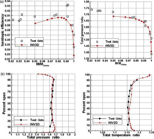
A software program called INV3D has been developed at Syracuse University based on the method described in this article. The program can be run in either direct analysis mode or inverse design mode, which share the same core solver and flow model. Extensive validation effort has shown that the core solver of INV3D has adequate accuracy in predicting complex turbomachinery flows. The validation study of INV3D with the NASA Rotor 67 is summarized here as an example. The computational model consists of a single-block H-type mesh of size 102 × 40 × 40, a total of about 163,200 cells. The tip clearance is modelled with three cells in the radial direction. The choking condition is predicted at a mass flow rate of 34.34 kg s−1, about 1.8% less than the test data. Comparison between the test data and INV3D prediction are shown in . Good agreement can be found in the overall total pressure ratio and adiabatic efficiency, as well as the circumferentially mass-averaged spanwise profiles of total pressure and total temperature at near peak efficiency point. The level of accuracy exhibited in these figures is typical of CFD analysis programs employing the Baldwin–Lomax turbulence model.
2.2. Inverse blade boundary condition
Sharing the core solver, one of the main differences between the direct mode and the inverse mode is how the blade boundary condition is formulated. In the direct method, the flow tangency condition (or no flux condition) is enforced on the blade surfaces.
(2)
This condition cannot be applied directly in the inverse mode because an extra condition, the prescribed loading condition, needs to be satisfied. A method is therefore needed to replace Equation (Equation2
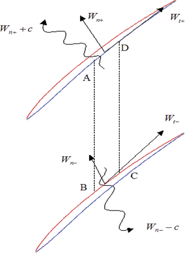
(2) ). If we assume that the normal velocity component, Wn, is subsonic, there is always at least one outgoing wave relative to the calculation domain for each blade surface (). On the pressure surface, corresponding to the outgoing characteristic variable Wn+ + c, the following compatibility relation derived by Van den Braembussche Citation18 can be used to update the new values of normal velocity (Wn) and pressure (p).
(3)
Similarly, on the suction side of the blade, the following compatibility relationship exists for the outgoing wave Wn− − c.
(4)
Strictly speaking, the above characteristic relationships are derived from the Euler equations and are therefore only valid for inviscid flows. However, the waves under consideration are normal to the blade surfaces, in that direction the viscous force can be ignored and the Riemann variables are approximately conserved. This justifies the use of Equations (Equation3
(3) ) and (Equation4
(4) ) even in the highly viscous blade boundary layer regions.
Furthermore, assuming steady state conditions, mass conservation in the control volume ABCD in can lead to the following approximate relationship between the normal velocities on the blade surfaces.
(5)
Combining Equations (Equation3–5
(3) ), we can obtain a method for calculating the normal velocity on the blade surfaces.
(6)
Equation (Equation6
(6) ) replaces the flow tangency condition specified in Equation (Equation2
(2) ) for the inverse method. Generally, the normal velocity on the blade surface according to this equation is non-zero. To make the right-hand side of Equation (Equation6
(6) ) zero so that the flow tangency condition can be eventually satisfied, the following two conditions can be enforced:
(7)
(8)
Equation (Equation7
(7) ) will be satisfied when the prescribed pressure loading condition is enforced during each iteration. Equation (Equation8
(8) ) can be satisfied through the blade geometry modification and therefore constitutes the control equation for the camber generation scheme that will be discussed in detail in the next section.
The static pressure on the blade surface can now be readily calculated from Equations (Equation3(3) ) and (Equation4
(4) ) with the normal velocity Wn known.
(9)
(10)
Other flow variables, such as tangential velocity, density and enthalpy, are extrapolated from the computational domain. Note that this kind of extrapolation is not strictly correct under the permeable boundary condition approach developed by Van den Braembussche Citation18. When the flow normal velocity Wn is going into the calculation domain (i.e. Wn is negative), the blade surface becomes an inlet boundary and all the flow variables except for one must be specified as physical conditions. The current scheme ignores those incoming waves associated with the negative Wn. This is justified because the next step in the current method is to adjust the blade geometry so that the blade normal velocity becomes zero, where specifying more physical conditions becomes unnecessary.
2.3. Camber generation scheme
2.3.1. Camber surface control equation
The ultimate goal of an inverse method is to produce a blade geometry that satisfies the user-prescribed flow conditions. Through the inverse boundary condition in Equations (Equation6(6) ) and (Equation7
(7) ), the prescribed loading condition is enforced. The blade geometry can be obtained using a camber control equation (Equation Equation8
(8) ), which produces a blade geometry that satisfies the requirement of the flow tangency condition. For simplicity, we assume ρ + c + ≈ρ − c− and Equation (Equation8
(8) ) can be rewritten in the following form:
(11)
where α is the blade surface coordinate and is defined as
(12)
Here f is the camber wrap angle and t is the blade tangential thickness. Substituting Equation (Equation12
(12) ) into (Equation11
(11) ), a camber wrap angle (f) differential equation on the meridional plane (z, r) can be obtained.
(13)
where
and
In the above relations, (U,V) are the average blade surface velocities in the axial and radial directions. To solve Equation (Equation13
(13) ) with the known velocity field (U,V) to obtain camber wrap angle f, it requires finite velocity values at the blade surfaces. However, viscous flows imply that the velocity is zero on the boundary surfaces (i.e. no-slip condition). To overcome this difficulty, the velocity vector in Equation (Equation13
(13) ) is calculated based on the velocity at the centre of the first cell away from the blade surface. As we mentioned earlier, the first cell centre is located in the logarithmic region with a corresponding Y+ value of 100–200. Clearly, this approximation is only adequate if the flow is not massively separated. Fortunately, in practice, a well-designed blade should not have massive flow separation at the design point, which is the flow regime, where inverse methods are employed.
Equation (Equation13(13) ) takes a hyperbolic form with a source term. With the stacking line predefined by the user, the equation can be integrated to solve for the whole camber surface, at least theoretically. The challenge is how to handle the difficulties introduced by the 3D viscous effect, which make the straightforward integration of Equation (Equation13
(13) ) numerically unstable. The magnitude of the average blade surface velocity in the end-wall regions can be small because of the effects of the viscous boundary layer or flow separation. The idea of tracing the stream surface in the region where the blade surface velocity is small means that Equation (Equation13
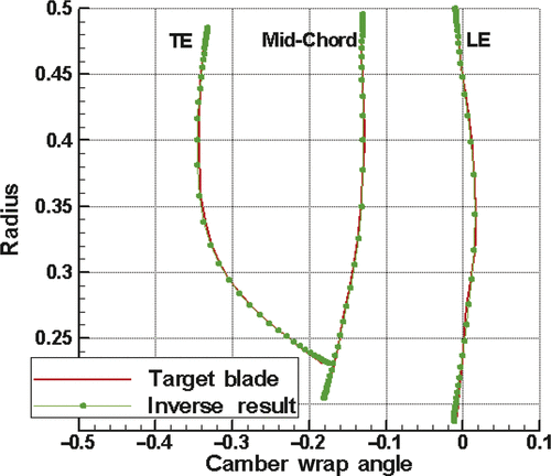
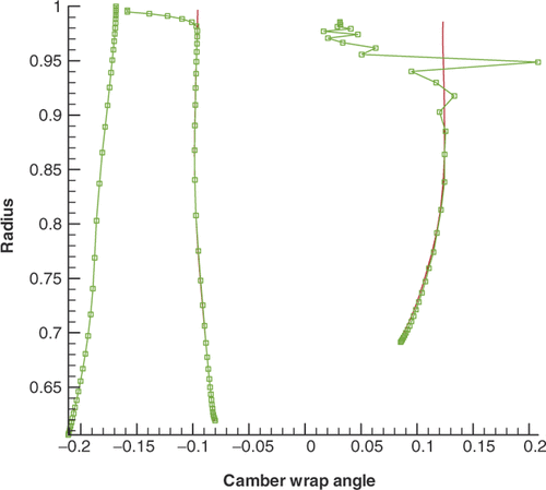
(13) ) is ill-conditioned and that the camber angle would be susceptible to small perturbations in the flow field during the inverse iteration process. This problem becomes worse with the presence of a tip-clearance flow. The strong 3D tip-clearance flow field makes the blade increasingly twisted near the tip and renders it impossible for the camber generation scheme to come up with a blade that is smooth enough for the solver to continue. illustrates the difficulty faced with a straight-forward integration scheme when designing a rotor blade with a tip clearance. The plot shows the wrap angle profile for the leading edge, the mid-chord and the trailing edge. The blade becomes excessively oscillatory towards the trailing edge near the tip region, and the solver cannot continue after a few hundred iterations.
Figure 6. Numerical instability in camber generation when tip clearance is present. The circles represent the camber wrap angle calculated from the direct integration of camber control equation (Equation Equation13(13) ).
2.3.2. Minimization of the blade surface normal velocity
To make the overall 3D viscous inverse algorithm work, an ideal camber surface generation scheme must satisfy the following conditions. First, it must be robust enough to handle local stagnation points or highly irregular flow fields. Second, the resulting surface must be smooth for structural and manufacturing considerations. Finally, the scheme must be fast enough to fit in an iteration process. Numerous attempts have been made to solve Equation (Equation13(13) ) using conventional upwind or central finite difference schemes and none has been proved truly successful. To achieve a robust camber generation scheme, a new approach is needed.
It is easy to see that the direct application of Equation (Equation13(13) ) to each cell will certainly fail if a stagnation flow point is encountered. These kinds of numerical instability can be avoided if the adjustment of a blade surface point is not based on the velocity vector of one individual cell, but is instead based on a series of cells in its neighbourhood. This observation leads to the idea of minimizing the summation of the normal blade velocity.
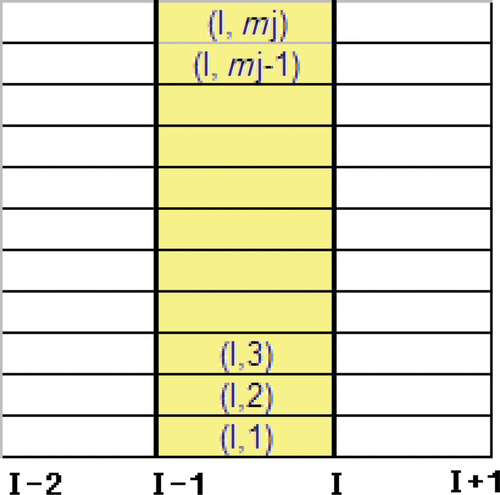
The current camber surface generation procedure involves marching from the stacking line to the leading and trailing edges of the blade to solve for the camber wrap angle f. For simplicity, only the formulation for forward marching, i.e. marching from the stacking line to the trailing edge (), is presented here. A similar formulation can be derived for backward marching. In , the wrap angle f is assumed to be known everywhere on Line (I − 1) either from the previous iteration step or from the prescribed stacking line. Between Line (I − 1) and Line I (the shaded area) are mj cells from (I, 1), (I, 2) to (I, mj) where the velocity vectors are known. The objective here is to find a wrap angle profile for Line I, which will result in a surface (the shaded area) that minimizes the summation of the normal velocity. From Equation (Equation13(13) ), the objective function can be readily defined as:
(14)
Using a central differential scheme to discretize the derivatives in the above-mentioned equation, one can obtain
(15)
where
(16)
2.3.3. Bezier curve model
The goal now is to find a wrap angle profile fi,j along Line I, which will minimize Equation (Equation15(15) ). To do so, a curve model for Line I is needed. The Bezier representation is used here because it can accurately represent any free-form curve shape with a small number of control points. The user has direct control over the smoothness of the curve through the degree of the curve and the number of control points. The camber wrap angle in a spanwise direction can be expressed with a Bezier curve model as follows:
(17)
Here s is a parameter between (0,1) on the parametric space. Nk(s) is the Bezier basis function, Pk are the control points, and the number of control points is nc. Evaluating a Bezier curve is beyond the scope of this article; interested readers can learn the details of this topic in Piegl and Tiller Citation19. Substituting for f from Equation (Equation16
(16) ) into (Equation15
(15) ), one obtains for all the cells between (I − 1) and I:
(18)
where
(19)
and ai,j,bi,j and ci,j are defined in Equation (Equation15
(15) a), while si,j is the parameter corresponding to node (i, j).
2.3.4. Solving for the control points
The next step is to adjust the control points Pk so that Equation (Equation17(17) ) gets minimized. It is immediately clear that this equation is a merit function of a general linear least-squares fitting problem, where one feeds mj sets of data (s, c) into the equation
(20)
to find the nc coefficients Pk that will best fit the data set. In other words, the solution of the least-squares fitting problem defined by Equation (Equation19
(19) ) will produce a series of control points Pk that will minimize the function defined in Equation (Equation17
(17) ) and therefore the normal velocity on the blade surface.
The least-squares-fitting problem is solved using a technique called singular value decomposition (SVD) Citation20. SVD solves a system of linear equations, such as Equation (Equation19(19) ) in this case, where the nc coefficients, Pk, are being determined through mj equations.
Once the control points have been solved through the SVD scheme, the wrap angle along Line I can be evaluated through Equation (Equation16(16) ). The above-described procedure is then repeated marching forward to the trailing edge, through which the summation of the normal velocity is minimized for the camber surface. After the camber surface is updated, the pressure surface and suction surface of the blade are obtained by offsetting the camber surface by half of the local thickness in the tangential direction. A mesh is then regenerated for the new blade and this completes one inverse design iteration. With the new blade and mesh, a new iteration starts. Once again the flow may be crossing the new blade boundaries after the loading condition is enforced, and the geometry needs to be modified. This process continues until the camber surface is no longer getting modified and the flow is settled everywhere. At this point the inverse design is converged.
3. Inverse algorithm verification
To validate the described algorithm, a target-shooting experiment is set up as follows. NASA Rotor 67 is selected as the target blade, which is a 22-blade transonic rotor. The tip clearance is 0.64% of the total span. The total pressure ratio of the rotor is 1.65. The inlet condition of the rotor including total pressure, total temperature and flow angles were obtained from a data match of the experimental data. At the exit, the hub static pressure was specified and simple radial equilibrium was solved. The target blade is analysed at the operating point near the peak efficiency using the direct mode of INV3D to obtain the loading profile. Then another blade is chosen (referred to as the initial blade in this section) with a geometry different from the target blade. Now taking the loading profile, the thickness distribution and a stacking line from the target blade as input, a calculation in the inverse mode is started with the initial blade (which is different from the target blade). In the inverse run, all the inlet and outlet flow conditions are kept exactly the same as in the analysis run for the target blade. The spanwise camber line is modelled by the third degree Bezier curve with six control points. If the method works correctly, the geometry resulting from the inverse design should be the same as the target blade, because the prescribed loading condition is the same as that of the target blade. The results follow.
3.1. Accuracy
plot the initial blade, target blade and the blade generated by the inverse method at the hub, midspan and tip section. Starting from a different initial blade shape, the blade produced by the inverse run falls right on top of the target blade at all three spanwise locations. A closer look at the camber wrap angle () confirms that the resulted camber surface overlaps that of the target blade everywhere on the blade.
Figure 8. Blade geometry at (a) hub, (b) midspan and (c) tip. Solid line: target blade; Dash line: initial blade; Circle: blade produced by inverse method.
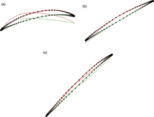
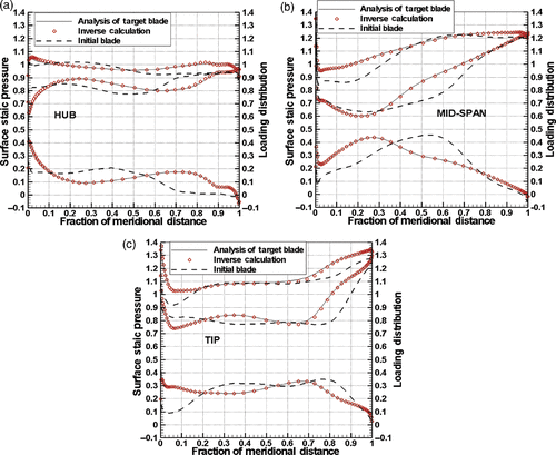
The inverse algorithm attempts to accomplish two tasks. First, it enforces the prescribed pressure loading condition. Second, it enforces the flow-tangency condition through adjusting the camber surface. show the static pressure and pressure loading profiles at blade hub, midspan and tip. From the plots, the pressure loading from the inverse calculation (symbols) compares very well with that from the analysis results of the target blade (solid lines). Similarly, the static pressure profiles produced by the inverse design (symbols) are also closely comparable with that of the target blade (solid lines).
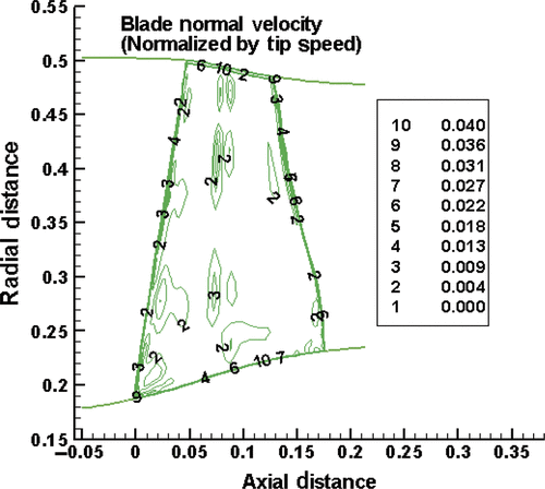
It is interesting to check the normal velocity on the blade surfaces. Ideally, after the inverse run converges, the blade normal velocity should become zero. This is not the case in the current scheme because the flow tangency condition is only approximately enforced through the camber generation scheme. However, the normal velocity is expected to be very small. shows the normal velocity on the blade suction surface. It can be seen that the maximum normal velocity on the blade when the inverse run converges is about 4% of the blade tip speed, which occurs near the blade hub and tip regions. This is apparently the result of the strong 3D flow in the tip clearance and end-wall regions. For the majority of the blade surface, however, the normal velocity is less than 0.4%, which suggests that the flow-tangency condition is satisfied with reasonable accuracy.
3.2. Consistency
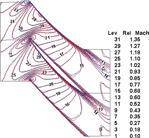
For inverse design being useful, the flow solution obtained by the inverse run should be the same as the result produced by the corresponding analysis run. Despite the approximate enforcement of flow tangency condition (through minimization), this consistency is confirmed in , where the pressure distribution from the analysis run and inverse run are the same. To further demonstrate this important fact, shows the comparison of Mach number contours at the blade midspan. The solid line is from the inverse run and the dashed line is from the corresponding analysis run. Their agreement proves a good consistency between the analysis and inverse runs.
3.3. Efficiency
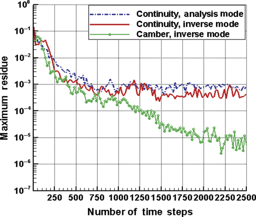
One of the greatest advantages of the current method is how fast one can obtain a design with the specified loading. is a comparison of the convergence history of the analysis run (for the target blade) with that of the inverse run. While the solution of flow field was converged for the inverse run, the maximum residual of the modification of the camber wrap angle is down to the order of magnitude of 10−5. The flow field of the initial blade was used as initial guess for both calculations. It can be seen that the number of iterations required for the analysis and inverse runs is almost the same. Because of the extra time consumed in camber modification and overall grid regeneration in each iteration, the inverse method takes about 15–25% more time than its corresponding analysis mode, depending on the size of the mesh. This is a rather small price to pay compared to a typical CFD optimization or other inverse methods.
4. Conclusions
The algorithm of a 3D viscous inverse blade design method is discussed in detail. The method is based on the conventional CFD analysis method with adjustment to the blade boundary condition. The prescribed pressure loading condition is enforced through an inverse blade boundary condition, which is derived from the compatibility relationship of the two always-outgoing waves on the pressure and suction surfaces. The flow tangency condition is then enforced through the camber control equation (Equation Equation14(13) ). In order to avoid numerical instability problems that arise when viscous and clearance-flow effects are included, the camber equation is converted into a linear least-square fitting problem that essentially minimizes the sum of the normal velocity on the blade surfaces. To model the camber surface, the radial grid lines are represented by Bezier curves. This not only provides the robustness critical to the success of the inverse method, but also gives the user control over the smoothness of the blade, which is important to designers for aerodynamic and structural considerations.
The target-shooting exercise for Rotor 67 has shown that the described method is accurate, consistent and efficient. First and most importantly, it shows that the inverse method can effectively drive a different blade shape to a new one that satisfies the prescribed pressure loading condition. Second, the exact reproduction of the target blade flow field in the inverse run proves that the inverse flow solver is consistent with the analysis solver, which means that the calculated blade has the flow property that the designer is seeking. Furthermore, the finite normal velocity on the blade surface is sufficiently small, which confirms the legitimacy of using the minimization scheme to satisfy the flow-tangency condition. Finally, the described inverse algorithm has proved to be very efficient and is only 15–25% slower than its corresponding analysis run.
In summary, the main contribution of this work is as follow. By introducing inverse boundary condition and the minimization technique to satisfy the zero normal velocity on the blade surfaces, it has turned the inverse method into a robust and effective tool to handle full 3D and viscous computation with the end-wall effects, in particular tip-clearance flow.
References
- Demeulenaere, A, and Van den Braembussche, R, 1996. Three-dimensional Inverse Method for Turbomachinery Blading Design. ASME Paper No. 96-GT-39. 1996.
- Lighthill, MJ, 1945. A New Method of Two Dimensional Aerodynamic Design. ARC R&M 2140. 1945.
- Hawthorne, WR, Tan, CS, Wang, C, and McCune, JE, 1984. Theory of blade design for large deflections: Part I–two dimensional cascades, ASME J. Eng. Gas Turbine Power 106 (1984), pp. 346–353.
- Borges, JE, 1990. A three-dimensional inverse method for turbomachinery: Part 1, ASME J. Turbomachinery 112 (1990), pp. 346–354.
- Dang, T, 1993. A fully three-dimensional inverse method for turbomachinery blading in transonic flows, ASME J. Turbomachinery 115 (1993), pp. 354–361.
- Dang, T, Damle, S, and Qiu, X, 2000. Euler-based inverse method for turbomachine blades–part 2: Three-dimensional flows, AIAA J. 38 (2000), pp. 2007–2013.
- Zangeneh, M, 1994. Inviscid–Viscous interaction method for 3D inverse design of centrifugal impellers, ASME J. Turbomachinery 116 (1994), pp. 280–290.
- Eck, B, 1973. Fans. Pergamon, Germany. 1973.
- Qiu, X, Mallikarachichi, C, and Anderson, M, 2007. A New Slip Factor Model for Axial and Radial Impellers. ASME Paper No. GT2007-27064. 2007.
- Aungier, RH, 2000. Centrifugal Compressors. New York: ASME Press; 2000.
- Damle, S, 1998. Fully Three-Dimensional and Viscous Inverse Method for Turbomachinery Blade Design. Ph.D. Dissertation. Syracuse University; 1998.
- Dang, TQ, van Rooij, MPC, and Larosiliere, LM, 2003. Design Study of Aspirated Compressor Blades Using 3D Inverse Method. ASME Paper No. GT2003-38492. 2003.
- Medd, AJ, Dang, TQ, and Larisoliere, LM, 2003. 3D Inverse Design Loading Strategy for Transonic Axial Compressor Blading. ASME Paper No. GT2003-38501. 2003.
- van Rooij, MPC, Dang, TQ, and Larosiliere, LM, 2007. Improving aerodynamic matching using a 3D multistage inverse design method, ASME J. Turbomachinery 129 (2007), pp. 108–118.
- van Rooij, MPC, Dang, TQ, and Larosiliere, LM, 2008. Enhanced Blade Row Matching Capabilities via 3D Multistage Inverse Design and Pressure Loading Manager. ASME Paper No. 2008-50539. 2008.
- Jameson, A, Schmidt, W, and Turkel, E, 1981. Numerical Solution of the Euler Equations by Finite Volume Method Using Runge-Kutta Time-Stepping Schemes. AIAA Paper No. 81-1259. 1981.
- Denton, JD, 1992. The calculation of three-dimensional viscous flow through multistage turbomachines, ASME J. Turbomachinery 114 (1992), pp. 18–26.
- Van den Braembussche, R, Numerical Methods for Flow Calculation in Turbomachinery. Report on Lecture Series1994–06. Belgium: Von Karman Institute.
- Piegl, L, and Tiller, W, 1997. The NURBS Book. New York: Springer-Verlag; 1997.
- Press, WH, Teukolsky, SA, Vellerling, WT, and Flannery, BP, 1992. Numerical Recipes in FORTRAN. Cambridge: Cambridge University Press; 1992.
