Abstract
The thermal state at a solid–solid contact with interfacial heat generation requires the knowledge of two contact parameters: the thermal contact resistance (RTC), and the partition coefficient of the generated heat flux at the interface (α). RTC has been intensively studied and is now defined by many theoretical models. On the other hand, α did not profit from as much interest and was never studied in the case of electrothermal contact. In this article, an inverse analysis and an experimental approach intended to estimate RTC and α are presented. The method is based on the minimization of a least squares criterion by using a Gauss–Newton algorithm. The inverse analysis shows that RTC and α are highly correlated. Choosing an adequate time interval of measurements can reduce the correlation coefficient. The optimal extent of this interval depends on the parameter values to be estimated. An experimental device is carried out. The weak dispersion of the temperature recordings and the estimated parameters shows the good reliability of the experiment and of the estimation method.
Nomenclature
| ai: | = | thermal diffusivity of material i (m2 s−1) |
| bi: | = | thermal effusivity of material i (W m−2 K s1/2) |
| cc: | = | correlation coefficient |
| cpi: | = | specific heat of material i (J kg K−1) |
| F: | = | force (N) |
| f: | = | function of constriction |
| Li: | = | distance between boundary condition thermocouple and interface in material i (m) |
| Pi: | = | voluminal dissipated heat flux in material i (W m−3) |
| RTC: | = | thermal contact resistance (m2 K W−1) |
| REC: | = | electrical contact resistance (Ω m2) |
| SR: | = | measurement sensitivity to RTC (W m−2) |
| Sα: | = | measurement sensitivity to α (K) |
| tw: | = | estimation window (s) |
| = | measured temperature by thermocouple j in material i (°C) | |
| = | position of thermocouple j in material i (m) | |
| α: | = | partition coefficient of generated heat flux at the interface |
| ϕg: | = | generated heat flux at the interface (W m−2) |
| λi: | = | thermal conductivity of material i (W m K−1) |
| θi: | = | temperature of water box i (°C) |
| ρei: | = | electrical resistivity of material i (Ω m) |
| ρi: | = | density of material i (kg m−3) |
| σi: | = | electrical conductivity of material i |
| i | = | = 1, 2 |
| j | = | = 1, 2. |
1. Introduction
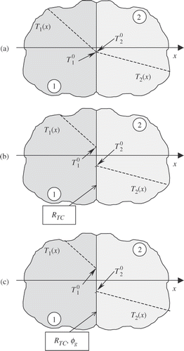
The thermal state at a solid–solid contact depends on the contact characteristics. In the hypothetical case of a perfect contact (), the equations are well known: they are the temperatures continuity equation (1), and the conservation of heat flux transmitted by conduction through the interface (2).
(1)
(2) When the contact is imperfect (interstitial defects, surface irregularities) (), the thermal field presents a discontinuity at the interface. Thus the condition (1) must be replaced by an homogeneous coupling condition of Fourier type (3), where the temperature discontinuity at the interface is proportional to the heat flux transmitted by conduction. The proportionality coefficient, called thermal contact resistance (RTC), characterizes the thermal imperfection of the contact.
(3) Finally, if the contact is imperfect and is the site of heat generation (sliding contact, electrothermal contact, etc.), a fraction α (<1) of the generated heat flux also contributes to the temperature discontinuity at the interface. Consequently, Equation (3) becomes a non-homogeneous coupling condition of Fourier type (4) involving the new parameter α.
(4)
The bibliography reveals that for a long time electrical contact has aroused interest Citation1,Citation2, but in spite of that, the thermal aspect of the contact condition has not been studied at all. However, the definition of α has undergone a significant evolution that one finds primarily in studies on the sliding contacts. Mazo et al. Citation3, Mazo Citation4 and Badie-Levet Citation5 initially defined α in the case of sliding contact as a ‘partition coefficient of the generated heat flux by friction at the interface’. More recently, on the same subject, Bardon Citation6 introduced the concept of ‘part of the generated heat flux that takes part in the temperature jump’. Still in the case of the sliding contact, this concept, probably intrinsic to the interface, was taken again thereafter by Chantrenne and Raynaud Citation7 who consider that the heat flux is generated in a volume subjacent with the interface. Laraqi Citation8 proposes an approach of the heat flux generation by friction based on a Gaussian distribution of the dissipation zones, but the problem concerning the characterization of the heat sources intensity remains open. Bauzin and Laraqi Citation9,Citation10 did an experimental study to estimate simultaneously α, φg and RTC in the case of a sliding contact. They supplemented their study by simulation in various configurations Citation11–13. Recently we proposed a theoretical model of α based on a microscopic approach of the electrothermal contact in steady state Citation14. The modelling results show that α is a combination of the contact properties playing a role in the heat generation (electrical resistivities) and in the heat transfer by conduction (thermal conductivities). Thus, according to this model, α is independent of the external thermal boundary conditions and of the interface structure.
With a view to validating this model, we have developed an experimental methodology that allows the simultaneous estimation of both contact parameters. This methodology is based on a precise instrumentation by thermocouples and an inverse analysis using a Gauss–Newton algorithm. The main goal of this article is to present the experimental approach and the results of the model validation. This work constitutes the first attempt to estimate the two highly correlated parameters RTC and α in the case of the electrothermal contact.
This text is organized into four sections. In the first one, the measurement principle is described. The second is devoted to sensitivity analysis. In the third section, we present the results of the inverse analysis that permits the optimization of the parameters estimation. In the last section, the experimental approach is described and the first results show the reliability level of the contact parameters estimation.
2. Measurement principle of the contact parameters
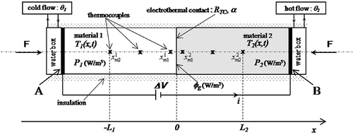
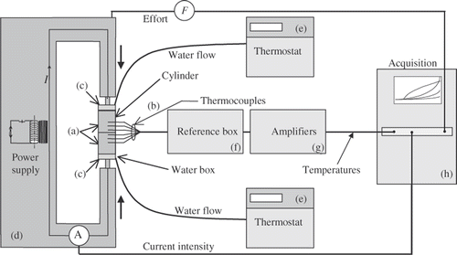
The measurement of the parameters RTC and α is based on the analysis of the transient thermal response of two cylinders of the same geometry in imperfect contact heated by the Joule effect (). The two cylinders are aligned and clamped together by a press, which applies a normal force F. The cylinders can carry a heat flux and/or an electrical current. The electrical current is provided by a stabilized power supply connected to electrodes at the two ends of the cylinders. Two water boxes supporting water flows maintained at temperatures θ1 and θ2 control the heat flux. The side surface is thermally insulated.
The contact at x = 0 is imperfect. It is thus the site of an electrical contact resistance that opposes the current and of a thermal contact resistance that opposes the heat flux. The electrical contact resistance REC is supposed to be known from an auxiliary measurement Citation15. It determines the generated heat flux density ϕg (W m−2) at the interface x = 0 when an electrical current crosses the contact. In the same way, the thermophysical characteristics of both materials are assumed to be known and uniform in particular the electrical resistivities, which determine the source densities P1 and P2 (W m−3) Citation16,Citation17.
Numerical simulations enabled the size of the cylinders to be chosen. The latter have a diameter of 20 mm and a height of 50 mm. This size of cylinders ensures a uniform source term in the Equation (5a). The assumption of a one-dimensional heat flow retained in the Equation (5a) is thus respected. The side surface of the cylinders is insulated massively. Uniformity of temperature field within the sections of cylinders has been numerically and experimentally checked in a previous detailed study Citation14.
The intensity of the current I was selected so that the maximum temperature increase does not exceed 50 K. That goes from pair with thermo physical properties variations, which remain lower than 3% Citation16,Citation17. Consequently, we consider those properties constant during experiments.
With such a device, the estimation of RTC and α can be carried out by means of a one-dimensional transient linear conductive model defined on the domain [−L1; L2] for t > 0, and by the measurement of the temperature field on both sides of the interface along the cylinders’ axis at selected points Citation14. Points x = −L1 and x = L2 are equipped with thermocouples which record the temperatures and
, respectively. Thus, we consider boundary conditions of the first kind at these two points. The linear system describing the heat transfer in the device can be formulated as follows:
(5)
(6)
(7)
(8)
(9)
(10)
(11)
(12)
(j = 1, 2) represent the initial temperature distribution in the domain [−L1, L2] before the passage of the electrical current. The boundary condition at the interface x = 0 is composed of two equations: the heat flux conservation equation (5d) and a condition of the third kind (5e). It is the latter which interests us since it expresses the temperature jump at the interface as a function of the two sought parameters RTC and α.
The estimation of RTC and α is based on the solution of the inverse heat conduction problem whose direct problem is given by the equations system (5). The solution of the inverse heat conduction problem will be based on the knowledge of the following data:
| • | Two temperature recordings within cylinder 1, denoted | ||||
| • | The voltage recording (current intensity is imposed and known). | ||||
| • | The electric and thermal characteristics of materials are supposed to be known, uniform and constant Citation16,Citation17. | ||||
3. Sensitivity analysis
The sensitivity coefficients with respect to the parameters RTC and α will be denoted SR and Sα, respectively. The sensitivity coefficients are defined as:
(13)
(14) where subscript j = 1, 2 refers to the considered cylinder.
SR is homogeneous with a heat flux density (W m−2), and the dimension of Sα is the same as temperature (K). To compute the sensitivity fields, one derives successively the equations of the system (5) according to RTC and α in accordance with relations (6) before discretization. Derivation before discretization permits to reduce the number of numerical operations and thus minimize calculation time and round errors Citation18. The equations system (7) describing the sensitivity field with respect to RTC is similar to system (5) except Equation (7e), which does not have the same shape of Equation (5e).
(15)
(16)
(17)
(18)
(19)
(20)
(21)
(22) Thus, for a given material couple, one has:
(23)
In the same way, the equations system (9) describing the sensitivity coefficient field with respect to α is similar to the system (5) except Equation (9e) that does not have the same shape of Equation (5e).
(24)
(25)
(26)
(27)
(28)
(29)
(30)
(31)
Thus, for a given material couple, one has:
(32)
Also, the unknown parameters RTC and α appear in Equations (7e) and (9e); thus, the problem of estimating RTC and α is non-linear and involves an iterative procedure.
The sensitivity analysis is based on the experimental data listed in . For RTC, one considers a field of typical values in the case of a dry metal–metal contact: 10−6 ≤ RTC ≤ 10−3 km2 W−1. The values of ϕg, ranging between 10 and 30 kW m−2, are selected so that the heating of the control volume remains ranged between 0 and 50 K (linear problem). The partition coefficient α varies from 0 to 1.
Table 1. Experimental data.
3.1. Measurement sensitivity with respect to the RTC
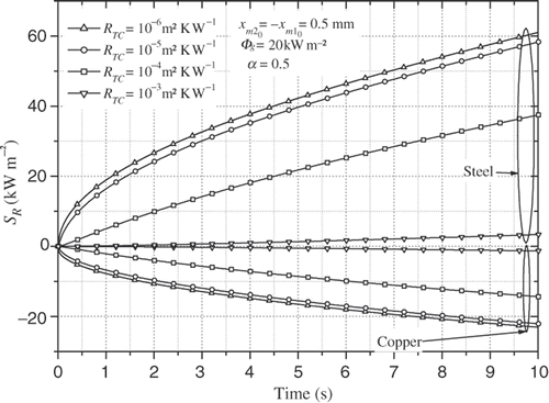
shows SR versus time at both measurement points, x-coordinates of which are and
(
= 0.5 mm), for various values of the RTC. Taking into account the boundary conditions (
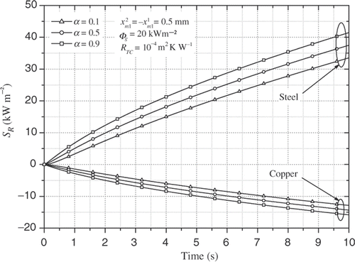
), an increase in the RTC value generates a positive variation of the temperature field in material 2 and a negative one in material 1. Consequently, SR is positive in material 2 and negative in material 1. The absolute value of SR is monotonically increasing with time and decreasing with RTC. The timescale retained in this calculation (10 s) is of the same order as the value of the fundamental time-constant of the studied thermal system. One notes that SR has appreciable levels of value: about several tens kW m−2, much higher than the detection threshold of flux-meters (about a few hundred watts). For a given value of the RTC, SR is maximum in steady state. The sensitivity related to the measurement point in copper is definitely lower (in absolute value) than that related to the measurement point in steel. This is due to the significant thermal conductivity of copper compared to that of steel.
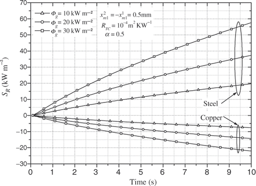
shows the time evolution of SR for RTC = 10−4 Km2 W−1 and three values of φg. It reveals that SR is monotonically increasing with φg. That result was expected since according to (5e), the more significant φg is, the more a variation of RTC generates an important variation of the temperature field.
shows the time evolution of SR for RTC = 10−4 m2 K W−1 and three values of α. One can see that SR is monotonically increasing with α. That result was also awaited since α and φg have the same role in (5e).
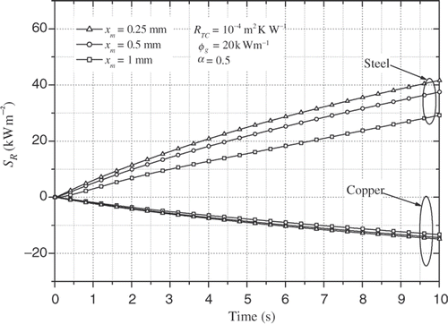
We also checked that SR is decreasing when the measurement points are increasingly far away from the interface. shows that SR decreases linearly with the distance between sensor location and interface. Variations of SR are less significant in copper because of its important thermal conductivity that reduces considerably the SR gradient.
3.2. Measurement sensitivity with respect to α
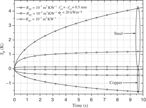
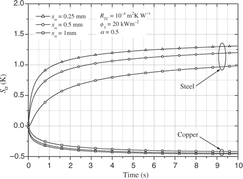
shows the sensitivity coefficient of α on the same time scale. Like SR, Sα is monotonically increasing with time, but it is monotonically increasing with RTC. That result was expected since according to (5e), the more significant RTC is, the more a variation of α generates a significant variation of the temperature field.
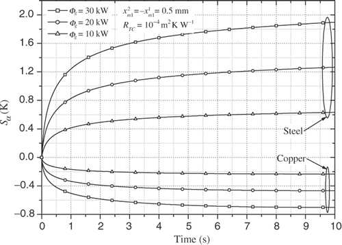
shows that Sα is monotonically increasing with φg. That was expected since according to (5e), the more significant φg is, the more a variation of α generates a significant variation of the temperature field.
represents Sα versus time and sensor location. It appears clearly that Sα decreases linearly with the distance between sensor location and interface.
Sα presents appreciable levels of value, about several Kelvin. There too, it is noted that the sensitivity related to the measurement point in copper is definitely lower (in absolute value) than that related to the measurement point in steel. But, in any case, the measurement sensitivities are largely higher than the detection threshold of the thermal sensors.
3.3. Identifiability
The problem of identifiability is significant in this application. Indeed α can be estimated only if a significant heat flux is generated at the interface. We mean by ‘significant’ that the generated heat flux causes a significant component of the heating that is generally due to several internal and external heat sources. The origin of the generated heat flux at the interface is the electrical contact resistance that draws its substance from the electric constriction phenomenon which is superimposed on the thermal constriction phenomenon. This last is superimposed on the thermal constriction phenomenon. The function of constriction, denoted f, is the same one in the two phenomenologies since electric and thermal constriction resistances, respectively, REC and RTC, are written as:
(33)
Correlation between REC and RTC is also due to the fact that the heat and electrical transport both involve the free electrons in the metal. So, at a given temperature T (K), the thermal and electrical conductivities of metals are proportional, but raising the temperature increases the thermal conductivity while decreasing the electrical conductivity. This behaviour is quantified in the Weidman–Franz law:
(34) where the constant of proportionality L is called the Lorenz number.
This electrothermal coupling can induce a certain correlation between the thermal contact resistance RTC and the partition coefficient of the generated heat flux α. This correlation is defined by a correlation coefficient denoted cc given by:
(35) where
are the terms of the 2 × 2 square matrix
Citation19.
RTC and α are detectable from the measured interfacial temperature jump they generate. The component of this temperature jump due to RTC is proportional to the three heat sources: temperature difference imposed at the boundaries , volumetric heat source P, and interfacial generated heat flux φg. On the other hand, the component of the interfacial temperature jump due to α is proportional only to the heat source φg. Consequently, one easily understands that the simultaneous estimation of RTC and α is possible provided that φg generates a significant measured heating.
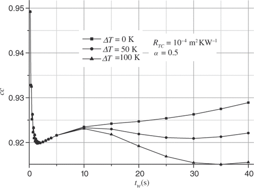
The chronology and the relative importance of the heating components due to each heat source depend on the location and the intensity of the latter. One can consider that these phenomena can influence the level of correlation between the two parameters. It is this argument, which led us to consider the behaviour of the correlation coefficient according to the extent of the estimation window that we will denote tw. We present this evolution of cc in . And for showing the chronology of the thermal events well, we considered three values of the external source . One observes in this figure that, whatever the value of ΔT, cc admits an optimal value 0.92 which always corresponds to the same temporal window covering the interval [0, topt = 1.1s]. This time interval corresponds to quite small sensitivity coefficients, however, it is in this time range that the shapes of the sensitivity coefficient curves for SR and Sα are the more different, i.e. SR and Sα curves are the less correlated. Beyond the value of tw = 7 to 8 s approximately, the curves of cc separate but the difference remains very weak. It is only beyond ΔT = 50 K that appears a second minimum slightly more favourable to the estimation (cc = 0.915).
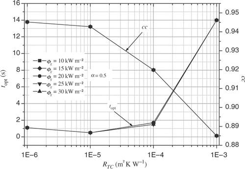
Knowing that the sensitivity coefficients SR and Sα are functions of the interface parameters RTC, α and ϕg, it is significant to emphasize the behaviour of topt according to the latter. shows that the optimal estimation window is extended more and more according to the RTC, in particular beyond RTC = 10−4 K m2 W−1. Increasing the size of the estimation window leads to a decrease of the correlation coefficient value. On the other hand, it appears that itopt and cc do not depend on φg value.
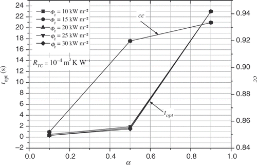
reveals that topt is monotonically increasing with α. It is clearly more sensitive to α in the domain α > 0.5. The values of topt in the domain α > 0.5 are an order of magnitude weaker than those observed in the domain α < 0.5. On the other hand cc is strongly sensitive to α in the domain α < 0.5. Here, the increase of the estimation window is accompanied by an increasingly strong correlation between the two parameters to identify. There is an opposite tendency than that observed on the variations with RTC.
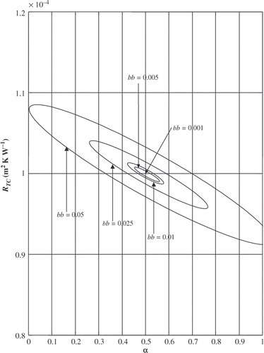
Finally, presents the confidence region of the estimation according to the signal/noise ratio. It is verified that the estimation quality is degraded according to increasing amplitude of the noise. For a white noise of average amplitude of the order of 1%, the estimation of RTC = 10−4 K m2 W−1 is accompanied by a relative inaccuracy of about 1%. That goes together with an inaccuracy on α = 0.5 of about 16%. That is related to the geometrical configuration of the J(β) contours in the (RTC, α) plane.
4. Estimation of the parameters RTC and α
The selected estimation technique is a variant of the Gauss–Newton method.
Let the vector to be estimated be denoted . The estimation method is based on the minimization of the sum of squares criterion:
(36) where
is the temperature vector calculated at time tk at the sensor locations
and
.
is the temperature measured at time tk at the same locations. Nt is the total number of measurements including total number of sensors locations.
Starting from an initial vector β0 the Gauss–Newton algorithm determines at each iteration the vector βn+1 (n ≥ 0) given by the Equation (15a):
(37) with:
(38) where Xn is the sensitivity matrix computed at iteration n. Xn is defined as a function of sensitivity vectors as:
(39) where superscripts indicate time index of measurement, and subscripts correspond to sensor locations.
The calculation of according to the Equation (15b) poses the numerical problem of the inversion of the matrix
that is poorly conditioned. This problem was regularized by the Tikhonov's procedure, by multiplying the diagonal terms of the matrix by a factor
, where
Citation20–23. The values chosen for the regularization parameter ε influence the stability of the solution. As
, the solution may exhibit oscillatory behaviour and become unstable. On the other hand, with large values of ε, the solution is damped and deviates from the exact result. So, the value of ε is chosen to ensure an optimum conditioning and to minimize the bias. ϵ ranges from 10−3 to 10−4 Citation24.
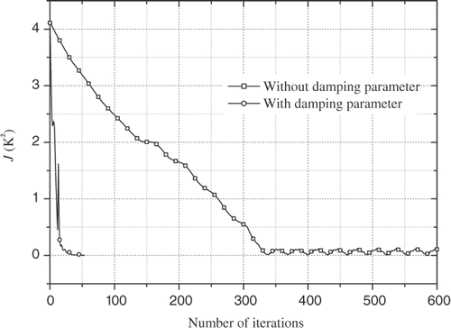
As shown in Section 3.3, the inverse heat transfer problem is ill conditioned, and especially near the initial guess used for the unknown parameters. This causes oscillations and instabilities of the solution, and mainly at the beginning of the iterative procedure. The use of a damping parameter μn scaling the term alleviates such difficulties Citation25–30. μn is defined as:
(40) μn is then gradually reduced as the iteration procedure advances to the solution of the parameter estimation problem. The coefficient ½ is obtained empirically. This refinement of the Gauss–Newton method permits the division of the iterations count by a factor of seven. illustrates that result. It represents evolution of criterion J during the iterative procedure to estimate two parameters RTC = 10−4 m2 K W−1 and α = 0.5. To test the estimation method, computed temperatures by the direct problem replaced measurements. clearly shows that without damping parameter μn, criterion J decreases slowly until iteration 350, then oscillates indefinitely. On the other hand, by using damping parameter μn defined by Equation (17), J decreases more quickly and estimation procedure converges after only 50 iterations.
5. Experimental study
In this section, we present the experimental methodology, which requires the inverse analysis developed higher. We describe the experimental device and the measurement procedure. Thereafter, we present the results of an experiment carried out six times in order to test the reliability of the methodology. We analyse the temperature recordings and the contact parameters estimation results.
5.1. Experimental device
The experimental device is presented in . We are interested in the contact interface between two metallic cylinders of the same dimensions (a) equipped with thermocouples (b). The cylinders are laid down between two water boxes (c) that are fixed at the electrodes of the power supply (d). The electrical current is provided with a regulation system. The normal force applied to the contact is also controlled. The water boxes carry water flows (e) that permit the imposition of the desired temperatures on the boundaries of the cylinders in contact. A cold box (f) accommodates the cold junctions of the thermocouples. The temperature signals are amplified (g) before their recording by means of a fast multi-channel acquisition system (h).
The theoretical aspects of the instrumentation by thermocouples in order to estimate correctly the thermal conditions at the contact interface were the subjects of a specific analysis Citation31,Citation32. The choice of the position of the two thermocouples comprising each flux-meter was based on the research of the best sensitivity-precision of measurement compromise that one wishes to give to the contact parameters estimations Citation14. We saw higher that the measurement sensitivity with respect to the RTC and to α are increasing when the values of (j = 1, 2) are decreasing. But it is necessary to avoid disturbing the thermal field near the interface by significant removals of matter (drillings) near the contact. That would induce parasitic thermal macro-constrictions. In other words, the measuring accuracy is better when the diameter of bored holes receiving the thermocouples is smaller.
Finally we drilled holes with a diameter of 0.5 mm, parallel with the bases of the cylinders. The bottom of each hole reaches the cylindrical axis of symmetry. They are located at 2 mm and 12 mm from the contact. The thermocouples of the K-type have diameter of 80 µm. The hot junctions are welded at the bottom of the holes. Thermocouples are thus parallel to the interface and follow isothermal lines. The instrumented cylinders are assembled by brazing with the water boxes and are placed between the electrodes of the power supply.
5.2. Experimental procedure
The experimental procedure consists of putting the two cylinders in contact between the two electrodes of the power supply and to apply a normal compression force F. In this case, we have chosen F = 82 daN, which corresponds to a nominal contact pressure at the interface of 2.61 MPa. The two water boxes carry water circulations at the same temperature. Once the thermal steady state is reached, we switch on the electrical current that crosses the two cylinders during 4 s. The cylinders warm up then by the Joule effect. A fast acquisition system related to the cold reference box, where all the thermocouple wires are connected, allows to record this heating during the current passage and the consecutive cooling after the cut of the current.
The electric contact resistance RTC is obtained by additional measurements Citation15. In the present experiment we consider REC = 1.5 × 10⁻⁸ Ω m2.
The temperature recordings obtained during the acquisition are filtered in order to eliminate the measurement noise of frequency 50 Hz due to the passage of the AC current in the cylinders. After treatment of the signals, one then proceeds to the estimation of the contact parameters RTC and α.
5.3. Measurements and estimations: reproducibility of temperature recordings and order of magnitude of RTC and α
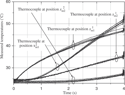
The experiment is carried out six times in order to test the reproducibility of the temperature measurements. presents the rough temperature recordings of the six experiments realized under identical conditions. The figure presents the four curves obtained from the output of each thermocouple located at the positions ,
,
and
. The beginning and the end of each signal present small disturbances corresponding to the opening and the closing of the electric circuit. These disturbances are filtered before RTC and α estimations.
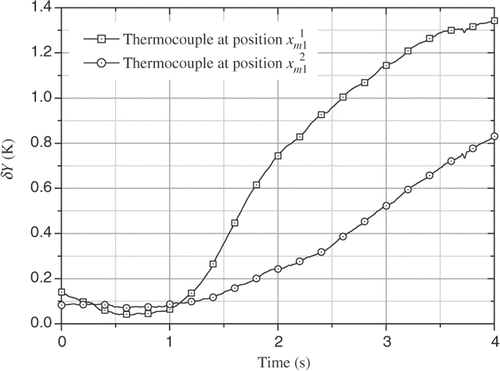
represents the dispersion curves of the measured temperatures in and
which constitute the additional information of the inverse problem. Both curves present comparable levels of value for t < 1s (0.1 K approximately), but differ beyond t = 1 s. For the two thermocouples, δY(t) curves adopt monotonically increasing evolutions and reach, at t = 4 s, maximum values equal to 1.35 K for
and 0.84 K for
. These values that, respectively, account for 6% and 3% of the local measured heating by each thermocouple do not interest us. Indeed, in accordance with the simulation results of the sensitivity study, we just consider a temporal window whose optimal size is [0, 1 s]. That offers the double advantage of having the lowest correlation level between RTC and α and of corresponding to the lowest measurements dispersion.
The post processing of the six experiments is done under the same numerical conditions. gathers the results of estimations. The values of RTC and α, their average values, as well as the dispersions that characterize them are presented. contains too the value of α given by the theoretical model Citation14.
Table 2. Estimations results.
One notes the very weak differences between the values of RTC and α estimated starting from the six tests. Posted dispersions represent only the incidences of the dispersion of the temperature measurements. The dispersion of RTC and α are, respectively, about 0.7 and 5% of the estimated average values. That shows the good reliability of the experiment.
On the other hand, if one refers to , the uncertainty calculation is not favourable to the parameter α. Indeed a measurement error of about 1% on the temperatures would imply an inaccuracy of 1% on RTC and another of 16% on α. That indicates the influence of the indirect character of measurement and especially illustrates the importance of the correlation between the two parameters observed in the calculation of sensitivities.
The estimation of RTC is in accordance with the range of usually allowed values for a steel–copper contact. In addition, the estimation of α is about equal to the value given by the theoretical model Citation14. These results confirm the reliability of the experiment and of the estimation method, and permit to validate the theoretical model of α.
6. Conclusion
The access to thermal conditions at a solid–solid contact with interfacial heat generation requires the knowledge of two contact parameters: the thermal contact resistance (RTC) and the partition coefficient of generated heat flux at the interface (α). In a previous paper, we proposed a theoretical model of α based on a microscopic approach of the electrothermal contact in steady state Citation14. In order to validate this model, we have developed an experimental methodology that allows the simultaneous estimation of both contact parameters. This methodology is based on a precise instrumentation by thermocouples and an estimation based on the minimization of a least squares (L-S) criterion using a Gauss–Newton algorithm.
The measurement principle is found on the analysis of the transient thermal response of two copper and steel cylinders in imperfect contact heated by the Joule effect.
The experimental conditions (cylinders dimensions, heating level, sensors locations) have been carefully designed in order to satisfy on one hand the one-dimensional heat transfer assumption, and on the other hand, the assumption of linear modelling equations, and thus to simplify the sensitivity analysis.
Numerical experiments have shown that both contact parameters to be estimated are highly correlated. The inverse analysis shows that choosing the adequate time interval of measurement can reduce the correlation coefficient. The optimal extent of this interval depends on the parameter values to be estimated. Thus for a given set of experimental conditions, the solution of the inverse problem is performed using an initial guess of the couple (RTC, α). This choice is based on physical considerations that take into account different experimental variables like the materials properties, the contact pressure and the interface structure. Adjusting the estimation time interval can then refine the first estimations.
The tests of reproducibility reveal that the temperature measurements present very weak dispersions. That shows the satisfactory reliability of the experiment. Consequently, the estimated values of RTC and α are weakly dispersed and are in accordance with the theoretical models of these two parameters. That confirms the temperatures measurements quality and the dependability of the estimation method. The estimations results of α allow validating the theoretical model of this parameter Citation14.
So as to check the results of this work, a new experiment is envisaged. This one consists in measuring α and RTC in steady state and in the case of heating not exceeding a few tens Kelvin. This new experimental methodology permits to estimate first RTC when the two cylinders in contact are crossed only by a heat flux (without electrical current). Then, by heating the cylinders by the Joule effect, and knowing the RTC value, it is easy to deduce α starting from the measurement of the temperature jump at the interface.
References
- Holm, R, 1967. Electric Contacts. Theory and application. Berlin: Springer-Verlag; 1967.
- 1995. Fechant, L, ed. Le Contact Électrique: Phénomène Physique et Matériaux. Paris: Hermes, Collection SEE; 1995.
- Mazo, L, Cassagne, B, Badie-Levet, D, and Bardon, JP, 1978. Etude des conditions de liaison thermique dans le cas du frottement sec métal-plastique, Revue Générale de Thermique. 204 (1978), pp. 919–933.
- Mazo, L, 1977. Contribution à l’étude thermocinétique du frottement métal-plastique. Thèse de doctorat, Université de Nantes; 1977.
- Badie-Levet, D, 1984. Champs de température engendrés par le frottement de deux anneaux concentriques en rotation relative, dans le cas d’une condition de contact imparfait, Revue Générale de Thermique 275 (1984), pp. 671–679.
- Bardon, JP, 1994. Bases Physiques des conditions de contact thermique imparfait entre deux milieux en glissement relatif, Revue Générale de Thermique 386 (1994), pp. 85–91.
- Chantrenne, P, and Raynaud, M, 1997. A microscopic thermal model for dry sliding contact, Int. J. Heat Mass Transf. 40 (1997), pp. 1083–1094.
- Laraqi, N, 1992. Température de contact et coefficient de partage du flux généré par frottement sec entre deux solides. Approche nouvelle de la génération de flux, Int. J. Heat Mass Transf. 35 (1992), pp. 3131–3139.
- Bauzin, J-G, and Laraqi, N, Experimental determination of the thermal contact resistance and the local heat partition coefficient at the interface of two solids in dry friction. Presented at Proceedings of 12th IHTC. Grenoble, 27–32, 2002.
- Bauzin, J-G, and Laraqi, N, Estimation of thermal contact parameters at the interface between two sliding solids. Presented at Proceedings of Eurotherm 68. Poitiers, 2001.
- Bauzin, JG, and Laraqi, N, 2004. Simultaneous estimation of frictional heat flux and two thermal contact parameters for sliding solids, Numer. Heat Transf. 45 (2004), pp. 313–328.
- Alilat, N, Baïri, A, and Laraqi, N, 2004. Three-dimensional calculation of temperature in a rotating disk subjected to an eccentric circular heat source and surface cooling, Numer. Heat Transf. 46 (2004), pp. 167–180.
- Laraqi, N, 2003. An exact explicit analytical solution for steady-state temperature of a half space subjected to a circular moving heat source, ASME J. Tribol. 125 (2003), pp. 859–862.
- Meur, GLe, 2002. Etude de la condition de liaison thermique à une interface de contact solide–solide siège d’une dissipation par effet Joule: Application au soudage par résistance. Thèse de Doctorat, Université de Nantes; 2002.
- Thieblemont, E, 1992. Modélisation du soudage par résistance par point. Thèse de doctorat, Institut Polytechnique de Lorraine; 1992.
- Brady, GS, and Clauser, HR, 1979. Materials Handbook. New York: McGraw & Hill; 1979.
- Steiner, R, 1990. ASM Handbook: Properties and Selection: Irons, Steels, and High Performance Alloys. Vol. 1. Materials Park, Ohio, USA: ASM International; 1990.
- Özisik, MN, and Orlande, HRB, 2000. Inverse Heat Transfer.. New York: Taylor & Francis; 2000.
- Kenney, JF, and Keeping, ES, 1962. "Linear regression and correlation". In: Nostrand, Van, ed. in Mathematics of Statistics, Pt. 1. NJ: Princeton; 1962, Chapter 15.
- Tikhonov, AN, and Arsenin, VY, 1977. Solution of Ill-posed Problems. Washington DC: Winston & Sons; 1977.
- Tikhonov, AN, 1963. Solution of incorrectly posed problems and the regularization method, Soviet Math. Dokl. 4 (1963), pp. 1035–1038.
- Tikhonov, AN, 1963. Regularization of incorrectly posed problems, Soviet Math. Dokl. 4 (1963), pp. 1624–1627.
- Tikhonov, AN, 1975. Inverse problems in heat conduction, J. Eng. Phys. 29 (1975), pp. 816–820.
- Huang, CH, and Özisik, MN, 1991. Optimal regularization method to determine the strength of a plane surface heat source, Int. J. Heat Fluid Flow 12 (1991), pp. 173–178.
- Levenberg, K, 1944. A method for the solution of certain non-linear problem in least squares, Quart. Appl. Math. 2 (1944), pp. 164–168.
- Marquardt, DW, 1963. An algorithm for least squares estimation of non-linear parameters, J. Soc. Ind. Appl. Math. 11 (1963), pp. 431–441.
- Bard, YB, 1974. Non-linear Parameter Estimation. New York: Academic Press; 1974.
- Beck, JV, and Arnold, KJ, 1977. Parameter Estimation in Engineering and Science. New York: Wiley; 1977.
- Dennis, J, and Schnabel, R, 1983. Numerical Methods for Unconstrained Optimization and Non-linear Equations. New Jersey: Prentice Hall; 1983.
- Özisik, MN, 1993. Heat Conduction. New York: Wiley; 1993.
- Bourouga, B, Goizet, V, and Bardon, JP, 2000. Les aspects théoriques régissant l'instrumentation d'un capteur thermique pariétal à faible inertie, Int. J. Therm. Sci. 39 (2000), pp. 96–109.
- Sorin, A, Bourouga, B, Gilles, J, and Dupont, A, 2002. Etude Numérique du caractère intrusif de l’instrumentation pariétale par thermocouple. Vittel: Congrès Annuel de la SFT; 2002.
