Abstract
The specific contribution made by this work in the area of geared five-bar path generation is the formulation of a non-linear optimization problem that includes elastic deflection, static torque and buckling constraints. Using this model, geared five-bar path generators are also synthesized with respect to static torque, deflection constraints and buckling constraints for a given rigid-body load.
1. Introduction
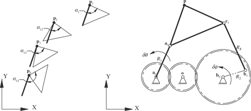
Mechanism synthesis is an inverse engineering field in which specific mechanism linkage dimensions are calculated to achieve or approximate a series of user-prescribed mechanism output parameters. In path generation (a subcategory of mechanism synthesis), the objective is to calculate the mechanism linkage dimensions required to achieve or approximate a set of prescribed rigid-body path points. This mechanism design objective is particularly useful when the rigid-body must achieve a specific path for effective operation (e.g. specific tool paths for accurate fabrication operations). In , four sets of prescribed rigid-body path generation parameters are defined by variables p and α (prescribed path generation model input) and the model output are the calculated coordinates of the five-bar mechanism moving pivot variables a1 and c1 and scalar link lengths R1 and R3 required to approximate the prescribed path generation parameters. A conventional geared five-bar path generation model Citation1 is presented in the next section.
Figure 1. Prescribed rigid-body path generation parameters and calculated geared five-bar mechanism.
Path generation for planar five-bar mechanisms is a fairly-established field. Recent contributions include the works of Balli and Chand Citation2,Citation3 that introduce a complex number method for the synthesis of a planar five-bar motion and path generator with prescribed timing and a method to synthesize a planar five-bar mechanism of variable topology type with transmission angle control. Mundoa et al. Citation4 performed an optimization of the five-bar linkage with non-circular gears as a mechanism capable of precisely moving a coupler point along a prescribed trajectory. Zhou and Ting Citation5 analysed singularity-free path generation capability of five-bar slider-crank parallel manipulators. Ge and Chen Citation6 introduced a software-based approach for the atlas method on path synthesis of geared five-bar mechanisms.
Although a substantial number of contributions have been made regarding planar five-bar path generation, the concept of including structural conditions in mechanism synthesis is not nearly as established. With the exception of Huang and Roth Citation7 whose work includes analytical synthesis models for planar four-bar mechanisms with a prescribed rigid-body load, most other works that investigate the structural behaviour of mechanisms under load do not consider the structural behaviour in the context of mechanism synthesis. The works of Dado Citation8, Venanzi et al. Citation9, Sönmez Citation10, Plaut et al. Citation11 and Sriram and Mruthyunjaya Citation12 do consider flexible links and/or buckling in mechanism design, but they consider the design of compliant mechanisms as opposed to classical linkage-based mechanisms.
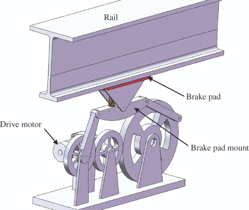
One application where a planar five-bar mechanism is subjected to rigid-body loads in static positions is braking. illustrates a five-bar traveller braking mechanism. This mechanism is used in suspension bridge travellers (a moving platform to carry personnel and equipment beneath suspension bridges for inspection and maintenance) when calliper brakes are not practical. When the brake is applied due to a driver torque (supplied by the drive motor in ), a reaction load is applied to the brake pad and subsequently the rigid-body. Other applications where a five-bar mechanism would be subjected to rigid-body loads in static or quasi-static positions include pressing, stamping and boring. Although the work of Huang and Roth Citation7 does consider planar mechanisms in static positions with rigid-body loads, this work does not consider link deflection and buckling due to the rigid-body loads-structural responses that will compromise the structural integrity of the mechanism and subsequently the accuracy of the precision points achieved.
The specific contribution made by this work regarding path generation with structural conditions for geared five-bar mechanism is the formulation of a non-linear optimization problem that includes elastic deflection, static torque and buckling constraints. Being a non-linear optimization problem, an indefinite number of prescribed rigid-body path points can be incorporated. As demonstrated in the included example, using the non-linear optimization problem formulated in this work, a geared five-bar mechanism is synthesized to approximate a set of prescribed rigid-body path points and also satisfy specified elastic deflection, static torque and buckling conditions for a given rigid-body load.
2. Geared five-bar path generation
Equations (Equation1–3(1) ) encompass a conventional geared five-bar motion generation model Citation1.
(1)
(2)
(3)
These equations are ‘constant length’ constraints and ensure the fixed lengths of links a0a1, b0b1 and b1c1 throughout the prescribed rigid-body displacements. Variables and
in Equations (Equation1–3
(1) ) are the prescribed squared scalar lengths of links a0a1, b0b1 and b1c1 respectively. Variables R1, R2 and R3 are interchangeable with
,
and
.
(4)
(5)
Equation (Equation4(4) ) is a rigid-body planar displacement matrix. Equation (Equation5
(5) ) is the angular displacement matrix for link b0b1 where
and (δφ)1i = k(δθ)1i. Variable k represents the gear ratio of the gear train joining grounded links a0a1 and b0b1. From this conventional planar five-bar path generator model, 12 of the 13 unknown five-bar mechanism variables a0, a1 R1, b0, b1, R2, c1 and R3 are calculated with one arbitrary choice of parameter for five sets of prescribed rigid-body path generation parameters (where a0 = [a0x, a0y, 1], a1 = [a1x, a1y, 1], b0 = [b0x, b0y, 1], b1 = [b1x, b1y, 1] and c1 = [c1x, c1y, 1]). If R1, R2 and R3 are replaced with a0, a1, b0, b1 and c1, then nine of the 10 unknown five-bar mechanism variables are calculated.
3. Geared five-bar mechanism under rigid-body load
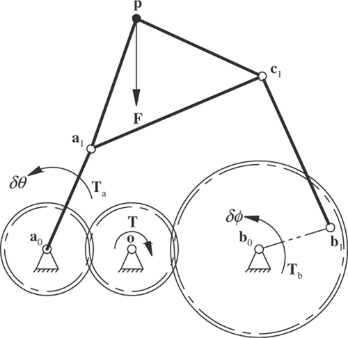
In this work, the moving pivot b1 is affixed to the gear centred at the fixed pivot b0 (). The moving pivot does not extend beyond the pitch circle. Also, the gears are considered rigid and subsequently not subject to deflection due to rigid-body loading.
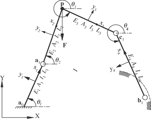
illustrates a statically-loaded geared five-bar mechanism deflection model diagram. In this work, link a0a1 is only connected to its corresponding gear at a0. Because of this condition, link a0a1 is illustrated in as having a single connection to the ground. A load {F} is applied to the mechanism (in this work, at rigid-body point p). An analytical model to calculate the deflections {U} at any element node on this mechanism is formulated using Equation (Equation6(6) ) where the 15 × 15 global stiffness matrix [Kgobal] for the mechanism is composed of Equation (Equation7
(7) )–the element stiffness matrix for each mechanism link. The element stiffness matrix for link a0a1 and the rigid-body (link a1pc1) is given by Equation (Equation8
(8) ) Citation13. Because link b1c1 is a two-force member (and therefore under columnar loading only), its element stiffness matrix [kaxial] is given by Equation (Equation9
(9) ) Citation13. Equation (Equation10
(10) ) transforms each local element coordinate frame to the global coordinate frame by rotating each element node by the associated element angle θj Citation13.
In variables Ej, Aj, Ij and Lj (where j = 1, 2, 3, 4) are the modulus of elasticity, cross-sectional area, moment of inertia and length of each link, respectively. Because link a1pc1 is to be a uniform rigid-body in this study, E2 = E3, A2 = A3, I2 = I3 and its modulus of elasticity is one million times higher than those of link a0a1 and link b1c1 (specifying such a large modulus makes the coupler link virtually rigid). The angular orientation of each link (using the positive x-axis as reference) is denoted by angle θj (where j = 1, 2, 3, 4). These angles are used in the transformation matrix (Equation (Equation10
(10) )).
(6)
(7)
(8)
(9)
(10)
4. Driver static torque constraint
With an external load F acting on the rigid-body of the geared five-bar mechanism, a torque T applied to the driver (which is the intermediate gear in this work) achieves static equilibrium. In , the load F is applied to rigid-body at point p. To formulate the driver static torque constraint, the moment condition ΣM = 0 () is taken about the fixed pivot a1. The equilibrium moments equation about the fixed pivot a1 is
(11) where
(12)
The reaction load Rc is a real number that varies with the mechanism position. Equation (Equation12(12) ) is the product of the columnar load along link b1c1 (Rc) and the unit vector for link b1c1. Solving for Rc from Equations (Equation11
(11) ) and (Equation12
(12) ) and substituting it in Equation (Equation11
(11) ) we get Rc1 as
(13)
Figure 5. Geared five-bar mechanism link a0a1 (a) rigid-body (b) and link b0b1 (c) in static equilibrium with reaction loads Ra1 and Rc1.
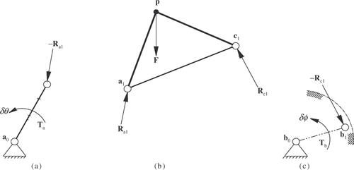
The resulting equilibrium of force equation for the rigid-body in is
(14)
Substituting Equation (Equation13(13) ) into Equation (Equation14
(14) ) and solving for Ra1 produces
(15)
With the rigid-body reaction load Equations (Equation13(13) ) and (Equation15
(15) ) formulated, torque equations for the gears about a0 and b0 are formulated next. The moment condition ΣM = 0 is taken about the fixed pivot a0 for link a0a1 in . The resulting equilibrium equation of the moments about a0 is
(16)
Substituting Equation (Equation15(15) ) into Equation (Equation16
(16) ) and solving for torque Ta produces
(17)
The moment condition ΣM = 0 is now taken about the fixed pivot b0 for link b0b1 in . The resulting equilibrium equation of the moments about b0 is
(18)
Substituting Equation (Equation13(13) ) into Equation (Equation18
(18) ) and solving for torque Tb produces
(19)
In Equations (Equation17(17) ) and (Equation19
(19) )
As mentioned earlier, the intermediate gear is the designated driver in this work. Neglecting power loss, the static equilibrium driver torque is
(20) where
. Variables ra, rb and r are the pitch radii of the gears centred at a0, b0, and o, respectively (). Equation (Equation20
(20) ) calculates the five-bar mechanism driver static torque for a given rigid-body load. Expressing Equation (Equation20
(20) ) as an inequality constraint to limit the maximum driver static torque for N prescribed rigid-body path points yields
(21)
5. Link buckling and elastic deflection constraints
As previously discussed, link b1c1 is under columnar loading only because it is a two-force member. The Euler formula for critical buckling load for a column with pinned ends Citation14 is
(22) where variables E, I and L are the modulus of elasticity, moment of inertia and effective column length, respectively. The equation for scalar columnar load Rc in link b1c1 is formulated by substituting Equation (Equation12
(12) ) into Equation (Equation11
(11) ) and solving for Rc. Expressing Equation (Equation3
(3) ) as an inequality constraint to prevent link b1c1 buckling for N the prescribed rigid-body path points yields
(23) where the right-side term is L2 in Equation (Equation22
(22) ). Because the right-side term in inequality constraint (23) is the squared scalar length of link b1c1, this link is constrained to a length that is less than its buckling length.
Unlike link b1c1, link a0a1 is not a two-force member and subsequently not under columnar loading only. Because this link is held in static equilibrium by a torque about a0, there is also a transverse load component acting on link a0a1. In this work, the buckling of link a0a1 is not explicitly considered because the link stiffness required to limit transverse deflection is generally sufficient in avoiding link buckling (especially as the maximum permissible transverse deflection becomes smaller). As shown in and , this link is a fixed-end cantilevered beam under a load with a transverse component. Because the constraint and loading conditions on link a0a1 make link deflection a common occurrence, constraining the deflection of link a0a1 is critical.
The Euler formula for the deflection of a fixed-end cantilevered beam Citation14 is
(24) where variables P, L, E and I are the free-end transverse load, beam length, modulus of elasticity and moment of inertia, respectively. Equation (Equation15
(15) ) is the total load on the moving pivot a1. The transverse component of this load is
(25)
Expressing Equation (Equation1(1) ) as an inequality constraint to limit crank deflection for N the prescribed rigid-body path points yields
(26) where the right-side term is L2 in Equation (Equation24
(24) ). Because the right-side term in inequality constraint (26) is the squared scalar length of link a0a1, this link is constrained to a length that produces a maximum static deflection that is less than the specified maximum static deflection.
6. Path generation non-linear optimization problem
Formulating Equations (Equation1(1) ) and (Equation3
(3) ) into a single objective function that accommodates an indefinite number of N sets of prescribed path generation parameters to be minimized yields
(27) where
. Equation (Equation27
(27) ) and inequality constraints (21), (23) and (26) constitute a non-linear optimization problem from which mechanism solutions that approximate the prescribed rigid-body path points and satisfy maximum static torque, maximum elastic deflection and buckling conditions are calculated.
The algorithm employed for solving this non-linear optimization problem (a non-linear constraints problem) is sequential quadratic programming (SQP) which uses quasi-Newton approach to solve its quadratic programming (QP) subproblem and line search approach to determine iteration step. The merit function used by Han Citation15 and Powell Citation16 is used in the following form:
(28) where
represents each inequality constraint, m is the total number of inequality constraints and the inequality constraint penalty parameter is
(29)
The value of r for successive minimizations can be found as
(30) where IR at the start and is incremented by 1 after each successive suboptimum is found. The factor FAC can be set arbitrarily although 10 is suggested for normal use Citation1. In Equation (Equation30
(30) ) l is the iteration index for calculating the penalty parameter
for each inequality constraint (l = 0, 1, 2, 3, …). The Lagrange multiplier, which is the rate of the change of the objective function being optimized with respect to the constraint variables, is
(31)
After specifying initial guesses for the unknown variables in the non-linear optimization problem (X), the following SQP steps were employed to calculate the unknown variables:
| 1. | calculate | ||||
| 2. | solve Equation (Equation28 | ||||
| 3. | calculate | ||||
| 4. | repeat step 2 with newly-calculated | ||||
Steps 2–4 constitute a loop that is repeated until the penalty term in Equation (Equation28(28) ),
is less than a specified penalty term residual
(which is 0.001 for the example in this work).
The SQP algorithm does not guarantee global optimization. The quality of the initial guesses could determine whether or not the algorithm converges (or if it does converge, to what values). The authors employed computer-aided drafting software to assist in specifying the initial guesses. Drafting and superimposing the prescribed rigid-body precision positions in 2-D space enabled the authors to determine likely locations (and subsequently likely initial guesses) for the fixed and moving pivots.
Rather than codifying the SQP algorithm as a stand-alone program, the authors used Mathcad–a commercial mathematical analysis software with SQP built in. Other commercial mathematical analysis software such as Mathematica and Matlab also include non-linear optimization problem solvers like SQP. The non-linear optimization problem formulated and presented in this work ran efficiently in Mathcad–having run times that measured in seconds.
7. Example
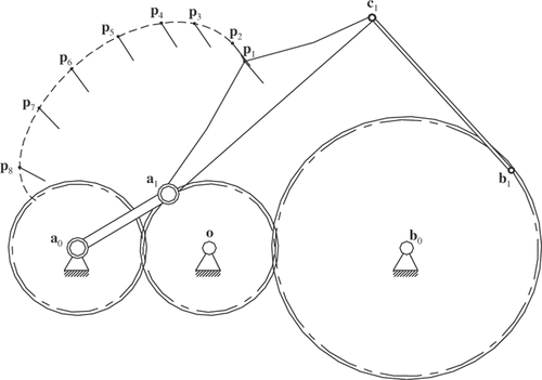
includes the x- and y-coordinates (in inches) of eight prescribed rigid-body path points and displacement angles (therefore N = 8 in Equation (Equation27(27) )). This is nearly twice the maximum number of prescribed path points available with the conventional path generation method included in this work Citation1. The maximum allowed driver torque is τmax = 6350 in-lbs and the rigid-body load at p is F = (0, −1000, 0)T lbs with gear pitch radii ra, rb and r of 5, 10 and 5 inches, respectively. Link a0a1 and b1c1 shall be constructed of solid rectangular steel tubing (E = 29 × 106 psi) of ¾ in (deep) × ½ in (wide) and 9/32 in × ¼ in, respectively. This example assumes that the links will be constructed of ‘off-the shelf’ steel bars of standard sizes (as opposed to custom made bars where the moment of inertia could be a design variable). For each prescribed rigid-body position, the maximum deflection of link a0a1 shall not exceed 0.31 inch and preventing the buckling of link b1c1 is critical.
Table 1. Prescribed rigid-body path generation parameters.
Using the path generation non-linear optimization problem (where N = 8 results in m = 24 in Equation (Equation28(28) )) with prescribed values (in inches) of a0 = (0, 0), b0 = (25, 0), b1 = 33, 6) and R2 = 10, and initial guesses (in inches) of a1 = (10, 5), R1 = 10, c1 = (20, 20) and R3 = 15 the calculated solution is a1 = (6.9002, 4.2070), R1 = 8.0815, c1 = 22.3731, 17.9572) and R3 = 15.9274. includes the resulting static torque and deflection of the crank link as well as the resulting columnar loads for link b1c1. Using Equation (Equation22
(22) ), the calculated critical buckling load for link b1c1 for the synthesized mechanism is 411 pounds. The length required to satisfy the transverse deflection condition for link a0a1 also results in safe buckling load of 78,612 pounds.
Table 2. Crank static torques, deflections and follower link columnar loads.
Because links a0a1 and b1c1 are flexible, the deflections of these links simultaneously compromise the accuracy of the rigid-body path points achieved by the synthesized mechanism. includes the rigid-body path points (and corresponding angles for link a0a1) calculated after incorporating the parameters of the synthesized mechanism in the geared five-bar mechanism deflection model in Section 3. also includes the scalar difference between the achieved and prescribed rigid-body path points. illustrates the synthesized geared five-bar path generator. As illustrated in this figure, the moving pivot b1 is on the pitch circle of the gear centred at the fixed pivot b0.
Table 3. Rigid-body path points achieved by synthesized elastic geared five-bar mechanism, crank angle and precision point scalar structural error |pPrescribed − pAchieved|.
Using the conventional path generation model with initial guesses (in inches) of a0 = (0, 0), a1 = (10, 5), b0 = (25, 0), b1 = (33, 6) and c1 = (20, 20), the calculated solution is a0 = (5.1549, 3.6340), a1 = (11.6178, 8.0042), b0 = (9.5497, −0.3464), b1 = (31.2905, 4.7351, and c1 = (10.9531, 11.5631). This five-bar mechanism solution has a b1c1 length of R3 = 21.4530 which is 34.69% longer (and more susceptible to buckling with a critical buckling load of just 227 pounds).
8. Discussion
The non-linear optimization problem presented in this work does not consider the load contribution made by the link masses because the five-bar mechanism is assumed to be static and the rigid-body loads considered are assumed to far exceed the link body forces. Planar five-bar applications as such are best suited for this methodology. Equations (Equation17(17) ), (Equation19
(19) ) and subsequently (20) become invalid when the pivots a1, b1 and c1 are collinear. Such a state is possible when the five-bar mechanism reaches a ‘lock-up’ or binding position. When pivots a1, b1 and c1 are collinear, the denominator in Equations (Equation17
(17) ) and (Equation19
(19) ) become zero (making these equations and subsequent driver torque constraint invalid). The specific geared five-bar mechanism design considered in this work is one where a0a1 is a link attached to the gear centred at a0 and b1 is a moving pivot on the gear centred at b0. If the moving pivot a1 is to be mounted directly to the gear centred at a0, the deflection constraint (Equation (Equation26
(26) )) can be excluded from the non-linear optimization problem since the gears are considered rigid. Different types of gear-to-link attachments change the mechanism elastic behaviour (Equation (Equation5
(5) )) and subsequent deflection constraints (Equation (Equation26
(26) )). The mathematical analysis software MathCAD was used to codify and solve the formulated goal program.
9. Conclusion
A non-linear optimization problem to synthesize geared five-bar path generators that also includes static torque, elastic deflection and buckling constraints was formulated and demonstrated in this work. Given a set of rigid-body path points, a rigid-body load, maximum driver torque and deflection values and Young's modulus and moment of inertia data for links a0a1 and b1c1, a geared five-bar mechanism was synthesized using the non-linear optimization problem formulated in this work.
References
- Suh, CH, and Radcliffe, CW, 1978. Kinematics and Mechanism Design. New York: John Wiley and Sons; 1978.
- Balli, SS, and Chand, S, 2002. Five-bar motion and path generators with variable topology for motion between extreme positions, Mech. Mach. Theory 37 (11) (2002), pp. 1435–1445.
- Balli, SS, and Chand, S, 2004. Synthesis of a five-bar mechanism for variable topology type with transmission angle control, J. Mech. Des. 126 (1) (2004), pp. 128–134.
- Mundoa, D, Gattia, G, and Dooner, DB, 2009. Optimized five-bar linkages with non-circular gears for exact path generation, Mech. Mach. Theory 44 (4) (2009), pp. 751–760.
- Zhou, H, and Ting, K-L, 2005. Path generation with singularity avoidance for five-bar slider-crank parallel manipulators, Mech. Mach. Theory 40 (3) (2005), pp. 371–384.
- Ge, W, and Chen, Z, 1999. Study of geared five-bar curves based on computer mechanism simulation with variable parameters, Mech. Sci. Technol. 18 (3) (1999), pp. 435–437.
- Huang, C, and Roth, B, 1993. Roth, Dimensional synthesis of closed-loop linkages to match force and position specifications, J. Mech. Des. 115 (2) (1993), pp. 194–198.
- Dado, MHF, 2005. Limit position synthesis and analysis of compliant 4-bar mechanism with specified energy levels using parametric pseudo-rigid-body model, Mech. Mach. Theory 40 (1) (2005), pp. 977–992.
- Venanzi, S, Giesen, P, and Parenti-Castelli, V, 2005. A novel technique for position analysis of planar complaint mechanisms, Mech. Mach. Theory 40 (11) (2005), pp. 1224–1239.
- Sönmez, Ü, 2007. Introduction to compliant long dwell mechanism designs using buckling beams and arcs, J. Mech. Des. 129 (8) (2007), pp. 831–843.
- Plaut, RH, Alloway, LA, and Virgin, LN, 2003. A nonlinear oscillations of a buckled mechanism used as a vibration isolator. Presented at Proceedings of the IUTAM Symposium.
- Sriram, BR, and Mruthyunjaya, TS, 1995. Synthesis of path generating flexible-link mechanisms, Comput. Struct. 56 (4) (1995), pp. 657–666.
- Moaveni, S, 1999. Finite Element Analysis Theory and Application with ANSYS. Englewood Cliffs: Prentice-Hall; 1999.
- Pilkey, WD, 1994. Formulas for Stress, Strain and Structural Matrices. New York: John Wiley and Sons Inc.; 1994.
- Han, SP, 1977. A globally convergent method for nonlinear programming, J. Optim. Theory Appl. 22, (1977), p. 297.
- Powell, MJD, 1978. Watson, GA, ed. A fast algorithm for nonlinearly constrained optimization calculations, in Numerical Analysis, Lecture Notes in Mathematics. Vol. 630. Berlin: Springer Verlag; 1978. pp. 144–157.
