Abstract
Biomedical imaging has developed into the level of molecular imaging. Bioluminescence tomography (BLT), as an optical imaging modality, is a rapidly developing new and promising field. So far, much of the theoretical analysis of BLT is based on a diffusion approximation equation for media with constant refractive index. In this article, we study the BLT problem for media with spatially varying refractive index. We introduce a general framework with Tikhonov regularization for this purpose, present its well-posedness and establish the error bounds for its numerical solution by the finite element method. Numerical results are reported on simulations of the BLT problem for media with spatially varying refractive index.
1. Introduction
With the development of science and technology, these years have witnessed the rapid progress in biomedical imaging. Bioluminescent imaging (BLI), as one of the optical imaging modalities, has its own advantages over traditional imaging methods such as computed tomography (CT), positron emission tomography (PET) Citation1,Citation2, magnetic resonance imaging (MRI) Citation3,Citation4 as well as their combinations. For instance, compared to PET and MRI, BLI is low in cost. It is particularly attractive for in vivo applications because no external excitation source is needed, and thus background noise is low while sensitivity is high. For in vivo studies in a big biological object such as human body, BLI is limited to superficial sites owing to the absorption and scattering properties of tissue to light and in this case, PET and MRI are preferred modalities Citation5.
Table 1. Error  for different parameter r.
Bioluminescence tomography (BLT) is a promising BLI because of the possibility of revealing molecular and cellular activity in real time Citation6,Citation7. Over the past several years, numerous articles have been devoted to the theoretical analysis and numerical simulations of BLT, (see e.g. Citation8–16 and references therein). The main objective of BLT is to determine the photon density distribution within small-animals or on the surface of some organs from the light measurement on the boundary. With BLT, a bioluminescent source distribution inside a living small animal can be located and quantified in 3D. Because the transport of light in any entity is subject to both absorption and scattering, the accurate representation of the photon transport in a biological tissue is required. The first step of BLT is to determine the optical properties of tissue and this is the issue of a diffuse optical tomography (DOT) problem. In general, the bioluminescent photon propagation in a tissue can be described accurately by either the radiative transfer equation (RTE) or the Monte Carlo model (MCM) Citation17. However, at the moment, neither is computationally feasible. Usually a diffusion approximation of the RTE is employed when the wavelength of light is in the range of around or bigger than 600 nm Citation18.
In the literature, the BLT is mostly studied based on a diffusion approximation equation to the RTE with constant refractive index of media. In this work, we consider the BLT problem for media with spatially varying refractive index. Consideration of media with spatially inhomogeneous refractive index can be found in Citation19–25 and Citation26,Citation27, the DOT problem for such media is studied.
Let Ω ⊂ ℝd be a non-empty, open and bounded set with a Lipschitz boundary Γ ≜ ∂Ω and Sd−1 the unit sphere in ℝd. In applications, d = 3. With the diffusion approximation, our BLT problem in spatially varying refractive index media consisting of determining a source function S so that the solution of the following boundary-value problem (BVP):
(1)
(2) satisfies the measurement condition
(3) Here, Ω0 and Γ0 are measurable subsets of Ω and Γ, respectively, both with a positive measure. The symbol χΩ0 stands for the characteristic function of Ω0 which takes on the value 1 in Ω0 and 0 in Ω∖Ω0. The coefficient
, μa and
are the absorption and reduced scattering coefficients, and n is the refractive index. We denote ∂ν· for the outward normal derivative on Γ. The measured light flux g on Γ0 is an element in space L2(Γ0). In applications, it is unrealistic to have measurement on the entire boundary. In this article, we focus on the situation where Γ0 is a proper subset of Γ.
As in Citation12, we can show that the pointwise formulation (1)–(3) of the BLT problem is ill-posed. In this article, the BLT problem is studied through a Tikhonov regularization.
We will need some function spaces. For a set G as Ω, Ω0 or Γ etc., we denote by W m,s(G) the standard Sobolev spaces of degree s and order m with norm ‖ · ‖m,s,G, and rewrite them as Ls(G) when m = 0. Particularly, Hm(G) represents W m,2(G) with corresponding inner product (·, ·)m,G, norm ‖ · ‖m,G and seminorm | · |m,G. Moreover, denote L2(Ω0) by Q. We further denote by c a constant which may have different value in different place.
The structure of this article is as follows. In the next section, we study the BLT problem with a Tikhonov regularization. We address the well-posedness of the regularized BLT problem and explore the limiting behaviours as regularization parameter tends to zero and infinity. In Section 3, we use the finite element method to approximate the regularized BLT problem and obtain some error estimates. We present some numerical examples in the last section.
2. A formulation for BLT with spatially varying refractive index media
By a standard process, we obtain the following weak formulation of the BVP (1)–(2):
(4) where the bilinear form
(5) Let Γ1 = Γ\Γ0. Since the measurement (3) is available on a proper subset of Γ only, we have |Γ1| > 0. Define an inner product [·, ·] and the corresponding norm ||| · ||| over H1(Ω) as follows:
It is well-known that the norm ||| · ||| defined above is equivalent to the norm ‖ · ‖1,Ω.
We will make the following assumption throughout this article:
Assumption (A) Let 0 < b1 ≤ D ≤ c1, μa > 0, ‖μa‖0,∞ ≤ c2, n ∈ W1,∞(Ω), , ‖v‖0,Ω ≤ c4|||v|||, and min{b1, 1/2} > c1c3c4.
Under Assumption (A), it is shown in Citation26 that for each S ∈ Q, the problem (4) admits a unique and stable solution u ∈ H1(Ω).
We comment that it is possible to weaken Assumption (A). In applications, the index function n is nearly piecewise constant, i.e. it is piecewise constant in most parts of Ω except in a small neighbourhood of the interfaces of the sub-regions. In other words, there is a small number ϵ > 0 such that for a subset Ωϵ of Ω with |Ωϵ| ≤ ϵ, ∇n = 0 in . Consider the case of one dimension, d = 1. By a Sobolev embedding theorem (Citation28), there is a constant c1 such that
(6)
Assumption (B) For b1, c1, c3, c4 and given as in Assumption (A) and (6),
.
Proposition 2.1
In the case d = 1, under Assumption (B), for each S ∈ Q, the problem (4) admits a unique solution u ∈ H1(Ω) such that
(7) for some constant c > 0, which is independent of S but may depend on the parameters Ω, D, n and μa.
Proof
We apply the Lax–Milgram lemma Citation28; the only major task is to prove the coercivity of the bilinear form a1(·, ·). By using the Hölder inequality, (6) and Schwarz' inequality, we have
(8) Hence, from Schwarz' inequality together with (8), and by noticing μa ≥ 0 in Ω, we have
(9) Therefore, we attain the coercivity of the bilinear form a1(·, ·).▪
We note that Assumption (B) is weaker than Assumption (A) for small ϵ. More delicate arguments are needed to weaken the conditions on data for the coercivity in two/three dimension spaces.
Since the BLT problem in the pointwise form is ill-posed, we will study the BLT problem through a Tikhonov regularization Citation29–31. We shall only consider the case where the refractive index is constant near the domain boundary. Consequently, the boundary condition (2) reduces to
(10)
Combine (3) and the boundary condition (10) to get
(11)
From (3), we obtain another mixed boundary condition
(12)
We form two boundary value problems: Equation (1) with boundary condition (10) and Equation (1) with boundary condition (12). We then try to minimize the differences between the solutions of these problems with 2 g on the boundary Γ0. In addition to a1(·, ·) defined in (5), let
For any T ∈ Q, denote by u1 = u1(T), u2 = u2(T) ∈ H1(Ω) the corresponding weak solutions:
(13)
(14) Under Assumption (A), both problems are uniquely solvable. Moreover, we have the bound
(15)
For r ∈ [0, 1] and α ≥ 0, we introduce the following cost functional:
(16)
Then we define a general regularized BLT problem as follows.
Problem 2.2
Find Sr,α ∈ Qad such that
(17) where Qad is a convex closed subset of the space Q.
We comment that here we have introduced a family of regularized BLT problems, depending on a parameter r ∈ [0, 1]. The conventional choice for solving the BLT problem is r = 1. However, the numerical results in the final section suggest that a proper choice of the parameter r leads to an improvement in the reconstruction accuracy compared to the conventional choice, with only a slight increase in the computational effort since the stiffness matrix and the load vector in the finite element solution of the problem (13) can be used in constructing the finite element system for the problem (14).
By extending the arguments used in Citation10,Citation12, we can show the following main properties of Problem 2.2.
Proposition 2.3
For any α > 0 and r ∈ [0, 1], Problem 2.2 has a unique solution Sr,α ∈ Qad which can be characterized by a variational inequality
(18)
When Qad is a subspace of Q, the inequality reduces to a variational equality for any T ∈ Qad
The solution Sr,α depends continuously on the measurement g ∈ L2(Γ0), the regularized parameter α > 0, coefficients D ∈ L∞(Ω), n ∈ W1,∞(Ω) and μa ∈ L∞(Ω).
Assume that 0 ∈ Qad. Then ‖Sr,α‖0,Ω0 → 0 as α → ∞.
Assume taht 𝒮r ⊂ Qad, the solution set of Problem 2.2 for α = 0, is nonempty. Then, Sr,α → Sr,* as α → 0+, where Sr,* ∈ 𝒮r satisfies
We also have the following result.
Proposition 2.4
Let α > 0. Denote by S0,α and S1,α the unique solutions of Problem 2.2 for r = 0 and r = 1, respectively. Then Sr,α → S0,α in Q as r → 0+, Sr,α → S1,α in Q as r → 1−.
Proof
We only prove the second assertion, i.e. Sr,α → S1,α in Q as r → 1−. The first assertion can be proved similarly. For each parameter α,
So the sequence {Sr, α}r is bounded, and there is a subsequence denoted again by {Sr,α}r and an element S*,α ∈ Q, such that
Apparently, S*,α ∈ Qad. Denote u1,r = u1(Sr,α), u2,r = u2(Sr,α). Then
(19)
(20)
From relations (7) and (15) as well as the boundedness of sequence {Sr,α}r, we gain the boundedness of sequences {‖u1, r‖1, Ω}r2 and {‖u2, r‖1, Ω}r2. Consequently, resorting to a further subsequence if necessary, there are u1,*, u2,* ∈ H1(Ω) such that
Particularly, u1,r ⇀ u1,* in L2(Γ) and u2,r ⇀ u2,* in L2(Γ1), as r → 1−. Then pass through r → 1− in (19) and (20) to get
Hence, u1,* = u1(S*,α) and u2,* = u2(S*,α), that is,
Letting r → 1− in (18), we have
(21) which gives S*,α = S1,α from the uniqueness of the solution of Problem 2.2 for r = 1. Therefore, the entire sequence {Sr,α}r converges weakly to S1,α as r → 1−, from the independence of the choice of subsequences in the arguments above. Strong convergence is shown as follows. Take T = S1,α in (18) and T = Sr,α in (21), and add the two resulting inequalities to obtain
We conclude the strong convergence of {Sr,α}r to S1,α as r → 1−.▪
3. Numerical approximation of BLT
In this section, we consider numerical approximation of Problem 2.2. The standard FEMs are applied to discretize the BLT problem. Let {𝒯h}h be a regular family of triangulations over domain with meshsize h > 0. For each triangulation 𝒯h = {K}, define the linear finite element space
. Here 𝒫k denotes the space of all polynomials of degree ≤ k. Assume that {𝒯0,H}H is a regular family of triangulations of
with meshsize H. Define the space QH = {T ∈ Q ∣ T|K ∈ 𝒫0(K) ∀K ∈ 𝒯0,H} and set
. Let ΠH: Q → QH be an orthogonal projection operator defined by
(22)
Define ,
by
Then we introduce a discrete cost functional
(23)
Problem 3.1:
Find such that
Results similar to Propositions 2.3 and 2.4 hold for Problem 3.1.
The solution of Problem 3.1 is characterized by the inequality
(24)
We now provide a sample error bound for the approximate solution of Problem 2.2. For this purpose, assume Γ ∈ C1,1, D ∈ C 0,1, n ∈ C1,1 and g ∈ L2(Γ0). Then for the solutions of the BVP (13) and (14), we have the regularity u1(T) ∈ H2(Ω) and u2(T) ∈ H3/2(Ω) Citation32. The following error bounds are useful Citation12: there exists a constant c > 0 independent of α, h and H such that for any T ∈ Q,
From these error bounds, together with the trace inequality for any v ∈ H1(Ω), we obtain
(25)
(26)
Therefore, similar to the proof of Lemma 4.7 in Citation12, we have
(27)
(28)
Denote
Then we have the following error bound.
THEOREM 3.2
There exists a constant c > 0 independent of α, r, h and H such that
(29)
Proof
Substitute in (18), TH = ΠHSr,α in (24), and add the two resulting inequalities to obtain
Applying (22), (27) and (28), we obtain (29).▪
Under additional assumptions, we can deduce more concrete error bounds from Theorem 3.2. For instance, if Qad is a bounded set in the space Q, then there is a constant c > 0 independent of α, h and H such that
We note that as we have seen in Section 3 that with proper choice of α related to h and H, we can show the convergence of to Sr,* as h, H, α → 0+, assuming that 𝒮r is nonempty, where Sr,* has minimal L2-norm among the solution set of Problem 2.2 with α = 0.
4. Numerical experiments
In this section, we will show some simulation results. We limit ourselves to the two-dimensional case.
4.1. Implementation detail
Let ϕi(x) ∈ Vh be the nodal basis functions of the finite element space V h associated with the grid nodes xi, i = 1, 2, …, N (N is the number of nodes of the triangulation 𝒯h). Then, ,
, with
and
, respectively. Denote triangulation 𝒯0,H = {K0,l}, l = 1, 2, …, N0 (N0 is the number of elements of triangulation 𝒯0,H), that is,
, then an approximate light source SH ∈ QH has form SH ∣K0,l = s0,l with s0,l ≥ 0, l = 1, 2, …, N0. Assume that 𝒯0,H and 𝒯h are consistent, that is, 𝒯0,H can be viewed as a restriction of the triangulation 𝒯h on
. We further let the end points of Γ0 be grid points of the triangulation 𝒯h. For the ease of our statement, denote I = {1, 2, …, N}, I0 = {1, 2, …, N0}, Ib = {i ∈ I ∣ xi ∈ Γ},
with
and
the number of the grid nodes on the boundary
, and
with
the number of the grid nodes on the boundary
. Moreover, define
where
and
is the support of the basis function ϕi. We further denote by U (1) and U (2) the vectors
and
, respectively, and again by S the vector (s1, s2, …, sN0)t, where a superscript t stands for transposition. For numerical simulation, bij is computed as follows.
Here (ρ(x))GK denotes the value of function ρ at the gravitational centre of the triangle K. To obtain the representation of matrix form, we let
where we use the same symbol g for the function g(x) and the vector
with
. Then we have the systems
(30)
We can solve the linear system (30) with any fast methods including direct and iterative methods. In our experiments, we use direct method when the system size is relatively small and use bi-conjugate gradient method (BiCG) Citation33 when the system size is large. Consequently, the functional reduces to
where |K0,l| is the area of the element K0,l.
Define , which is spanned by
. Express the solutions U (k) (k = 1, 2) of the linear systems (30) as U (1) = M1S and U (2) = η + M2S with
and η a vector of N components. Let
We further have
Then Problem 3.1 reduces to the following quadratic programming problem:
(31)
4.2. Numerical results
In our simulations, the problem domain Ω ⊂ ℝ2 is a circle centred at the origin with radius 20 mm, the reduced scattering coefficient , the absorption coefficient μa = 0.020, and the refractive index
With a given permissible region Ω0, we use Qad = {S ∈ Q | S ≥ 0 a.e. in Ω0} for the admissible set of the light source function. We assume that the observations are available on part of the boundary Γ0 = {(x, y)| x2 + y2 = 202; x ≥ 0}, the measurement g on Γ0 is polluted by noise with level 10%, and the Tikhonov regularization parameter α = 1 × 10⁻⁵. We use Delaunay elements for the triangulations. For a triangulation, denote by NT and N the numbers of elements and nodes.
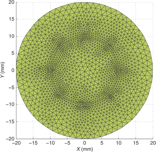
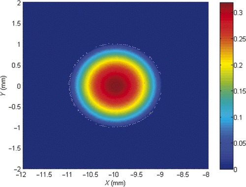
We first consider a single light source reconstruction problem. A light source of density S(x, y) = (1 − (x + 10)2 − y2)/π is placed on a circle centred at (−10, 0) with radius 1 mm. Let the permissible region Ω0 = {(x, y) | (x + 10)2 + y2 < 22}. We show the triangulation and the exact light source function S in and . Figures show approximate light source for partition with NT=968, N=502, NT=3872, N=1971 and NT=15488, N=7813, respectively. Each figure contains four pictures corresponding to r = 0, r = 0.5, r = 0.9 and r = 1. We conclude from these figures that the smaller the meshsize is, the better the light source reconstruction.
Figure 3. (Available in colour online). Reconstructed single light source with NT = 968, N = 502 for r = 0, r = 0.5, r = 0.9 and r = 1.
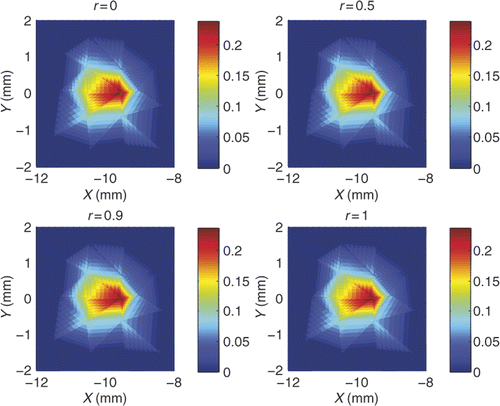
Figure 4. (Available in colour online). Reconstructed single light source with NT = 3872, N = 1971 for r = 0, r = 0.5, r = 0.9 and r = 1.
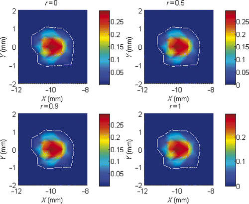
Figure 5. (Available in colour online). Reconstructed single light source with NT = 15488, N = 7813 for r = 0, r = 0.5, r = 0.9 and r = 1.
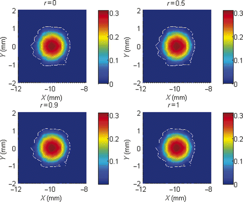
To see the influence of the parameter r on the accuracy of the numerical solution, we report in the numerical solution errors for several choices of the parameter. It can be seen from that for a fixed triangulation, error in approximate light source gets smaller slightly when the parameter becomes bigger until near r = 1. We also observe that it is possible to adjust the value of the parameter r so as to achieve better accuracy of the approximate light source function than the conventional formulation (r = 1, corresponding to a single forward boundary value problem). How to determine an optimal value for the parameter r is a topic worth further investigation. The numerical results also suggest that generally the conventional choice r = 1 is quite satisfactory.
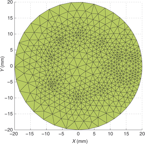
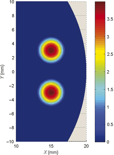
We then consider a reconstruction problem with two distinguish light sources. Place two circular light sources with radius 2 mm at (15, 3) and (15, −3), with densities 4 − (x − 15)2 − (y − 3)2 and 4 − (x − 15)2 − (y + 3)2, respectively. We choose the permissible region Ω0 = {(x, y) | (x − 15)2/9 + y2/100 < 1}. The triangulation and the exact light source function are plotted in and . Reconstructed light source functions are shown in and with partition of 1225 triangle elements and 637 nodes, and partition of 4900 triangle elements and 2498 nodes respectively.
Figure 8. (Available in colour online). Reconstructed multiple light source with 1225 elements and 637 nodes, r = 1.
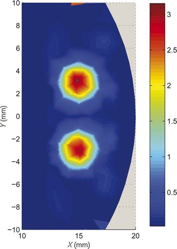
Figure 9. (Available in colour online). Reconstructed multiple light source with 4900 elements and 2498 nodes, r = 1.
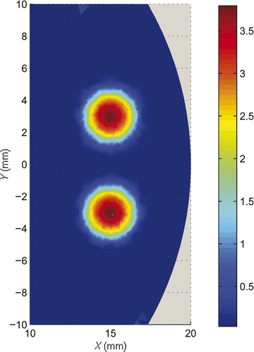
We observe that in all our numerical simulations, the light source functions are well reconstructed.
Acknowledgements
This work was supported by the National Science Foundation of China under Grant No. 10871179 and the National Basic Research Programme of China under Grant No. 2008CB717806.
References
- Douraghy, A, Prout, DL, Silverman, RW, and Chatziioannou, AF, 2006. Evaluation of scintillator afterglow for use in a combined optical and PET imaging tomography, Nucl. Instr. Meth. A 569 (2006), pp. 557–562.
- Loo, WT, Tong, JM, Cheung, MN, and Chow, LW, 2006. A new predictive and prognostic marker (ATP bioluminescence and positron emission tomography) in vivo and in vitro for delivering adjuvant treatment plan to invasive breast tumor patients, Biomed. Pharmacother. 60 (2006), pp. 285–288.
- Genove, G, DeMarco, U, Xu, H, Goins, WF, and Ahrens, ET, 2005. A new transgene reporter for in vivo magnetic resonance imaging, Nat. Med. 11 (2005), pp. 450–454.
- Weissleder, R, and Ntziachristos, V, 2003. Shedding light onto live molecular targets, Nat. Med. 9 (2003), pp. 123–128.
- Boas, D, Brooks, DH, Miller, EL, DiMarzio, CA, Kilmer, M, Gaudette, RJ, and Zhang, Q, 2001. Imaging the body with diffuse optical tomography, IEEE Signal Process. Mag. 18 (2001), pp. 57–75.
- Cong, WX, Kumar, D, Liu, Y, Cong, A, and Wang, G, 2004. A practical method to determine the light source distribution in bioluminescent imaging, Proc. SPIE 5535 (2004), pp. 679–686.
- Gu, X, Zhang, Q, Larcom, L, and Jiang, H, 2004. Three dimensional bioluminescence tomography with model-based reconstrution, Opt. Express 12 (2004), pp. 3996–4000.
- Alexandrakis, G, Rannou, FR, and Chatziioannou, AF, 2005. Tomographic bioluminescence imaging by use of a combined optical-PET (OPET) system: A computer simulation feasibility study, Phys. Med. Biol. 50 (2005), pp. 4225–4241.
- Chaudari, AJ, Darvas, F, Bading, JR, Moats, RA, Conti, PS, Smith, DJ, Cherry, SR, and Leahy, RM, 2005. Hyperspectral and multispectral bioluminescence optical tomography for small animal imaging, Phys. Med. Biol. 50 (2005), pp. 5421–5441.
- Cheng, X-L, Gong, R-F, and Han, W, 2008. A new general mathematical framework for bioluminescence tomography, Comput. Methods Appl. Mech. Eng. 197 (2008), pp. 524–535.
- Cong, WX, Durairaj, K, Wang, LV, and Wang, G, 2006. A Born-type approximation method for bioluminescence tomography, Med. Phys. 33 (2006), pp. 679–686.
- Han, W, Cong, WX, and Wang, G, 2006. Mathematical theory and numerical analysis of bioluminescence tomography, Inverse Probl. 22 (2006), pp. 1659–1675.
- Han, W, Cong, WX, and Wang, G, 2006. Mathematical study and numerical simulation of multispectral bioluminescence tomography, Int. J. Biomed. Imag. 2006 (2006), Article ID 54390.
- Han, W, and Wang, G, 2007. Theoretical and numerical analysis on multispectral boluminescence tomography, IMA J. Appl. Math. 72 (2007), pp. 67–85.
- Kwon, K, Yazici, B, and Guven, M, 2006. Two-level domain decompostion methods for diffuse optical tomography, Inverse Probl. 22 (2006), pp. 1533–1559.
- Slavine, NV, Lewis, MA, Richer, E, and Antich, PP, 2006. Iterative reconstruction method for light emitting sources based on the diffusion equation, Med. Phys. 33 (2006), pp. 61–69.
- Li, H, Tian, J, Zhu, F, Cong, WX, Wang, LV, Hoffman, EA, and Wang, G, 2004. A mouse optical simulation environment (MOSE) to investigate bioluminescent phenomena in the living mouse with the Monte Carlo method, Acad. Radiol. 11 (2004), pp. 1029–1038.
- Natterer, F, and Wübbeling, F, 2001. "Mathematical Methods in Image Reconstruction". In: , SIAM Monographs on Mathematical Modeling and Computation,. Philadelphia, PA: SIAM; 2001.
- Acosta, E, and Vazquez, D, 2005. Tomographic method for measurement of the gradient refracitve index of the crystalline lens I: The spherical fish lens, J. Opt. Soc. Am. A 22 (2005), pp. 424–433.
- Barakat, N, El-Hennawi, HA, El-Ghandoor, H, Hassan, R, and El-Diasty, F, 2001. Three-dimensional refractive index profile of a HRIN optical waveguide using multiple beam interference fringes, Opt. Commun. 191 (2001), pp. 39–47.
- Ferwerda, HA, 1999. The radiative transfer equation for scattering media with spatially varying refractive index, J. Opt. A: Pure Appl. Opt. 1 (1999), pp. L1–2.
- Khan, T, and Jiang, H, 2003. A new diffusion approximation to the radiative transfer equation for scattering media with spatially varying refractive indices, J. Opt. A: Pure Appl. Opt. 5 (2003), pp. 137–141.
- Khan, T, and Thomas, A, 2005. Comparison of PN or spherical harmonics approximation for scattering media with spatiall varying and spatially constant refractive indices, Opt. Commun. 255 (2005), pp. 130–166.
- Shendeleva, ML, 2004. Radiative transfer in a turbid medium with a varying refractive index: Comment, J. Opt. Soc. Am. A 21 (2004), pp. 2464–2467.
- Tualle, JM, and Tinet, E, 2003. Derivation of the radiative transfer equation for scattering media with a spatially varying refractive index, Opt. Commun. 228 (2003), pp. 33–38.
- Khan, T, and Thomas, A, 2006. Inverse problem in refractive index based optical tomography, Inverse Probl. 22 (2006), pp. 1121–1137.
- Khan, T, Thomas, A, and Yoon, JR, 2006. On uniqueness in refractive index optical tomography, Inverse Probl. 22 (2006), pp. L1–L5.
- Atkinson, K, and Han, W, 2005. Theoretical Numerical Analysis: A Functional Analysis Framework . New York: Springer-Verlag; 2005.
- Franklin, JN, 1974. On Tikhonov's method for ill-posed problems, Math. Comp. 28 (1974), pp. 889–907.
- Isakov, V, 2006. Inverse Problems for Partial Differential Equations. New York: Springer; 2006.
- Kirsch, A, 1996. "An Introduction to the Mathematical Theory of Inverse Problems". In: , Applied Mathematical Sciences,. Vol. 120. New York: Springer-Verlag; 1996.
- Grisvard, P, 1985. Elliptic Problems in Nonsmooth Domains. Boston: Pitman; 1985.
- Saad, Y, 2003. Iterative Methods for Sparse Linear Systems. Philadelphia: SIAM; 2003.
