Abstract
Thick rubber part moulding is a process, during which coupling between heat and chemical kinetic equations is strong. Automatic tooling control, therefore, is the guarantee of achieving proper curing within the mould. This article initially presents a detailed method for curing optimization. With this aim in view, the optimum temperature cycle for the desired curing state is examined. The use, here, of the conjugate gradient method implies to determine the solution of both adjoin and sensitivity equations. A sensitivity study is also conducted in order to improve the kinetic model. Finally, some optimization examples are discussed.
Nomenclature
| α | = | vulcanization rate |
| = | desired vulcanization rate | |
| β | = | coefficient in the descent direction |
| δT | = | small variation of temperature (K) |
| Δ | = | Laplacian operator |
| ΔH | = | vulcanization enthalpy (J kg−1) |
| = | Lagrangian multipliers | |
| Γ | = | boundaries |
| λ | = | thermal conductivity (W(mk)−1 |
| µ | = | descent depth |
| Λ | = | density (kg m−3) |
| σk | = | function of time (value 0 or 1) |
| Ω | = | studied part |
| c | = | heat capacity (J (kg K)−1) |
| d | = | descent direction |
| E | = | activation energy (J mol−1) |
| F | = | kinetic function (s−1) |
| h | = | heat transfer coefficient (W m−2 K−1) |
| J | = | criterion |
| k | = | thermal function in the kinetic function (s−1) |
| k0 | = | coefficient in k (s−1) |
| L | = | Lagrangian function |
| n | = | coefficient in the kinetic function or iteration number |
| Np | = | number of set value parameters |
| Nt | = | number of instant during the curing phase |
| Nz | = | number of points in the thickness |
| r | = | radius (m) |
| R | = | residual error |
| R | = | constant (8314 J (mol K)−1) |
| Sk | = | sensitivity coefficients |
| t | = | time (s) |
| t′ | = | part ejection time (s) |
| T | = | temperature (°C) |
| T+ | = | upper mould prescribed temperature (°C) |
| T− | = | lower mould prescribed temperature (°C) |
| ti | = | induction time (s) |
| = | reduced induction time (s) | |
| t0 | = | coefficient in the induction time (s) |
| TB | = | coefficient in the induction time (K) |
| Text | = | ambient temperature (K) |
| W | = | induction function |
| z | = | position on the symmetric axis (m) |
| c | = | rubber |
| ext | = | ambient |
| i | = | induction |
| is | = | insulating guarding element |
| m | = | mould |
| ′ | = | cooling phase |
1. Introduction
The present article reports part of a wide-ranging study conducted in collaboration with many companies of the rubber industry within the context of a joint research programme. This article addresses the problem of the optimization of the curing cycles of thick elastomer moulded parts. Rubber, indeed, is a sensitive material whose low thermal diffusivity results in a considerable curing time. Moreover, when initiating the vulcanization chemical reaction, the temperature of the part must be brought up to at least 120°C. Consequently, thick rubber part production is complex and difficult to control.
During thick part classical moulding process, rubber is placed (or injected) within an already heated mould and kept at the right temperature for the duration of complete vulcanization phase. Curing times are experimentally determined whereas a posterior control of the moulded part quality is performed. The parts are then ejected from the mould, but it is not unusual to observe that curing continues up to the storage phase. The objective of this research is to propose a curing processing method for thick elastomer parts. This method could be used to control and check part quality, to limit refuses and to reduce energy costs during production.
The optimization of the mould thermal control cycle to achieve qualified characteristics of the part at the end of the cooling stage, which, most of the time, ends after ejection, is discussed. The direct problem is defined by the coupled solution of the energy equation with a source term and of the rubber chemical kinetics equation. The problem is a 2D and axisymetric system. Moreover, the consideration of the change at the boundary limits during the process is necessary. The conductive heat transfer conditions found within the mould, indeed, changes, after ejection, into radiative-convective heat transfer conditions between the moulded part and the ambient air of the production department.
In order to determine the optimum prescribed temperatures (mould thermal control temperatures), an inverse problem, based on the minimization of the difference between the recorded and the desired reaction progresses at the end of the cooling phase, is considered. Considering the objective, this constrained optimization is achieved using the conjugate gradient method Citation1. Both the descent direction and the descent depth are obtained by solving the adjoint and sensitivity equation system. The inverse problem, however, is an ill-posed problem Citation2. Possible regularization consists in considering industrial process constraints to define the area of the solution domain. Because the experimental mould used here Citation3, like industrial moulds, is limited in terms of both heating and cooling rates and temperature levels, the consideration of these technological constraints makes it possible to achieve realistic prescribed temperatures.
The major difficulty facing the determination of the optimum is the difference of sensitivity to the reaction progress at the end of the cooling phase on the temperatures defining the curing cycle. Disparity, here, is due to the duration of the experiment, on the one hand, and to the chemical kinetics model characteristics, on the other hand. The length of the rubber induction period (or inhibition time Citation4) is connected to the elastomer temperature history. As long as the chemical reaction is not initiated, the temperature cycle presents no sensitivity. Inhibition time, here, prolongs significantly the time horizon, for which optimization using ‘traditional’ kinetics models is difficult or even impossible. The induction period is then integrated into the cure rate to demonstrate how some model modifications enhance optimization considerably.
Because of their industrial character, studies addressing elastomer thermal cycles are very few in the literature. Bertrand Garnier's research work, however, on heat transfer modelling during elastomer production, contributes significantly towards the characterization of their thermal specifications Citation4. Recently, some studies, whose objective was to examine curing cycles, have been conducted by Jarny et al. Citation5,Citation6. More recently and with a similar objectives to ours, Le Bideau and Al Citation7 have studied the vulcanization of thin elastomer pieces using infrared heating process.
2. Direct problem
2.1. Formulation of the problem
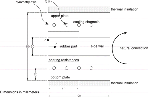
The direct problem simulates the curing cycle of a 100 mm diameter and 30 mm thick elastomer cylinder within a temperature-controlled Ampco® beryllium bronze mould (). Both heating and cooling controls are provided. The cooling phase out of the mould is also considered. Inside the mould, a whole thermal cycle is run for complete or partial vulcanization of the initially cold elastomer. The energy required to heat the rubber material is provided by temperature-controlled heating plates. These plates are designed to give out some uniform surface temperatures and output power.
The side wall of the mould is made of a Deltherm® material with thermal characteristics similar to rubber and a mechanical strength high enough to withstand the pressure from the press, within which the mould stands. It, thus, makes it possible to achieve unidirectional heat transfer towards the elastomer z-axis.
2.2. Problem modelling
2.2.1. Problem geometry
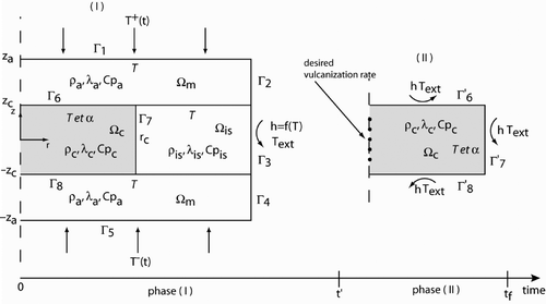
presents the scope of study of the 2-D axisymetric direct problem. represents the metal range of the mould (Ampco®),
represents the insulating guarding element (Deltherm®) and
represents the rubber part.
and
represent the mould temperatures that are to be prescribed in order to optimize the curing. The computing interval is divided into two periods: a first period between 0 and
(curing phase inside the mould) and a second period between
and tf (natural convection and radiative cooling phase out of the mould).
gives the material properties of the mould. The consideration of the temperature dependence of NR THERMEL1 rubber specific heat is justified by the strong sensitivity of the computed temperatures to this value.
Table 1. Thermophysical properties of the mould and part constituents.
2.2.2. Direct problem equations
As stated previously, we separate the direct problem into two simpler problem phases: one inside the mould and another outside the mould with surrounding air. Depending on the phase, the problem is defined by the following equation systems.
2.2.2.1. Phase (I)
Depending on whether the mould or the rubber material is considered, the heat equation takes a different form. For the mould (), the thermophysical parameters are assumed to be constant and the heat equation takes the form:
(1)
For rubber (
), the experimental results for the thermophysical parameters show that the heat capacity alone varies significantly with the temperature. Consequently, the evolution according to the temperature is considered for this parameter only. Inside the mould cavity, the heat liberated by the elastomer during vulcanization appears in the heat equation as
(2)
In this equation, α represent the vulcanization rate,
. It can be characterized mechanically and thermically.
We have the following initial and thermal boundary conditions for the mould-part system:
(3)
(4)
(5)
(6)
The direct problem also includes the vulcanization kinetics equation. Its terms are experimentally determined from the thermomechanical measurements. We consider an Isayev model Citation8, which differentiates between the thermal and the autocatalytic effects of the reaction. The vulcanization kinetics equation is then written as
(7)
We introduce in Equation (7) the function W which depends on the reduced induction time:
in Equation (8):
(8)
Before the starting of the vulcanization itself, a chemical reaction of consumption of retarding agents occurs (induction reaction). This reaction is characterized by a time called ‘induction time ti’ which is thermo-dependent (Arrhenius law). This variable is thus defined in any point of the reactive system, therefore of the part. The reaction induction period depends on the material temperature history. So as long as these retarding agents are not consumed by the chemical reaction, the vulcanization could not begin. With this consideration and to describe the evolution of inhibitive reaction during the time, the following relationship is written, in every point, as:
(9)
with
(10)
We used a reduced induction time ti as defined by Isayev and Wan Citation8 of which expression is based over an isothermal induction time (Equation (10)).
and t0 are the two constants coefficients of the Arrhenius law describing the induction time evolution.
The second term of Equation (7) is defined as follows:
(11)
(12)
Equation (11) describes the evolution of the vulcanization reaction speed which is depending on temperature and vulcanization rate α as an autocatalytic model.
The coupled kinetics equation involves an initial condition, for which rubber is assumed raw, defined as
(13)
NR THERMEL1 kinetics parameters are described in .
Table 2. Kinetics parameters for THERMEL1 natural rubber.
2.2.2.2. Phase (II)
During this phase, the rubber part is ejected at the time t′ from the mould and cools in contact with the production department ambient air through convective and radiative heat exchanges. The problem reduces to the domain. The heat equation is identical to phase (I), that is,
(14)
The initial condition of the second phase is given by the final condition of the first phase (Equation (15)). Boundary conditions are taken to be identical for all part faces provided they are assumed to be a Fourier condition, for which the coefficient, h(T), stands for the overall coefficient of natural convective and radiative heat transfer (Equation (16)). It stands to reason that, as rubber cools down, the exchange coefficient decreases in time as a function of the specimen surface temperature, T. Heat transfer coefficient modelling is classical using the law of thermal radiation and a correlation for the natural convection problem.
(15)
(16)
The kinetics equations are the same as those given for phase (I) and are described by Equations (7–13).
The initial vulcanization rate of the second phase (II) is given by the vulcanization rate at the end of the first phase (I).
2.3. Example of calculation method for direct problem solution
The solution of the coupled equation system is obtained using COMSOL software (www.comsol.com). The temperature set value boundary conditions are represented as a function of time (Equations (4) and (5)), so their values must be known for every time step of the calculation. But, in reality, we define our boundary conditions for few points in the time horizon. This reduction of the number of parameters to be estimated and the use of a independent functions σk to describe the temperature allows to improve the solution research and to make the resolution of the inverse problem reliable. We obtain
(17)
where Np represents the number of set value parameters and
the functions defined by Equation (18).
(18)
In Example 1 in
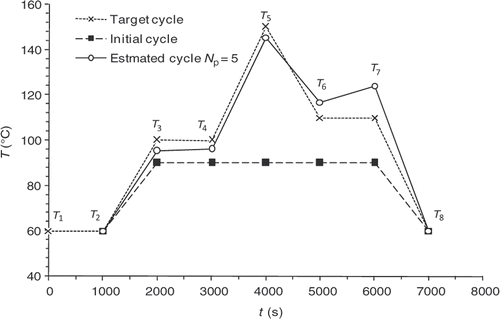
and time/temperature couples are given in . We arbitrarily chose eight parameters to describe a multi stages curing cycle and to test different cycles shape.
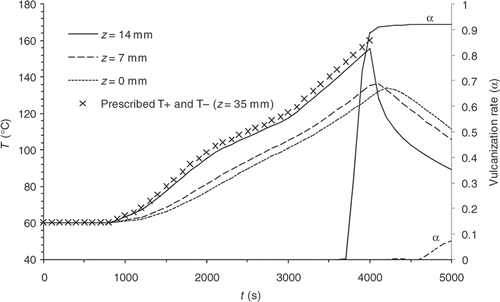
Figure 3. Example 1, cooling inside the mould – – Temperatures and vulcanization rate computed at different points of the part.
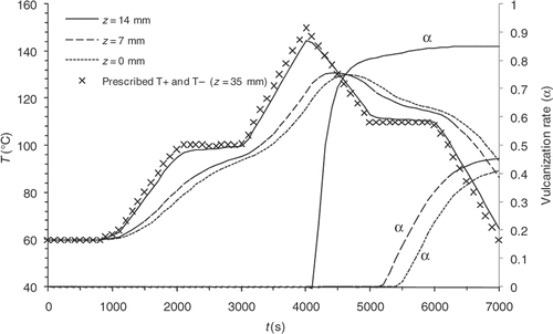
Table 3. Discretization of the prescribed temperatures.
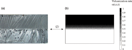
The validity of the thermal direct problem solution was demonstrated with a system of measurement of the temperatures within the part during moulding Citation3. The displays of the vulcanization front on a moulded part and the comparison with the computed progress front have made it possible to validate the kinetics direct problem partially. One result for the thermal field is shown in . The comparison between experimental measurements and our numerical model solution give a good agreement. In the same way, presents the comparison between experimental vulcanization front position and the calculated one. The results also showed, a good agreement.
Figure 4. Experimental and theoretical temperature values achieved in different points of the moulded part during a moulding cycle.
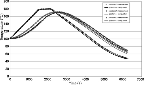
Figure 5. Comparison between the vulcanization front position obtained experimentally (a) and calculated (b).
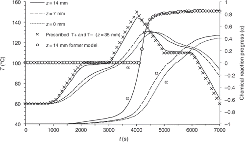
As examples, and illustrate the results of two direct computations carried out with different prescribed temperatures. In Example 1 curing and cooling phases take place within the mould, whereas, in Example 2 the cooling phase is observed outside the mould. and show the evolution of the temperatures on the symmetry axis of the part in z = 0 mm (centre), z = 7 mm and z = 14 mm (close to the surface), and display the reaction progress at the same points. Under these simulated conditions, the reaction induction period lasts approximately 4000 s.
3. Sensitivity study and kinetics model enhancement
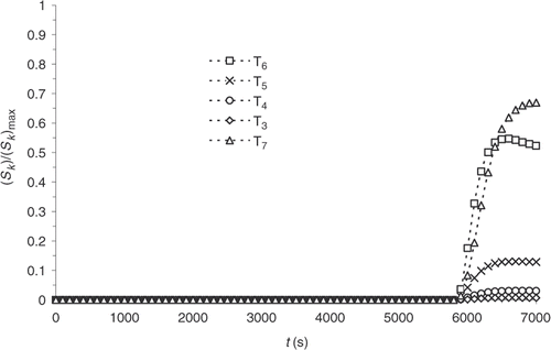
The results observed in and can raise some doubts as to the feasibility of curing cycle optimization. The reaction progress, indeed, being non-existent for a significant length of the reaction, a sensitivity study is conducted. Considering Example 1, the sensitivity coefficients, Sk, corresponding to the response of the system to a small variation, , of one the prescribed temperature, Tk, are defined.
(19)
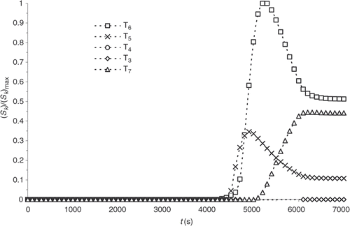
and shows the evolution time of the standardized sensitivity coefficients at the surface and within the part, respectively. The sensitivities are calculated with the direct problem conditions presented in .
We note that the values are highly heterogeneous at the different prescribed temperature, on the one hand, and that sensitivity is non-existent during most of the experiment, on the other hand. Consequently, a variation of one of the prescribed temperatures below the first 4000 s of the thermal control cycle virtually does not affect the reaction progress distribution.
This restricting result as regards optimization perfecting reveals the inadequacy of the kinetics physical model used here. It, indeed, considers the reaction induction period through the definition of an induction time, below which progress is non-existent (Equation (9)). In reality, a reaction mechanism is initiated during the rubber heating and its progression can be quantified. Instead of describing the induction phase like a delay of the starting of the vulcanization reaction, we propose to describe the progression of the reaction during the induction phase. So, we propose that the reaction progress now varies linearly between −1 and 0 during the induction period to describe the inhibition reaction. The choice of the evolution interval (−1 to 0) was made to obtain a same evolution range that the vulcanization rate has. The negative values of the chemical reaction progress during the induction phase makes it possible to distinguish the induction reaction from the vulcanization one.
(20)
with the new initial condition
(21)
illustrates the change obtained on the reaction progress evolution for Example 1, shown in .
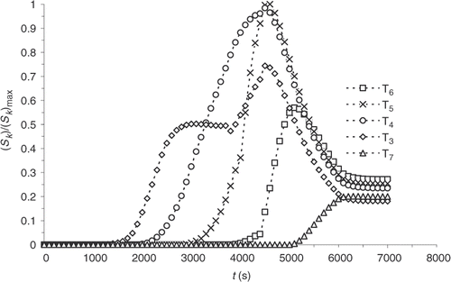
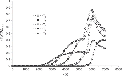
and present the sensitivity computed with the new model. Sensitivity coefficients are more homogeneous and noticeable from the beginning of the experiment. The correction, within an optimization algorithm, of the temperatures, at which a new cycle begins, is then possible. The sensitivity of the part centre also increases. Consequently, a more complete description of the chemical progress of reaction is used for the solution of the inverse problem discussed below.
4. Inverse problem
4.1. Presentation
The solution for the optimization problem developed here is obtained from the determination of the boundary limits and
(Equations (4) and (5)). They are essential to reach the desired reaction progress at certain times of the curing phase and make sure it becomes stabilized at the end of the cooling phase. We define a least squares criterion, J.
(22)
With a Lagrangian multipliers approach, we find the following criterion gradient (Equation (23)):
(23)
Finally, the descent depth is explicitly expressed, by the resolution of the sensitivities equations, as
(24)
More details are given in the Appendix.
The constraints on the heating and cooling rate, dT/dt, are not taken into account explicitly in the criterion of the optimization method, but they are introduced in the algorithm in order to reduce the solutions that exceed the maximum rate into that maximum. The heating and cooling rate limits are imposed by the experimental device.
4.2. Numerical validation
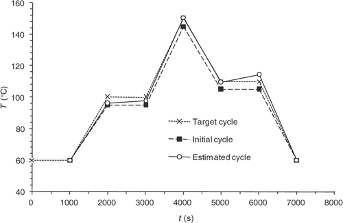
In order to test and discuss the optimization method described above, a numerical validation study with a reference control cycle, called the target cycle, is conducted (). Solving the direct problem using this target cycle makes it possible to know the temperature and reaction progress information at any point of the domain and for all the time steps. We then obtain the values of , which are the observable quantities, from which the algorithm is trying to find the target cycle.
represents the target state of cure defined by the user in various locations of the part and at various moments. This state of cure is not measured, but it is that which one to consider during optimization. The application of the calculated cycle conduce to the desired state of vulcanization at the end of the curing cycle. Here
| • | |||||
| • |
| ||||
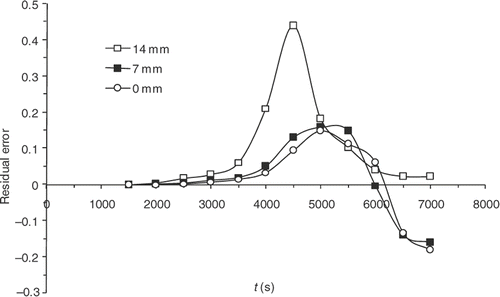
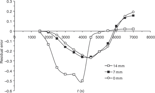
Finally, although the kinetics model has improved significantly, sensitivities are still maximal when the reaction starts, i.e. around 4000 s (). presents the residual errors, . displays the evolution of
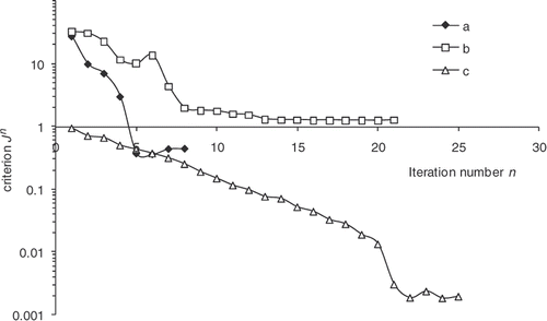
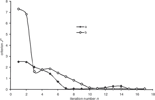
as a function of the iteration number, which confirms the algorithm convergence (least squares criterion within the range 30–0.4). The residual errors are considerable at the surface of the part and between 4000 and 5000 s. This interval corresponds to the time interval, during which the chemical kinetics rate is the highest (). The high-kinetics velocity hinders the search for the optimum. The difference between the target temperature #7 and the estimated temperature underlines the difficulties met by the algorithm between 4000 and 5000 s.
5. Initial cycle effect
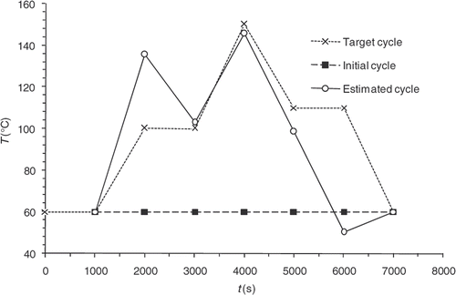
The convergence of the inverse algorithm is highly sensitive to the initial temperature cycle. We have presented in an example looking for optimum cycle starting from a very simple initial cycle. The results are very encouraging with residual error that does not exceed 0.4 at the part centre during reaction (). The algorithm converges in 7–8 iterations for a final criterion of 0.5 (). In we present an initial cycle with low constant temperature. We notice immediately the difficulty for the algorithm to find the target cycle and oscillations occur. For this cycle, the residual errors () are more important than in the previous case. In we also highlight the difficulty faced by the algorithm to converge, more than 20 iterations for a final criterion have value higher than 1. We therefore conclude by this case that the choice of the initial cycle must be made by someone who knows quite well the rubber behavior. The initial cycle must allow the start of the curing reaction in order to expect a convergence. This phenomenon has already been highlighted by Bailleul et al. Citation9. In we also present the case, less likely, of an initial cycle very close to the target cycle. We note that the algorithm performs very well the temperature corrections. In this case, convergence is fast, as shown in , the criterion is equivalent to our first case (0.5) in four iterations.
In the previous example, we defined a target state of cure profile throughout the cycle time (Nt = 12). However, the industry cannot define a criterion over the cycle time. The multiplicity of the rubber application fields leads to as many optimum vulcanization profiles as applications. However, very often, professionals need a state of cure at the end of the curing cycle (Nt = 1). We therefore chose to develop our algorithm in order to take into consideration several possible configurations. Therefore, it offers the possibility for users to define their vulcanization profile in all of the cycle time or part of it.
In , we presented the case that calculates the optimum cycle for state of cure profiles defined on the entire cycle time (Nt = 12). We show the very good convergence of the algorithm. In , we present a case in which the state of cure profile is only defined at the end of the cycle time (Nt = 1). In this case, more difficult for convergence, it is imperative to have an initial cycle close to the final solution. Reducing the defined state of cure profile number (Nt) in the cycle time leads to increase difficulties of the algorithm convergence.
6. Examples of optimization
To illustrate the potential of the method and its application to industrial problems, the following two examples of optimization are considered.
6.1. Cooling within the mould
The first example consists in adapting cooling within the mould so as to obtain rubber parts, which might be considered as homogeneous regarding reaction progress within the depth of the part. The desired stabilized progress within the depth of the part at the end of the cycle is 0.9. The number of points in the criterion is at the instants
and
, which corresponds to stabilized progress at the end of the cycle. The cycle is represented by eight points of temperatures. The first and the last points being set, there are
‘free’ parameters to identify. The first value of cycle (T1) is imposed like the temperature initial of the rubber. The mould is cold. The last (T8) is imposed under the vulcanization temperature to stabilize the chemical reaction progress.
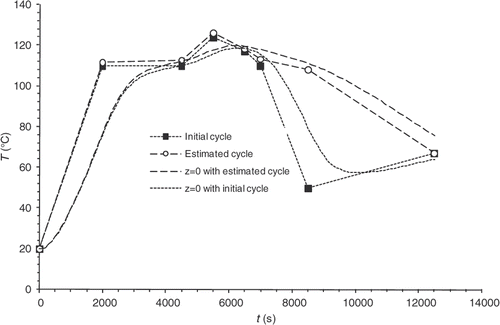
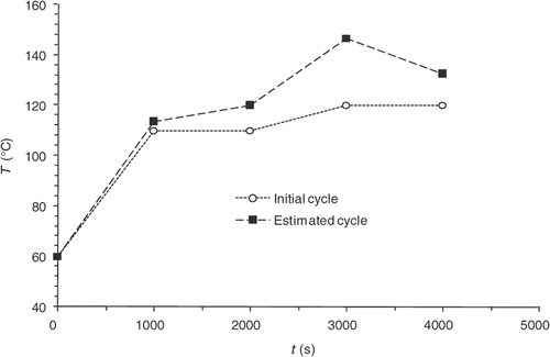
presents the estimated cycle after convergence coupled with the initial cycle used to start the optimization. Least-squares criterion history is shown in . The sensitivity problems discussed above account for the fact that corrections are very small at the beginning of the cycle and considerable between 8000 and 10,000 s. This interval corresponds to the moment where the rate of the chemical kinetics is the highest.
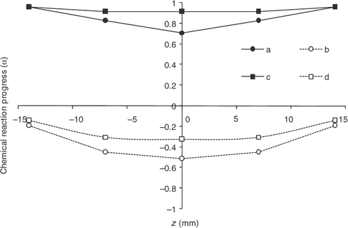
displays the reaction progress distribution, α, within the depth of the part at the end of the cooling phase () obtained with the initial cycle (mean progress of 0.3), on the one hand, and with the optimized cycle, on the other hand. We note that the optimization is effective. Progress, however, appears always greater on the edges than in the centre of the part. Indeed, because of the low-exothermic reaction and low-diffusive material, removing totally this progress difference between centre and surface is impossible. The estimated cycle, however, reduces the difference between the surface and the centre of the part and makes it possible to obtain a mean progress close to 0.8.
6.2. Cooling outside the mould
The innovative approach presented in this research work as regards its industrial applications consists in using the cooling phase outside the mould (the part is ejected and cooled by natural convection) to reduce time in the mould and increase production rates. The optimization is not directed on the study of the curing cycle to achieve a qualified curing state upon ejection anymore. Instead of it, it focuses on the achievement of a qualified curing state at the end of the cooling phase outside the mould. Here, for instance, the desired reaction progress is 0.9 at (end of phase 2: cooling outside the mould). In order to operate superficial curing sufficient for the part to be ejected, an additional desired progress of 0.9 for the part surface is added in the criterion at
(end of phase 1: ejection of the part). presents the initial temperature cycle and the optimized cycle obtained after the algorithm has converged. is used to check that the residual errors at the criterion points are very small.
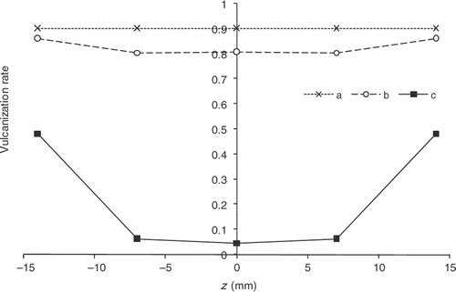
gives the reaction progress distributions within the part thickness both at the ejection point and at the end of the cooling phase. The difference between these distributions and the distributions obtained with the initial cycle is considerable. After convergence, the progress observed at the part surface is definitely 0.9. However, the gradient remaining within the thickness proves difficult to remove.
Figure 22. Chemical reaction progress within the part thickness. Desired vulcanization rate: 0.9 – a: α obtained at the end of heating in the mould with the estimated cycle, b: α obtained at the end of heating in the mould with the initial cycle, c: α obtained at the end of cooling outside the mould with the estimated cycle, d: α obtained at the end of cooling outside the mould with the initial cycle.
7. Conclusion
The present article reports a study conducted to examine the optimization of natural rubber curing cycles. The objective of this research was to obtain a controlled vulcanization state at the end of the cooling phase.
In order to address this objective, a new model to characterize the vulcanization rate has been developed by the authors. Inhibition, which is a chemical reaction in the same way as the vulcanization reaction, is now considered through the definition of an artificial negative vulcanization rate ranging from −1 to 0 (the instant when all inhibitors are consumed and the chemical reaction starts). This subterfuge permits to increase the sensitivity on short times and widen the optimization range of the thermal cycle.
The other original aspect of this research consists in the modification in the boundary limits in time, which change from a temperature imposed by the mould walls into a radiative-convective condition outside the mould. The consideration of the phase outside the mould and the determination of a target at the end of the cooling phase can significantly reduce the mould immobilization time and generate a productivity increase, which is attractive for manufacturers.
Acknowledgements
This study comes within the context of the ‘Thermel1’ research programme initiated by the LRCCP. Special thanks to all Thermel1 partners and, in particular, to the LRCCP, Michelin, Hutchinson, GEFFICA, SPBT, SACATEC, SACRED companies for their technical assistance and financial support.
References
- J. Legras, Algorithmes et Programmes d’optimisation Non-linéaire Avec Contraintes. Application au Contrôl Optimal, MASSON, Paris, 1980..
- Beck, JV, 1985. Inverse Heat Conduction: Ill Posed Problem. New York: Wiley Interscience; 1985.
- El Labban, A, Mousseau, P, Deterre, R, and Bailleul, J-L, 2009. Temperature measurement and control within moulded rubber during vulcanization process, Measurement 42 (2009), pp. 916–926.
- B. Garnier, Etude du couplage entre transferts thermiques et une reaction chimique. Application à la vulcanisation du caoutchouc, Ph.D. thesis, Université de Nantes, 1990..
- Jarny, Y, Delaunay, D, and Brizaut, J-SLe, , Inverse analysis of the elastomer cure control of vulcanisation degree, 1st International Conference on Inverse Problems in Engineering, Theory and Practice, Palm Coast, FL, 13–18 June 1993..
- Bailleul, J-L, Jarny, Y, Delaunay, D, Amiaud, S, and Brizaut, J-SLe, , Characterization of heat sources in materials during transformation. Experimental validations with rubber and epoxy resin, Proceedings of the Xth Int. Heat Transfer Conference, Brigthon, (1994), pp203–208..
- Le Bideau, P, Ploteau, J-P, Dutournié, P, and Glouannec, P, 2009. Experimental and modelling study of superficial elastomer vulcanization by short wave infrared radiation, Int. J. Ther. Sci. 48 (3) (2009), pp. 573–582.
- Isayev, AI, and Wan, M, 1996. Injection molding of rubber compound with rheology affected by vulcanisation. Part I: Material characterization, Rubber Chem. Technol. 69 (1996), pp. 277–293.
- Bailleul, J-L, Delaunay, D, and Jarny, Y, 1998. Optimal thermal processing of composite materials: An inverse algorithm and its experimental validation 11th International Heat and Temperature Conference. Vol. 5. 1998, Kyingju, Korea, pp. 87–92.
Appendix
The solution for the optimization problem developed here is obtained from the determination of the boundary limits and
. They are essential to reach the desired reaction progress at certain times of the curing phase and make sure it becomes stabilized at the end of the cooling phase. We define a least-squares criterion, J.
(25)
Where
is the desired progress, Nt is the number of instants during the curing phase, at which desired and computed progresses are going to be compared, and Nz is the number of points within the thickness and on the symmetry axis of the part used to compute the criterion.
To minimize the function ,
and
are determined using a conjugate gradient numerical optimization method. This iterative method consists in correcting the quasi-solution (
and
) for each iteration, n, by computing both the descent direction, d, and the descent depth, μ, as
(26)
The descent directions at n iteration are obtained from the directions at n − 1 iteration and from the gradient of the criterion
and
such as
(27)
The minimization problem for J can be written in the form of a constrained optimization problem since both variables, α and T, are the solutions of the heat and kinetics coupled equation system (Equations (2) and (7)). Its solution, which is obtainable from a classical inverse technique based on the combination of the Lagrangian multipliers with the system parameters (criterion J and constraints), is expressed in the form
(28)
where
are the Lagrangian multipliers (or adjoin variables) associated with the variables T and α in the first curing phase and
are the Lagrangian multipliers (or adjoin variables) associated with the variables T′ and α′ in the second curing phase.
Using the conjugate gradient method, we now reduce the constrained minimization problem to the minimization of L without constraint.
The variables of Equation (28) being independent, the solution of the Lagrangian minimization problem is taken as
(29)
(30)
The first four equations will make it possible to write the adjoin equation systems whereas the last two equations, which we are trying to obtain, will give the iterative algorithm gradient.
The solutions of Equations (29) and (30) are classical. Some traditional mathematical tools that are used to integrate by parts in order to obtain the domain boundaries and the derivatives are represented as
The consideration of the initial and boundary conditions of the direct problem makes it possible to simplify many terms and to obtain the adjoin equations. A very similar solution is presented by Bailleul et al. Citation9.
Once developed, the formulation of the adjoin problem obtained for both phases is given by Equations (31–45). The problem in phase 2 is solved first because the time boundary condition is a final condition (Equations (33) and (34)). The equations are strongly coupled with homogeneous boundary conditions and have the same form than those of the direct problem.
Phase (II):
(33)
(34)
(35)
(36)
(37)
Boundary condition change, i.e. the change from the phase out of the mould (phase II) to the phase inside the mould (phase I) is characterized by the continuity of the adjoin variables within the part (Equations (39) and (40)).
Phase (I):
(38)
(39)
(40)
(41)
(42)
(43)
(44)
(45)
(46)
(47)
with
Derivating the Lagrangian function according to variables and
yields
(48)
(49)
The temperature and the reaction progress rate being solutions of the direct problem, we obtain
(50)
Hence
(51)
The criterion gradients are then given by Equations (46), (47) and (49) in the form
(52)
The descent depth is determined using the sensitivity equations. The solution of these functions is obtainable by introducing the prescribed temperatures modified by the descent direction and the descent depth. We find
(53)
where μn is the descent direction at n iteration. This scalar quantity is defined so as to minimize the following functional J:
(54)
By Equation (25), we also have
(55)
The temperature distribution, T, and the vulcanization field, α correspond to the prescribed temperatures, T+ and T−. Similarly, the temperature distribution, Tμ, and the vulcanization field, αμ correspond to the prescribed temperatures, T++ μ.δT+ and T−+ μ.δT−. By using the notation
(56)
and establishing the equation systems for both set-value pairs. Then, by subtracting both systems and after that, by dividing by the descent depth and, finally, by considering the limit when it tends towards zero, the sensitivity equation systems for both curing phases are obtained.
Phase (I):
(57)
(58)
(59)
(60)
(61)
(62)
(63)
(64)
Phase (II):
(65)
(66)
(67)
(68)
(69)
(70)
(71)
By making use of the relations dn(T+) = δT+ and dn(T−) = δT from these systems, we obtain
(72)
Moreover, we already know that
(73)
Therefore, the gap functional becomes
(74)
In this formulation, temperature, T, and cure rate, α, are solutions of the direct problem. Moreover, δT and δα are solutions of the sensitivity equations. Thus, the gap functional, J, is now a function of the descent depth, μ, only. We find
(75)
Therefore, we try to determine the descent depth minimizing criterion J, now reduced to the equation of a parabola. So, a minimum appears only if coefficient c is positive. δα2 being positive, this is readily confirmed. The minimization of J then comes down to the determination of the descent depth value, for which the derivative of the criterion, as a function of μ, is equal to zero. We write
(76)
Finally, the descent depth is explicitly expressed as
(77)
