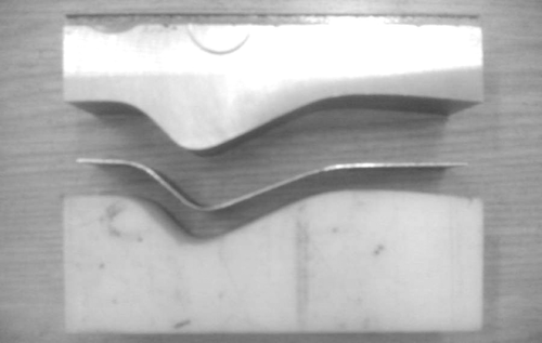
Abstract
Elastic recovery of a formed part in unloading, known as springback, causes shape errors in the final product of sheet metal forming processes. Several approaches have been proposed for the analysis of springback and compensating its error. The springback occurs at the last step of process and the final geometry of the work piece can be obtained at the end of direct process modelling. In this article, an algorithm for inverse springback modelling is presented. In this approach, required conditions for the inverse movement of final product towards the end of the loading state are prepared. Having the product geometry at the end of the loading, the geometry of die parts can be designed for the production of a target shape. For this inverse movement in FE modelling, the optimum constrained node and balanced contact forces are proposed in this algorithm. The presented approach is verified for symmetric and asymmetric bending processes. The results have shown that this approach can model symmetric and asymmetric processes inversely with tight tolerances. An optimization algorithm for compensating springback error and iterative tool design is presented based on inverse modelling. This algorithm is verified on symmetric V-bending process and its convergence rate is compared to the direct trial trend. The inverse approach shows more convergence rate in this comparison. Performing an experimental test on symmetric V-bending and asymmetric bending processes, the accuracy of the presented algorithms is investigated. The results show that the presented algorithms are efficient and accurate in both cases.
1. Introduction
Sheet metal forming is one of the most common manufacturing processes for parts used in various industries such as inner and outer panels and stiffeners in automotive and aeronautic industries, food cans and civil engineering applications. A wide range of these products should satisfy tight tolerances compared to desired geometry. In most processes, the geometry and configuration of die components could be obtained from the geometry of the product at the end of loading. Therefore, elastic recovery of the formed part in unloading, known as springback, is the most important factor in the deviation of the final product from its desired geometry.
Springback is influenced by a combination of various process parameters such as tool shape and dimension, contact friction condition, material properties, thickness, etc. Citation1. In recent years, finite element analysis (FEA) has been considered an effective tool for simulating the sheet metal forming processes and predicting the springback Citation2.
The most applied method in sheet forming analysis is the incremental finite element method (FEM). By considering the appropriate elastic–plastic model of material behaviour, contact condition of die and work piece, numerical solution method and modelling assumptions, accurate analysis of process become possible Citation3. In spite of the accuracy of incremental FEM in the analysis of sheet metal forming processes, enormous time and cost is needed for process design by this method. An iterative analysis is required to satisfy each design criteria for process design. For saving time and money, several approaches for one-step analysis of sheet forming processes are presented Citation4,Citation5. Such approaches are not as accurate as FEM, but are fast and suitable for preliminary process design.
The greatest group of one-step analysis is the inverse approach. In the inverse approach, the final product corresponding to the desired part is assumed at the first step of analysis and by the one-step calculation, the initial process setting will be obtained. Batoz et al. Citation6,Citation7 have represented an inverse approach for finding the optimum blank shape to obtain the desired characteristics of a product such as uniform flange width and thickness change. Unlike the FEM that iterates for finding a blank shape to obtain the desired shape, their approach represents the blank shape in an inverse step. The springback effect is not considered in their approach.
Two groups of research have been performed for controlling springback deviations. The first group focused on mechanical methods for the reduction of springback by increasing sheet tension during the forming process Citation8–11. Applying such methods cause a greater plastic zone during forming and less springback occurs during unloading. Although these approaches are efficient in many processes, increasing tension causes tearing of the work piece in many forming operations.
In the second group, the purpose is to compensate springback error by the modification of tool design, in a way that the target shape results after springback. In such methods, the amount of springback is considerable, but by accurate springback analysis and applying trial-error algorithms, this error would be compensated by the correction of die geometry. In industrial practice, deformations due to springback are compensated manually by doing extensive measurements on prototype parts and altering the tool geometry by hand, which is a time-consuming process. Applying FEM, several approaches for compensating springback error have been presented. Gan and Wagoner Citation12,Citation13 proposed a geometrical method, ‘Displacement Adjustment method (DA)’, for compensating springback error by trial modification of the die surface in the opposite direction of springback. They investigated the efficiency of their method compared to other approaches such as the ‘Force Descriptor Method (FDM)’. The FDM is presented by Karafillis and Boyce Citation14–16 for the inverse design of die geometry, considering the springback error. FDM has a convergence and accuracy problem in processes with asymmetric physics and a large amount of springback; therefore, it is only efficient for symmetric problems Citation12,Citation16. The DA method has some advantages compared to FDM Citation12, but could not converge to the curved features in the ‘side wall’ area Citation17. Similar approaches have been presented by Cheng et al. Citation17, Wu et al. Citation18, Anagnostou Citation19 and Lingbeek et al. Citation20.
Inverse analysis of springback could be applied for obtaining process geometry in a way that the final part corresponds to the desired shape. In this article, a springback analysis approach is presented based on the inverse modelling of springback from the target shape. The presented approach could be applied in a process design trend for producing the target shape after springback.
2. Inverse modelling of springback
For performing the inverse modelling of springback, the geometry of final product should be considered as initial part geometry. Some consideration is required to obtain the final loading state from the final product by an inverse springback analysis. For inverse simulating of springback, effective parameters on springback should be detected and applied on the initial model properly. These effective parameters comprise residual stress, contact stress between die component and work piece, material behaviour, constraints and so on. The way of applying these features and inverse modelling of the unloading step depends on the analysis method.
In this article, the elastic–plastic theory of bending is applied for the inverse analysis of springback in a free bending process. For the development of inverse modelling of springback to analyse more complicated processes, basic concepts for adaptation of this method with FEA are presented. Inverse analysis of springback by using FEM is applied for three-dimensional bending process to verify the efficiency of this approach. For the verification of the presented approach, inverse modelling of the unloading step of a known process is required to compare the geometry of process at the end of the loading step with the obtained geometry from the inverse springback analysis.
An analytical solution of the bending process is presented in many studies Citation21–23. For the inverse analysis of springback in the V-free bending process, a state of plain strain and negligible shear deformation is assumed. The compatibility equation yields in this state:
(1)
where y is the distance from neutral axis. The axial strain at neutral axis in V-free bending is zero, therefore c1 = 0.
By dividing the total axial strain into elastic and plastic parts, it can be written as
(2)
where εe, εp, E and ν are elastic strain, plastic strain, Young's modulus and Poisson's ratio for plane stress state, respectively. The required bending moment can be calculated as
(3)
Applying Equations (1) and (2) in Equation (3) yields
(4)
where A, b and t are the cross-sectional area, width and thickness of sheet, respectively. Introducing yc as the limit of elastic zone, axial strain and axial stress can be obtained from Equations (1), (2) and (4):
(5)
(6)
Bend radius after springback can be written as Citation24:
(7)
where ρ and ρ′ are the bending radius before and after springback, respectively. Material behaviour is considered as follows:
(8)
where K, n and εY are hardening coefficient, hardening exponent and corresponding strain to elastic limit, respectively.
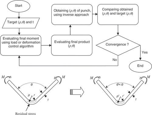
For inverse springback analysis of the free bending process, the initial configuration corresponding to desired ρ and θ is considered. The residual stress state is distributed on initial geometry. After applying the required moment for sheet bending that is evaluated from Equation (2), the inverse springback analysis would be carried out. The corresponding radius and angle of bending (ρ′, θ′) for the resulting desired radius and angle of bending (ρ, θ) could be obtained from process configuration at the end of inverse analysis. For evaluating the required bending moment and residual stress, forward analysis of the bending process is required. The process setting for this step is defined in a way that the desired radius and angle of bending (ρ, θ) results at the end of the loading step. Although the evaluated bending moment and residual stress are not exactly the same as the related results of designed process by inverse analysis, the difference is not considerable. If more precise results are required for the production of desired shape, moment and residual stress should be evaluated from designed configuration by inverse analysis (ρ′, θ′). The inverse algorithm is shown in .
Figure 1. Algorithm of inverse springback analysis for compensating springback error in V-bending process.
For investigating the convergence rate of inverse springback analysis, a program has been prepared for the analysis of the bending process by the theory of bending. Two algorithms are prepared for compensating springback error: the first one is based on a modification of the bending radius and angle in each iteration (direct method) and the second one is based on inverse springback analysis method.
3. Inverse finite element modelling of springback
By the adaptation of inverse springback analysis with FEM, complicated processes and three-dimensional processes could be analysed for compensating springback error.
The presentation of an algorithm for inverse springback analysis of three-dimensional process by using FEM is the main purpose of this section. There are two major steps in a sheet metal forming process: the loading and unloading steps. In most cases, displacement field of sheet in the loading step (Dl) could be obtained from die geometry and assigned punch displacement. The displacement field in the unloading step (Dsb) is due to the springback phenomenon. Obtaining the desired geometry at the end of unloading step, the sum of loading displacement and springback displacement should be equal to target displacement as follows:
(9)
where
are total displacement, loading displacement and springback displacement, respectively, at the optimum process for producing the target shape. Evaluation of
is not possible before performing or modelling the whole optimum process.
Inverse modelling of springback is a movement from final equilibrium state (end of unloading step) to middle equilibrium state (end of loading step). Therefore for efficient inverse modelling of springback, the required conditions for satisfying equilibrium should be considered.
3.1. Algorithm of inverse springback modelling by FEM
Two main subjects cause major problems in the convergence and accuracy of inverse modelling of springback. The former is unbalanced internal and external forces and the latter is large nodal rotation in the unloading step. The presented approach deals with these two subjects. Therefore, this approach is applicable for symmetric and asymmetric processes with a large amount of springback.
For inverse FEM modelling of springback, following steps should be adapted:
| • | The meshed part at the end of the forming process should be rebuilt. Defining the initial coordinates of nodes in flat sheet by | ||||
| • | The final stress state of the formed sheet (residual stress, | ||||
| • | Contact forces (Fc) between die and sheet (calculated from direct modelling) should be exerted on the created model, in an inverse loading step. | ||||
| • | One node, with minimum rigid body rotation, should be constrained. To find this node, nodal rotation in the unloading step is calculated for all nodes and the minimum value is obtained. | ||||
| • | Implicit analysis, considering nonlinear geometry and fixed direction of exerted forces, should be performed. | ||||
According to the virtual work principle, the internal work performed during inverse movement from the end of the process to the end of the loading step should be equal to the external work performed in the same period.
(12)
in which the internal work,
and external work,
could be obtained as:
(13)
(14)
where N, σ,
Ve, Fc, Γe and uf are the number of elements, stress function, final strain, element volume, external force vectors, boundary and nodal displacements at the boundary, respectively. In the inverse model, the residual stress could be considered as initial stress field. Therefore, the stress function could be represented as follows:
(15)
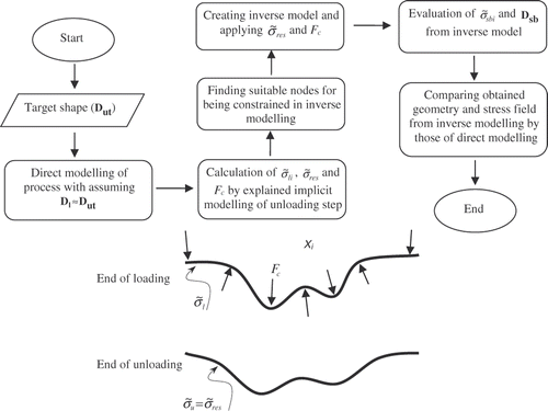
A brief algorithm and schematic model of inverse springback analysis is shown in .
3.2. Calculation of contact forces
As mentioned before, the most important factor that makes convergence and accuracy problems in inverse springback analysis (especially in asymmetric processes) is unbalanced contact forces between the die and work sheet. Therefore, the balanced contact forces have major importance in inverse springback modelling.
Modelling of sheet metal forming processes is usually performed by explicit FEM. Although explicit FEM has some advantages in convergence and solution time compared to implicit FEM, equilibrium in contact condition is not rigidly assigned in explicit contact modelling. Therefore, the calculated contact forces from explicit formulation does not satisfy the static equilibrium of the work piece.
In the modelling of symmetric problems, half of the geometry is usually modelled. Therefore, in symmetric processes the unbalanced contact forces affect the reaction forces at constrained nodes on symmetry axis. By this change of reaction forces at the constrained nodes, the static equilibrium of the whole model is satisfied, although the calculated contact forces are not the exact values. Therefore, inverse springback analysis with unbalanced contact forces is possible for symmetric processes, but has low accuracy due to the deviation of calculated contact forces from the exact values. For asymmetric problems, the unbalance of contact forces produces rigid body motion and causes the divergence of inverse springback analysis or great errors in the inverse calculated amount of springback.
According to the above algorithm, applying the inverse springback analysis with unbalanced contact forces in a compensating springback error algorithm results in a low convergence rate in symmetric problems and usually diverge in asymmetric problems Citation12.
In this article, an algorithm for the balancing of contact forces is presented by complex explicit–implicit direct modelling of the process. For balancing contact forces, in the direct analysis of the process, the following steps should be considered:
| • | Explicit modelling of the process until the end of the loading step should be performed. Penalty contact modelling is used in explicit modelling of the loading step. | ||||||||||||||||||||||
| • | The following objects from the work sheet should be read from explicit modelling of the loading step and be saved in a text file by a subroutine:
| ||||||||||||||||||||||
Implicit modelling of the unloading step should be performed in two substeps. These two substeps are as follows.
Substep 1:
An initial model that corresponds to the end of the loading step is created. For this purpose, coordinates of nodes are read from saved text file by a prepared subroutine. | |||||
Saved stress components in previous step are applied as initial stress state in the created model. | |||||
Saved interface nodes in previous step constrained in all three directional coordinates. | |||||
Performing an implicit analysis in this substep represents the balanced contact forces at the end of the loading step, because in implicit analysis static equilibrium is always satisfied.
Substep 2:
All constrained nodes in the previous substep are released. | |||||
One node is fully constrained. For convenience in inverse springback analysis, the obtained node in Section 3.1 is chosen. Choosing this node causes minimum rigid body rotation in the unloading step; therefore, the unloading step comprises springback deformation only. | |||||
Performing implicit analysis in this substep represents the final geometry of the work sheet after springback.
By applying the above algorithm for balancing the contact forces, the exact equilibrium of work sheet becomes available. Therefore, the inverse springback analysis becomes applicable for both types of symmetric and asymmetric processes. Also, by applying the search algorithm for minimum rotation nodes, the presented inverse approach is capable of springback analysis for processes with a large amount of springback.
3.3. Algorithm for compensating springback error
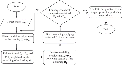
The presented algorithm can be used in an optimization algorithm to compensate springback error as follows:
| 1. | Target shape is considered as final product and the presented algorithm in Section 3.1 is applied to model springback inversely. The geometry obtained from the previous step is used for the configuration of die in next direct modelling. | ||||
| 2. | Final product of the previous step is compared to the target product. If the convergence limit is not achieved, next step should be followed. | ||||
| 3. | Step 1 is repeated by replacing parameters explained in Section 3.2 (contact forces, residual stresses, etc.) with those obtained in step 3. | ||||
| 4. | Steps 2–4 are repeated until the convergence criterion is satisfied and the final product corresponds to the target geometry at the desired tolerance. | ||||
The inverse algorithm for compensating springback error is shown in .
4. Results
For the investigation of the presented inverse approach, the symmetric V-bending and asymmetric bending processes are verified. For the V-bending process, the bending theory presented in Section 2 and inverse FE modelling presented in Section 3 are applied. For the asymmetric bending process, only inverse FE modelling is applied.
4.1. Inverse analysis of symmetric V-bending process
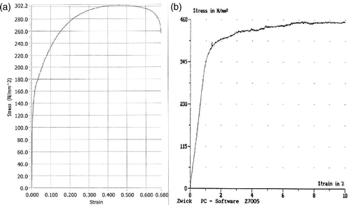
For this process, St-12 sheet with 1-mm thickness is applied. The obtained stress–strain curve from the tension test for the applied St-12 sheet is shown in . According to the obtained stress–strain curve, the hardening coefficient (K) and hardening exponent (n) in Equation (8) are calculated as 630 MPa and 0.337, respectively.
Figure 4. Stress–strain curve of applied sheets: (a) St-12 (thickness = 1 mm) and (b) annealed CK45 (thickness = 1 mm).
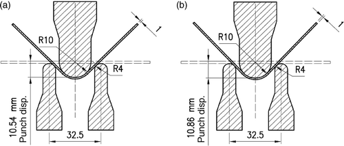
For the initial V-bending process, die settings are arranged to obtain 90° bending angle and 10.50 mm bending radius at the end of loading. Die settings for the initial test are shown in . This process is analysed by the bending theory given in Section 2. The obtained springback angle is 2.8° and the obtained bending radius after springback is 10.85 mm.
Figure 5. Die setting for (a) initial (90° bending) and (b) optimised (90° bending) V-bending process (dimensions are in millimeter).
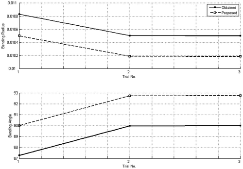
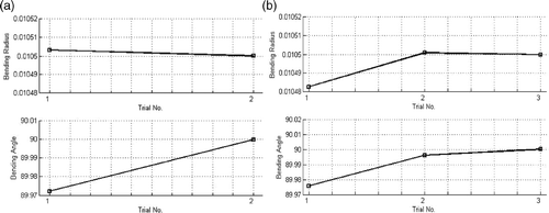
For achieving the die setting for the target bending angle of 90° and bending radius of 10.50 mm, the presented inverse algorithm shown in is applied. The inverse approach represents a final 90° bending angle and 10.50 mm bending radius in two trial steps for a definite precision. The forward procedure represents the desired results for the same precision in three trial steps. The convergence diagram of inverse and forward procedures is shown in . It can be seen that the inverse approach has a better convergence rate than the forward approach. The proposed angle and radius in each trial (obtained from the inverse approach) are shown in .
Figure 6. Convergence diagram for V-bending process: (a) inverse algorithm and (b) forward algorithm.
Applying the approach presented in Section 3.1, the inverse FE modelling of the above process is performed. Considering the bending angle as 90° and bending radius as 10.50 mm, the obtained springback angle is 3.5°. To verify the feasibility of this approach (), the inverse results are compared with the results of forward modelling.
Figure 8. Deformed shape at the end of loading and unloading steps: (a) forward analysis and (b) inverse analysis.
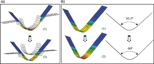
In , displacement field of 90° bending process at the end of the loading and unloading steps has been shown. At the end of the loading step (), the bending angle is set to 90°. The obtained bending angle at the end of the unloading step (after springback) is 93.5° (). More results have been presented in Citation25,Citation26.
By using the presented algorithm in Section 3.3, the die setting for producing 90° bending angle is obtained. The obtained die setting is shown in .
4.2. Inverse analysis of asymmetric bending process
The inverse analysis of the asymmetric bending process is performed on annealed CK45 sheet (thickness = 1 mm). As shown in , the bending die comprises of two parts with the same profiles. The gap between the die parts at the end of the loading state is set to sheet thickness.
Figure 9. Asymmetric bending results: (a) asymmetric bending die, (b) die profiles in each try and (c) convergence diagram.
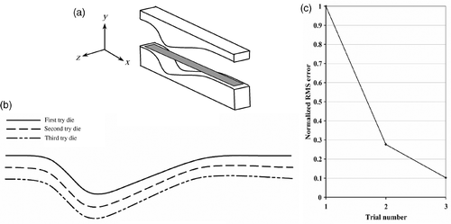
The proposed algorithm in is applied for compensating springback error in die shape design. The obtained die profiles from this algorithm are shown in . To investigate the convergence rate of this algorithm, the normalized root mean square (RMS) shape error is calculated for each try as:
(16)
where RN, Δyi, K and R0 are the normalized RMS, shape error of the ith point, number of points and RMS error for the first try, respectively. The shape error in the forming direction for 61 points is obtained. The convergence diagram of the inverse algorithm is presented in . The obtained product shape is compared to the target shape in .
As be seen in and , the obtained product from the third iteration is nearly identical to the target shape. The maximum shape error in Y direction is 0.1 mm.
4.3. Experiments
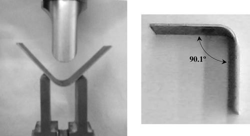
Two tests are arranged based on the obtained results from inverse FE modelling. In the first one, the V-bending process is performed on a St-12 strip with 1-mm thickness. The die setting is arranged according to the inverse FE results () to produce a 90° bend. The V-bending process and the obtained product are shown in . The obtained bending angle is 90.1°.
The second test is an asymmetric bending process of CK45 strip with 1 mm thickness. The obtained die profile from the third iteration () is applied to produce the desired die parts by a CAD/CAM machine. The asymmetric bending test is shown in . The obtained product is compared with the target geometry in . The shape errors for three random points are also shown in this figure. As can be seen, the shape error is negligible.
5. Conclusion
The inverse analysis of springback (starting from the final shape towards the end of the loading step) could have several advantages. The definite final shape of the work piece is the major advantage of this method.
In this article, by explicit–implicit FE modelling, inverse modelling of springback is presented and verified for asymmetric bending processes. By balancing the contact forces and minimizing the rigid body motion in this approach, the inverse springback analysis of asymmetric processes has been feasible. The efficiency and accuracy of this algorithm are verified for symmetric and asymmetric bending processes.
Applying the presented inverse approach in an optimization algorithm, tool design for compensating springback error becomes possible. Using this algorithm for symmetric V-bending and asymmetric bending processes, the efficiency and convergence of this approach is investigated. The results have shown a high convergence rate. The die shapes obtained from the presented algorithm are verified by performing two experiments. Products of tests and analysis are compared and high precisions resulted in both cases.
According to the obtained results, this approach could be applied in industrial tool design for symmetric and asymmetric sheet forming processes with a high convergence rate. The presented algorithms for the modelling of springback and optimizing its error are three-dimensional approaches; therefore, a wide range of sheet metal forming processes could be analysed and optimized by these algorithms.
References
- Cho, JR, Moon, SJ, and Kang, SS, 2003. Finite element investigation on springback characteristics in sheet metal U-bending process, J. Mater. Process. Technol. 141 (2003), pp. 109–116.
- Panthi, SK, Ramakrishnan, N, Pathak, KK, and Chouhan, JS, 2007. An analysis of springback in sheet metal bending using finite element method (FEM), J. Mater. Process. Technol. 186 (2007), pp. 120–124.
- Ling, YE, Lee, HP, and Cheok, BT, 2005. Finite element analysis of springback in L-bending of sheet metal, J. Mater. Process. Technol. 168 (2005), pp. 296–302.
- Gredeen, JC, and Chen, P, 1989. "Geometric mapping method of computer modeling of sheet metal forming". In: Proceedings of the 3rd International Conference on Numerical Methods in Industrial Forming Processes. Vol. 89. Fort Collins, CO: NUMIFORM; 1989. pp. 437–444.
- Mouatassim, MEl, Thomas, B, Jameux, JP, and Pasquale, EDe, 1995. An industrial finite element code for one step simulation of sheet metal forming. Presented at Proceedings of the International Conference on Numerical Methods in Industrial Forming Processes, NUMIFORM’95. Ithaca, NY, .
- Batoz, JL, Guo, YQ, and Mercier, F, 1998. The inverse approach with simple triangular shell elements for large strain predictions of sheet metal forming parts, Eng. Comput. 15 (1998), pp. 864–892.
- Naceur, H, Guo, YQ, and Batoz, JL, 2004. Blank optimization in sheet metal forming using evolutionary algorithm, J. Mater. Process. Technol. 151 (2004), pp. 183–191.
- Schmoeckel, D, and Beth, M, 1993. Springback reduction in draw-bending process of sheet metals, Ann. CIRP 42 (1993), pp. 339–342.
- Sunseri, M, Cao, J, Karafillis, AP, and Boyce, MC, 1996. Accommodation of springback error in channel forming using active binder force control: Numerical simulations and experiments, Trans. ASME, J. Eng. Mater. Technol. 118 (1996), pp. 426–435.
- Rosochowski, A, 2001. Die compensation procedure to negate die deflection and component springback, J. Mater. Process. Technol. 115 (2001), pp. 187–191.
- Liu, YC, 1988. The effect of restraining force on shape deviations in flanged channel, ASME J. Eng. Mater. Technol. 110 (1988), pp. 389–394.
- Gan, W, and Wagoner, RH, 2004. Die design method for sheet springback, Int. J. Mech. Sci. 46 (2004), pp. 1097–1113.
- Gan, W, Wagoner, RH, Mao, K, Price, S, and Rasouli, F, 2004. Practical methods for the design of sheet formed components, J. Eng. Mater. Technol. 126 (2004), pp. 360–367.
- Karafillis, AP, and Boyce, MC, 1992. Tooling design in sheet metal forming using springback calculation, Int. J. Mech. Sci. 34 (1992), pp. 113–131.
- Karafillis, AP, and Boyce, MC, 1992. Tooling design accommodating springback errors, J. Mater. Process. Technol. 32 (1992), pp. 499–508.
- Karafillis, AP, and Boyce, MC, 1996. Tooling and binder design for sheet metal forming processes compensating springback error, Int. J. Mach. Tools Manuf. 36 (1996), pp. 503–526.
- Cheng, HS, Cao, J, and Xia, ZC, 2007. An accelerated springback compensation method, Int. J. Mech. Sci. 49 (2007), pp. 267–279.
- L. Wu, C. Du, and L. Zhang, Iterative FEM die surface design to compensate for springback in sheet metal stampings, Proceedings of the International Conference on Numerical Methods in Industrial Forming Processes, NUMIFORM’95, Ithaca, NY, pp. 637–641, June 1995..
- E.L. Anagnostou, Optimized tooling design algorithm for sheet metal forming over reconfigurable compliant tooling, Proceedings of the International Conference on Numerical Methods in Industrial Forming Processes, NUMIFORM 2004, Vol. 712, Columbus, OH, pp. 741–748, June 2004..
- Lingbeek, R, Huetink, J, Ohnimus, S, Petzoldt, M, and Weiher, J, 2005. The development of a finite elements based springback compensation tool for sheet metal products, J. Mater. Process. Technol. 169 (2005), pp. 115–125.
- Kim, H, Nargundkar, N, and Altan, T, 2007. Prediction of bend allowance and springback in air bending, ASME J. Manuf. Sci. Eng. 129 (2007), pp. 342–351.
- Wagoner, RH, and Li, M, 2007. Simulation of springback: Through-thickness integration, Int. J. Plast. 23 (2007), pp. 345–360.
- Dongjuan, Z, Zhenshan, C, Xueyu, R, and Yuqiang, L, 2007. An analytical model for predicting springback and side wall curl of sheet after U-bending, Comput. Mater. Sci. 38 (2007), pp. 707–715.
- Kim, H, Nargundkar, N, and Altan, T, 2007. Prediction of bend allowance and springback in air bending, ASME J. Manuf. Sci. Eng. 129 (2007), pp. 342–351.
- Behrouzi, A, Mollaei, B, and Shakeri, M, 2008. A new approach for inverse analysis of springback in sheet bending process, J. Eng. Manuf. 222 (B) (2008), pp. 1363–1374.
- A. Behrouzi, M. Shakeri, and B. Mollaei, Inverse analysis of springback in sheet metal forming by finite element method, EngOpt 2008, International Conference on Engineering Optimization, Rio de Janeiro, Brazil, 1–5 June, 2008..
