Abstract
In this study, dynamic analysis and trajectory planning for a rigid-flexible manipulator is considered. The manipulator under consideration consists of two links–the first link is rigid while the second link is flexible. Euler–Bernoulli's beam theory is utilized to model the elastic link, where shear deformation and rotary inertia can be neglected if the cross-sectional area is small compared to the length of the beam. The tangential coordinate frame is employed to describe the elastic deflection of the flexible link. The equations of motion of the manipulator are derived using the extended Hamilton's principle. The joints trajectory will be designed based on four different trajectories and the joints torques required to move the end effector according to a prescribed trajectory will be obtained through the solution of the inverse dynamics problem. To validate the applicability of soft motion trajectory for flexible manipulators, a comparison with other standard trajectories is carried out for the first three mode shapes of vibration of the flexible link.
1. Introduction
The research interest in flexible manipulators, i.e. lightweight and large dimension robotic manipulators, has increased significantly in recent years. Major advantages of flexible manipulators include, but are not limited to; small mass, fast motion and large force to mass ratio, which are reflected in the reduced energy consumption, increased productivity and enhanced payload capacity Citation1. It should be noted that flexible manipulators have important applications in new and emerging fields, such as space exploration, manufacturing automation, construction, mining and maybe mine detecting in the near future.
The problem of modelling, trajectory planning and control of rigid-flexible manipulators has attracted many researchers in the past three decades. Manipulators with some flexible links, such as the rigid-flexible manipulators are attractive because they avoid the severe control problems associated with conventional manipulators when they operate at high velocities. Typically, conventional manipulator links are designed to be modelled as rigid ones by having large masses and mass moment of inertias, which result in large inertia forces. On the other hand, rigid-flexible manipulators can be optimized to reduce the mass of the outermost links from the fixed point of the motion. For more details about the contribution in this area, the reader is referred to the recent review article Citation2.
Low and Vidyasagar Citation3 considered a two-link manipulator with only the last link as a flexible member and used the Lagrangian method to study its dynamics. Controller design for a rigid-flexible two-link manipulator is considered by Yigit Citation4. It has been shown that the stability of independent joint proportional-derivative (PD) control does not depend explicitly on the system parameters. No discretization or linearization of the equations of motion is required to assure the stability. Simulation studies also show that independent joint PD control gives reasonably good results for the flexible system, and is robust to parameter uncertainties. Dogan and Iftar Citation5 carried out the modelling and control of a two-link robot manipulator, whose first link is rigid and the second link is flexible. They applied the extended Hamilton's principle to obtain the equation of motion and the corresponding boundary conditions. A composite controller based on the singular perturbation method is designed in their work. Shi et al. Citation6 derived a mathematical model governing the dynamics of a constrained rigid-flexible manipulator moving in a horizontal plane using Hamilton's principle. The state vector of the proposed controller consists of joint angle of the rigid link, its derivative and integral, the first deflection mode and its derivative and the integral of contact force. A multivariable controller is proposed for the simultaneous motion and force control of the manipulator. Computer simulation results show that their proposed controller is capable of performing the straight line tracking task satisfactorily under four different conditions.
De Luca and Di Giovanni Citation7 considered the problem of finding the torque commands that provide a rest-to-rest motion of a two-link rigid-flexible manipulator with a flexible forearm (FLEXARM). The nominal rest-to-rest torque is obtained by standard inverse dynamics computation. Numerical results are presented and a possible extension is discussed. Ata and Johar Citation8 derived a dynamic model with zero tip deformation constraint using the extended Hamilton's principle. An analytical approach for the vibration of the flexible link is presented using the assumed modes method. The effect of changing both the joint motion profile and the shape of the compliant surface on the force exerted at the end-effector and the required rigid and flexible torques is investigated. An optimal path planning for a two-link rigid-flexible manipulator to suppress the residual vibration is presented by Akira Citation9. The flexible link is modelled by considering the axial displacement, due to large bending deformation, based on inextensibility condition. The Lagrangian approach in conjunction with the assumed modes method is applied to derive the equation of motion of the manipulator. The joint angle is represented by cubic-spline function and then a particle swarm optimization to find an optimal path, which has minimum vibration requirement.
In this study, dynamic modelling and trajectory selection for a rigid-flexible manipulator is considered. The equations of motion are derived using the extended Hamilton's principle. Four different trajectories are considered and the resultant actuator's torques are obtained for the two joints by solving the inverse dynamics problem.
2. Mathematical modelling
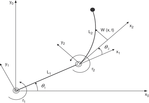
Consider the flexible robot shown in , which consists of a first rigid link of mass m, length L1, moment of inertia I1 and a second flexible link with mass density ρ2, length L2 and flexural stiffness EI. The first rigid link forms an angle θ1 with the horizontal, while θ2 represents the angle between the second link and the tangent to the flexible link at the proximal end. The elastic deflection w(x,t) can be measured from the tangent to the flexible link at the proximal end. Longitudinal deformations are neglected and it is assumed that Euler–Bernoulli's beam theory is adequate to describe the flexural motion of the second link. The manipulator is assumed to move in the horizontal plan, so the gravitational effect can be neglected and no damping is considered.
For kinematics analysis, rotating frames will be attached with each link as shown in . The position vector r of any point on the flexible link can be described as
(1)
(2)
where the spatial coordinate x indicates the position of the undeformed point on the elastic link. The total kinetic energy of the system can be given as
(3)
where I1 is the total inertia of the first link with respect to the shoulder joint axis; mh and Ih are the mass inertia of the rigid hub with respect to the elbow joint, respectively. The potential energy is represented by the strain energy, which can be given as
(4)
The equations of motion can be derived by applying the extended Hamilton's principle which states:
(5)
where L = KE−PE and
, in which L is the Lagrangian of the system and δW represents the non-conservative work done by the joint actuators, τ1 and τ2, at the shoulder and elbow joints, respectively. After some algebraic manipulation, the Lagrangian of the system can be given as
(6)
Upon substituting Equation (5) into Equation (4) and after some algebraic manipulation one can get the equations of motion for the first and second links as
(7)
(8)
The equation for the elastic deflection of the second link is given by
(9)
The flexible beam has many combinations of boundary conditions and therefore, the selection mode shape depends on selected boundary conditions accordingly. As an illustration, the beam is subject to the fixed-free boundary conditions, Citation10–13 which can be expressed as
(10)
Note that the axial deformations are not considered here. For the beams considered here, axial deformation does not include significant axial vibrations Citation10.
Basically, analytic solution for Equation (8) subject to the fixed-free boundary conditions (9) is very difficult since it is heavily nonlinear. As there is no analytical method available for the solution of differential equations, the problem is solved by numerical simulation Citation14. An alternative approach is to approximate the solution using the general form of the lateral vibration equation from the flexible beam theory Citation15.
The equation of motion for the forced lateral vibration of a non-uniform beam is
(11)
For a uniform beam, the general equation for flexural vibration can be written as Citation16
(12)
For free vibration, f (x, t) = 0 and so the equation of motion becomes:
(13)
where
(14)
Then, the transverse displacement is found using the method of separation of variables, which can be expressed as
(15)
where W(x) is a function of the spatial coordinate (x) and is known as the normal mode or characteristic function of the beam, T(t) is the time function and i denotes the number of the mode shape. For any beam, there will be an infinite number of normal modes with one natural frequency associated with each normal mode Citation16. The solution for Equation (8) subject to the boundary conditions (9) can be expressed in the following form Citation17:
(16)
where
in which ωn is the natural frequency.
The time function T(t) is the solution of the simple harmonic equation given by
(17)
where A and B are constants to be determined from the initial conditions. The coefficient A represents the initial displacement x0, while the coefficient B represents the initial velocity of the beam.
3. Trajectory planning
The most common techniques for trajectory planning for industrial robots are polynomial of different orders, cubic and B-splines, linear segments with parabolic blends (LSPB) Citation18 and the soft motion (SM) trajectory Citation19. The LSPB trajectories are faster and more suitable for industrial applications. On the other hand, the higher order polynomials trajectory as well as the SM trajectory are easy to design and control especially for the jerk. They are accurate and precise and they are suitable for medical applications. The SM trajectory has the extra advantage of controlling the jerk at the initial stage and goal of the task. In this article, the trajectory planning for each joint is designed using four different trajectories, third- and fifth-order polynomials, LSPB and SM trajectories. These trajectories represent rest-to-rest manoeuvring where the link starts from rest, increases gradually and stops at the end of the trajectory. All trajectories also have the same initial and final values for the joint angles, but they have different acceleration profiles.
3.1. Polynomial of different orders
3.1.1. Third-order trajectory
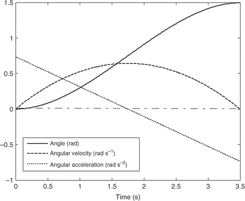
The third-order polynomial trajectory is the simplest polynomial, which controls the initial and final angular velocities. In this case, the total number of boundary conditions is four, allowing the designer to control only the angular velocity at start and goal positions. The trajectory is given by
(18)
in which C0, C1, C2 and C3 are the coefficients to be determined from the initial conditions.
The initial conditions that will be assumed to derive the four trajectories are
where θi and θf are the initial and final values of each joint,
and
are the initial and final angular velocities of each joint, tf is the duration time,
is the maximum angular velocity and Jmax is the maximum allowable jerk.
represents the angular position, angular velocity and angular acceleration for the two joints.
3.1.2. Fifth-order polynomial trajectory
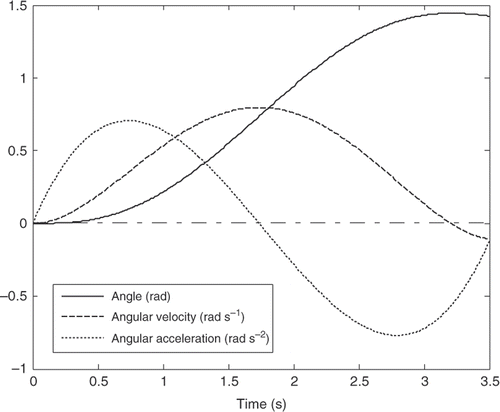
Unlike the third-order polynomial trajectory, which controls the initial and final angular velocities, the fifth order takes into account starting and ending accelerations. In this case, the total number of boundary conditions is six, allowing a fifth-order polynomial to control the angular acceleration at start and goal positions. The trajectory is given by
(19)
in which C0, C1, C2, C3, C4 and C5 are the coefficients to be determined from the initial conditions. represents the angular position, angular velocity and angular acceleration for both the joints.
3.1.3. Linear segment with parabolic blends
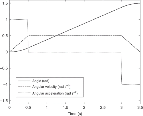
The LSPB trajectory represents one of the most common trajectories in industrial robotic applications. The joints move with maximum angular speed and zero angular acceleration during most of the time interval representing trapezoidal velocity profile. It has an advantage of controlling the angular acceleration at the start and goal positions. The trajectory is composed of three main parts as shown in where is the blending time, ω is the angular velocity and C2 is the desired angular acceleration. represents the angular position, angular velocity and angular acceleration for the two joints.
Table 1. LSPB trajectory's parameters.
3.1.4. SM trajectory
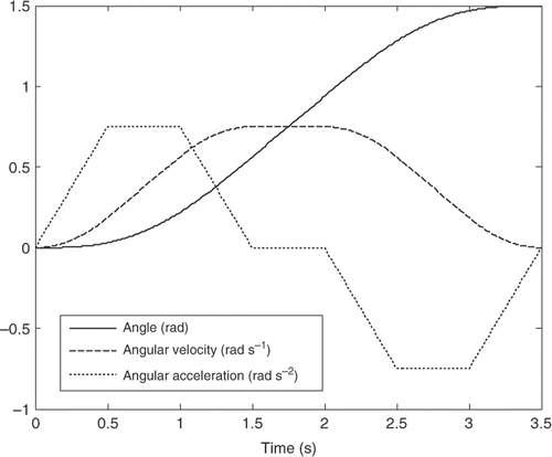
The SM trajectory, as introduced by Herrera and Sidobre Citation19, is a seven cubic equations trajectory to obtain a smooth motion in robot service application; it is also an effective tool to reduce the jerk and to control the motion of a moving object smoothly and accurately. The soft trajectory starts by calculating maximum jerk at the beginning of the trajectory then continues, by applying boundary conditions, and finds the corresponding angle, angular velocity and angular acceleration for the different segments of the path. The time interval is divided into seven segments, each of which has its own characteristics.
The parameters of the seven segments SM trajectory are summarized as shown in Citation18 where are the jerk, angular acceleration, angular velocity and angle, respectively. The relation between the final time and the time of each segment can be written as
(20)
and the maximum jerk can be determined by
(21)
Table 2. SM trajectory's parameters.
represents the angular position, angular velocity and angular acceleration for the two joints.
4. Simulation
The main objective of this study is to calculate the actuator's torques required to move the robot joints through a prescribed trajectory. These torques will be calculated using the solution of the inverse dynamics problem based on four different trajectories to select the best trajectory for the rigid-flexible manipulator in the joint space. The position and orientation of the end effector can be obtained through the forward kinematics by substituting into Equations (1). The simulation analysis will be carried out using MATLAB, where a code is written as m-file and consists of three blocks that are connected in series:
| 1. | The first block is the elastic deflection block, which is responsible for solving Equations (15) and (16) to find the first three modes of vibration w(x, t) of the flexible link for the fixed-free boundary condition. | ||||
| 2. | The second block is the trajectory generation block, which is responsible for generating the four different trajectories, third and fourth-order polynomials, the LSPB trajectory and the SM trajectory offline. These trajectories are generated offline and the trajectory generation block ensures that all trajectories satisfy the same constraints for angular position, velocity and acceleration. The input to this block is the trajectory constraint and the output is a time function representing the trajectory from start to goal where the coefficients are calculated automatically. | ||||
| 3. | The third block is the torque generation block which applies the information from the previous two blocks and substitutes the obtained data into Equations (7) and (8) to calculate the required actuator's torques for both the joints. This will be carried out for the first three mode shapes of vibration of the flexible link for each trajectory. | ||||
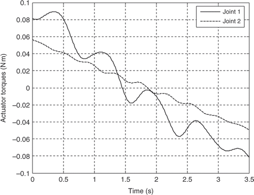
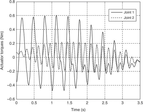
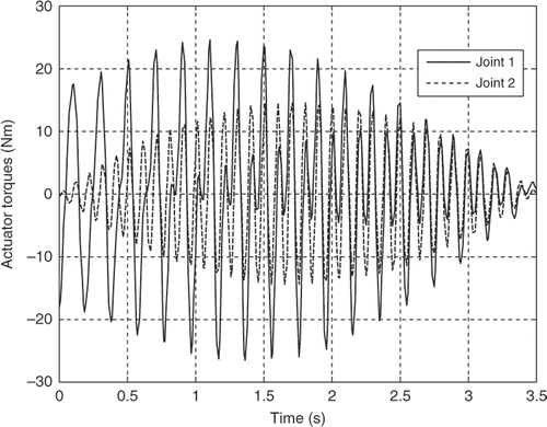
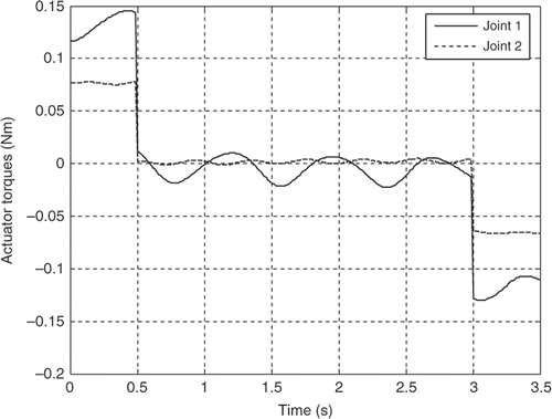
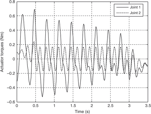
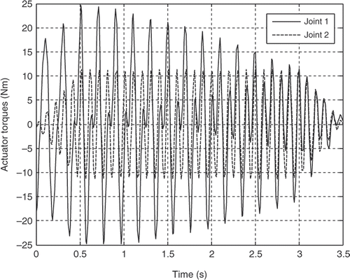
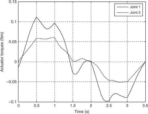
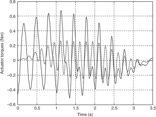
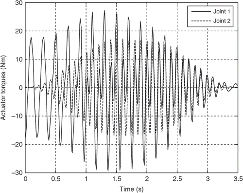
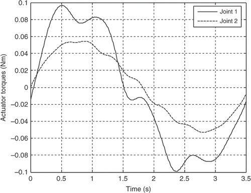
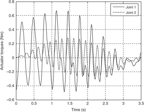
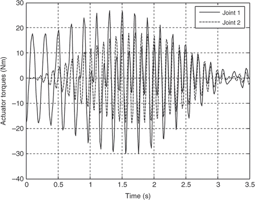
The robot parameters employed in this simulation analysis are listed in . The resultant actuator's torques for both the joints for the first three mode shapes of vibration of the flexible link are illustrated in Figures for the third-order polynomial, Figures for the LSPB, Figures for the SM trajectories and Figures for the fifth-order polynomial trajectories, respectively.
Table 3. Robot parameters for simulation.
5. Discussion and conclusions
It can be observed clearly from the simulation results that the joint accelerations have great contribution on the actuator's torques for all trajectories. Although the initial and final values for the joints angles are the same and the assumption of rest-to-rest manoeuvring is applied for the four trajectories, the actuator's torques are completely different based on the acceleration profile of each trajectory. The peak values are more or less within the range and the flexibility effect appears clearly through the resultant fluctuations in all torque profiles for the first three mode shapes of the flexible link.
For the first mode, the actuator's torques using the third-order polynomial and the LSPB trajectories have in common initial and final values, which may excite the system especially at the start and goal positions. On the other hand, the calculated torque using the fifth-order polynomial and the SM trajectories almost starts from rest and ends at rest, which can be considered an advantage over the other two trajectories mentioned previously.
The torque profile using the fifth-order polynomial and the SM trajectories have almost the same trend and there is no significant difference of the SM trajectory over the fifth-order polynomial in that sense. The main advantage of the SM trajectory is controlling the jerk, which enhances the utilization of flexible manipulators in many tasks. For the fifth-order polynomial trajectory, it is possible to control only the initial and final accelerations and not the jerk. To control the jerk, one has to go for seventh-order polynomial. On the other hand, the fifth-order polynomial represents the whole trajectory with one piece of continuous function, while the SM trajectory requires seven third-order polynomials to represent the same trajectory. This can be a possible advantage for the fifth-order polynomial, since the actuator's torques are almost the same.
On the other hand, comparison between the torque profiles for the LSPB and the SM trajectories shows that the SM trajectories results in less peak values, smoother torque profile and zero starting torque Citation20. So the SM trajectory can replace the LSPB trajectory in industrial robotics applications.
References
- Fei-Yue, W, and Yanqing, G, 2003. Advanced Studies of Flexible Robotic Manipulators: Modeling, Design, Control and Applications. Singapore: World Scientific Publishing; 2003.
- Dwivedy, SK, and Eberhard, P, 2006. Dynamic analysis of flexible manipulators, a literature review, Mech. Mach. Theory 41 (2006), pp. 749–777.
- Low, KH, and Vidyasagar, M, 1988. A Lagrangian formulation of the dynamic model for flexible manipulator systems, ASME J. Dyn. Syst. Meas. Control 110 (1988), pp. 175–181.
- Yigit, AS, 1994. On the stability of PD control for a two-link rigid-flexible manipulator, J. Dyn. Syst. Meas. Control 116 (1994), pp. 208–215.
- A. Dogan and A. Iftar, Modeling and Control of a Two-Link Flexible Robot Manipulator, Proceedings of the 1998 IEEE International Conference on Control Applications, Trieste, Italy, Vol. 2, pp. 761–765, 1998..
- Shi, ZX, Fung, EHK, and Li, YC, 1999. Dynamic modeling of a rigid-flexible manipulator for constrained motion task control, J. Appl. Math. Model. 23 (1999), pp. 509–525.
- A. De Luca and G. Di Giovanni, Rest-to-Rest Motion of a Two-Link Robot with a Flexible Forearm, Proceedings of the IEEE/ASME International Conference on Advanced Intelligent Mechatronics, Como, Italy, pp. 929–935, 2001..
- Ata, AA, and Johar, H, 2005. Dynamic analysis of a rigid-flexible manipulator constrained by arbitrary shaped surfaces, Int. J. Model. Simul. 25 (2005), pp. 259–268.
- A. Akira, Trajectory planning for residual Vibration Suppression of a Two-Link Rigid-Flexible Manipulator, Dynamics and Design Conference, Japan, p. 514, 2006..
- Yigit, AS, 1992. A robust controller for a two-link rigid-flexible manipulator, Trans. ASME Adv. Rob. DSC- 42 (1992), pp. 229–234.
- Matsuno, F, Asano, T, and Sakawa, Y, 1994. Modeling and quasi-static hybrid position/force control of constrained planar two-link flexible manipulators, IEEE Trans. Robot. Autom. 10 (1994), pp. 287–291.
- Theodore, RJ, and Ghosal, A, 1997. Modeling of flexible-link manipulators with prismatic joints, IEEE Trans. Syst. Man Cybern. Part B Cybernet. 27 (1997), pp. 296–305.
- J. Fei, Active Vibration Control of Flexible Steel Cantilever Beam using Piezoelectric Actuators, Proceedings of the 37th Southeastern Symposium on System Theory SSST'05, Tuskegee, AL, pp. 35–39, 2005..
- A. Mohri, P.K. Sarkar, and M. Yamamoto, An Efficient Motion Planning of Flexible Manipulator along Specified Path, Proceeding of the IEEE International Conference on Robotics and Automation, Leuven, Belgium, pp. 1104–1109, 1998..
- Hu, FL, and Ulsoy, AG, 1994. Dynamic modeling of constrained flexible robot arms for controller design, Trans. ASME, J. Dyn. Syst., Meas. Control 116 (1994), pp. 56–65.
- Meirovitch, L, 1967. Analytical Methods in Vibration. New York: Macmillan; 1967.
- Rao, SS, 1995. Mechanical Vibrations, . Reading, MA: Addison-Wesley; 1995.
- Ata, AA, 2007. Optimal trajectory planning for manipulators: A review, J. Eng. Sci. Technol. 2 (2007), pp. 32–54.
- I. Herrera, and D. Sidobre, On-Line Trajectory Planning of Robot Manipulator's End Effector in Cartesian Space using Quaternions, 15th International Symposium on Measurement and Control in Robotics, Belgium, 2005..
- A.A. Ata and M. Sa’adeh, Soft Motion Trajectory for Planar Redundant Manipulator, The 9th International Conference on Control, Automation, Robotics, and Vision (ICARCV 2006), Singapore, pp. 1514–1519, 2006..
