Abstract
The evaluation of the physical conditions of a hollow metal cylindrical structure is critical in many applications, such as those involving oil or power generating industries or water pipeline networks. Direct and internal inspection is often not possible or highly costly in terms of time and inspection tools. We present here a guided waves-based technique whose particularity is to detect and to quantify a circular anomaly inside a hollow metal cylindrical structure, while being deployed. The technique requires only one measurement point to obtain information on remote sections that are hundreds of metres apart. Radar equipment sends an electromagnetic wave through an open end of the structure and it receives the backscattered field, which is produced by variations of the internal hollow structure radius (deformations, welding joints, etc.). We derive the link between the recorded signal, which carries information on amplitude and propagation time, the circular anomalies parameters, defined by the percent radial reduction, rap, and the deformation length, la, avoiding the complications of the most classification algorithms. The anomaly identification is obtained through an inversion procedure that performs well with both the synthetic and real data. In the latter case, the estimated parameters of a given anomaly ( = 4.9%,
= 3.85 m) are in good agreement with the actual ones (rap = 5%, la = 3 m).
1. Introduction
The integrity of a hollow metal cylindrical structure is critical in many applications, i.e. power or oil generating industries or water pipeline networks, where proper inspection and maintenance is a demanding task, utilizing techniques such as direct assessment methods, hydrostatic testing and internal inspection tools. Direct assessment methods imply visual and physical (internal and external) observations; hydrostatic testing involves pressuring the structure to a level equal to or above its normal operating pressure; internal inspections are run with sophisticated technological tools (i.e. robots) that, moving along the structure, detect point-by-point loss of metal and, in some cases, deformations. The operators generally use a combination of direct assessments, internal inspection tools and/or hydrostatic tests for ensuring the integrity of the whole structure Citation1. In the last few decades, to overcome those difficulties and to save time, various non-destructive techniques were developed, among those based on the wave propagation in hollow cylinders Citation2, both empty and filled. Published works report on ultrasonic wave analysis to detect and classify defects and deformations Citation3–10. In another approach, defect classification is based on the identification of the signal features that are sensitive to the defect in the time domain and/or in the frequency domain by using numerical techniques and classification algorithm jointly Citation11.
We introduce here an indirect method for the evaluation of the physical condition of a metal cylindrical hollow structure by using electromagnetic waves that let us inspect the structure while being deployed up to distances of hundreds of metres. We restrict our study to a structure composed of the elements of known length, welded together, and we are interested in the detection of cylindrical deformations. Radar equipment sends a source signal through an open end of the structure and it receives the backscattered wave. Metal cylindrical axial sections are modelled as dispersive transmission channels. According to the theory of time domain reflectometry (TDR), the electromagnetic propagation along non-uniform transmission lines gives rise to transmission–reflection effects not present in a uniform structure Citation12. We use these effects to detect and to characterize any possible anomaly. The reflections produced by circular anomalies are unpredictable and their amplitude can be very low, depending on the extension and on the magnitude of the deformation. On the other hand, experimental data show that the joints between the cylindrical elements produce detectable reflections that can be easily modelled. So, instead of looking directly for the reflections from the anomalies, we look for the modifications of the reflections from the joints with respect to the reference (uniform structure) reflections. In fact, a deformation of a cylindrical element modifies the reference electromagnetic propagation constant, which in turn produces a modification in the reference signal transmitted through the element. Indeed, a source could excite all the modes which propagate in the system operating frequency bandwidth. That is why the experimental setup was designed to have the bandwidth of the dominant propagation mode. This let us develop a single mode model as the converted modes, that could possibly result from the discontinuities, are with negligible power compared to the dominant one.
We have studied and realized a simulator that computes the electromagnetic response of a hollow cylindrical structure including a circular anomaly: model parameters are the geometry of the elements and of the deformation. Anomaly detection is performed through an inversion procedure, whose objective is to fit the backscattered signal due to the joints (input) with the simulator output, for varying length and depth of a circular anomaly. We have tuned and optimized the procedure on synthetic data. Then, we have validated the system on real data acquired in a test site under controlled conditions.
Section 2 shows the TDR model. Section 3 describes the modelling of the circular anomaly, i.e. the calculation of the specific phase constant of a deformed metal cylindrical hollow structure, as a function of the circular anomaly parameters. Section 4 describes the inversion procedure, i.e. the estimation of the properties of a circular anomaly inside a hollow metal cylindrical structure. Section 5 shows the detection results on synthetic and real data. Conclusions and perspectives are drawn in Section 6.
2. TDR model
We assume in the following that
| 1. | the hollow metal cylindrical structure is made up of elements of equal length l and radius r, welded together; | ||||
| 2. | a section of the structure is composed by one or more consecutive elements; | ||||
| 3. | the welded joints produce a reflected signal described by a scalar (reflection coefficient), while their effect on the transmitted signal can be neglected and | ||||
| 4. | a circular anomaly is a constant and abrupt reduction of the internal radius inside one section. | ||||
We define a curvilinear axis x along the structure. The opening of the structure is at coordinate x0. The nth junction is at coordinate xn (). The input signal is a wavelet w(t, x0), where t is the observation time (s), generated at the open end of the structure. The signal at the distance xn, s(t, xn), is given by the convolution of the transmitted wavelet w(t, x0) with the channel impulse response h(t, x0 xn),
or in the frequency domain,
where f is the frequency (Hz).
The global channel transfer function between the coordinates x0 and xn, H(f, x0, xn) can be written as follows:
with A(f, x0, xn) and B(f, x0, xn) the corresponding magnitude and phase.
H(f, x0, xn) can be factorized in the product of the n transfer functions of the structure elements,
where A(f, xi, xi + 1) and B(f, xi, xi + 1) are, respectively, the magnitude and the phase of H(f, xi, xi + 1). Similarly, A(f, x0, xn) and B(f, x0, xn) can be factorized as follows:
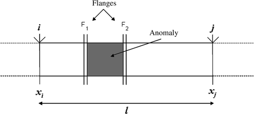
For a generic section between the joints at coordinates xi and xj, with xi < xj (), we have
or in the frequency domain,
The magnitude A(f, xi, xj) and the phase B(f, xi, xj) of H(f, xi, xj) are functions of the specific attenuation α(f) (Np m−1) and of the phase constant β(f) (rad m−1), both depending on the frequency Citation13
(1)
(2)
with ls = xj - xi the section length.
The transfer function of the section can be estimated by the spectral ratio
A small anomaly in the section mainly affects the phase of the transfer function and we can observe the section integrity by measuring the specific phase constant. In practice, we record the reflections sobs(t, xj) and sobs(t, xi) (subscript ‘obs’ stands for the observed data) from the joints at positions xj and xi, and we compute
(3)
where the angle symbol ∠ represents phase.
Equation (3) is the key to the anomaly identification, provided we have the relations between the phase constant and the geometrical and electromagnetic parameters of the anomaly. These relations will be derived in the following section.
3. Circular anomaly in a hollow cylindrical structure
We analyse the effects on the electromagnetic propagation parameters of a circular anomaly in a hollow metal cylindrical section modelled as a circular waveguide. The determination of the propagation constant in a circular waveguide surrounded by a medium with infinite conductivity is well known. Here, we are interested in a solution that works: (a) for external medium with finite conductivity; (b) near the cut-off region and (c) with accurate approximation and low computational cost. Hence, the propagation constant is derived from the characteristic equation through a perturbation technique developed expressly. We consider a small anomaly so that only the phase constant β(f) is affected. We briefly remind the main results, while the reader is referred to Citation14 for details.
3.1. Specific phase constant of metal cylindrical hollow structures
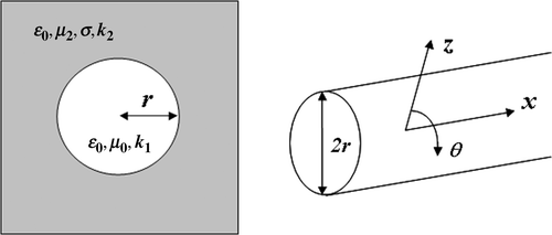
Let us consider a hollow circular cylinder of a radius r and of infinite length, surrounded by a dissipative medium of finite conductivity (). k1 is the propagation constant of the internal medium with permittivity ε1 = ε0 and permeability μ1 = μ0; k2 is the propagation constant of the external medium with finite conductivity σ2, permittivity ε2 = ε0 and permeability μ2 = μr2μ0.
Under the assumption of single mode model (Section 1) and among the four types of normal modes that occur in such a cylinder, we inspect the hybrid electric mode HE11 which is the dominant one. Its propagation constant γ11 can be calculated by solving the simplified characteristic equation Citation14
through a perturbation technique to single out the equation's roots
As long as the HE11 mode is of interest, we obtain
(4)
(5)
(6)
(7)
where ν11 can be approximated as
The phase constant β is the imaginary part of γ11, easily computed by solving Equation (7)
(8)
3.2. Model of the anomaly in a cylindrical hollow structure
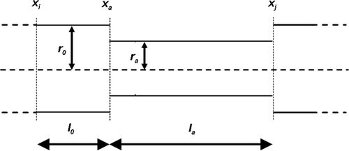
We can divide a deformed section delimited by the joints in position xi and xj, in two subsections: a regular one (xi < x < xa) and a deformed one (xa < x < xj). The coordinate xa defines the starting position of the anomaly (xi < xa < xj).
The anomaly profile is defined by the percent radial reduction as follows:
(9)
where r0 and ra(x) are the nominal radius of the structure and the reduced one, respectively, that can vary along the x direction.
Since we are looking for the transmission effects, we can approximate the anomaly in a section of the structure as a constant radial reduction ().
In this case, the properties of the anomaly are its length (la), and the constant percent radial reduction of the deformed subsection (rap), so that Equation (9) becomes
(10)
with ra the value of the reduced radius.
The global section transfer function H(f, xi, xj) can be factorized in the product of the regular and of the deformed subsection transfer functions,
Going to amplitude and phase representation,
We can express A(f, xi, xa) and B(f, xi, xa) in terms of the specific attenuation α0(f) (Np m−1) and of the phase constant β0( f) (rad m−1) of the regular subsection
(11)
(12)
with l0 = xa−xi the regular subsection length.
Similarly, A(f, xa, xj) and B(f, xa, xj) can be expressed in terms of the specific attenuation αa(f) (Np m−1) and of the phase constant βa(f) (rad m−1) of the deformed subsection
(13)
(14)
with l0 = xj−xa the deformed subsection length.
The global section transfer function H(f, xi, xj) becomes
From Equations (1), (11) and (13) we obtain
(15)
From Equations (2), (12) and (14) we obtain
(16)
We want now to relate the phase constant in Equation (16) with the anomaly radius, length and electromagnetic parameters. β0(f) is computed from Equation (8) by substituting the radius r with the nominal radius of the regular subsection, r0. Then, using Equations (8) and (10), it is possible to link explicitly the phase constant of the deformed subsection, βa, to the percent radial reduction, rap
(17)
Finally, β(f) can be calculated from Equations (16) and (17) as follows:
(18)
For the sake of simplicity, we have omitted the frequency dependence of β, β0, v11 and k1 in Equation (18).
4. Inversion procedure
The detection procedure iteratively analyses the reflections of the welded joints in order to infer the transmission properties of each structure element.
In the first step, we extract the echoes of the joints delimiting the section during the analysis from the backscattered signal. This task can be achieved by converting the known position of the joints (spatial coordinate) into the two-way travel time domain (time coordinate), using a reference propagation velocity. Then, we compute the spectra of the echoes and, from Equation (3), the phase constant βobs(f). Finally, we obtain the parameters of the anomaly by inverting Equation (18), in the bandwidth of the signal. The input of the inversion procedure is the observed data βobs (f) and the outputs are the length la of the anomaly and the percent radial reduction rap.
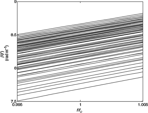
The presence of the product term βa(f) · la in Equation (18) leads to a non-linear inversion. Due to the strong non-linearity of the inverse problem, we estimate the anomaly parameters through an exhaustive search technique. We pre-calculate by means of Equation (18) a look-up table with K different phase curves βi(f) (i = 1, …, K): each curve corresponds to a pair (la, rap)i of the anomaly. shows an example of a lookup-table with different curves βi(f).
Figure 5. Lookup-table with different curves βi(f) for different pairs (la, rap)i. Note: la varies from 0 to 12 m with steps of 1 m; rap varies from 0% to 10% with steps of 1%. The curves are not equally spaced and the mapping is strongly non-linear.
The minimization of the L2 norm of the distance between the observed data βobs(f) and βi(f) gives the recalculated data and the estimated model parameters
Citation15. Analytically
In practice, the inversion is applied on a discrete and finite set of frequencies and the inverse problem can be formulated in matricial form.
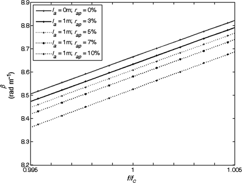
It is interesting to analyse the behaviour of the βi(f) curves for different values of the section length ls. and show the curves for ls = 12 and ls = 24 m, respectively. We observe that for increasing ls, there is a compaction of the curves, so that their relative distances decrease: the inversion procedure becomes more sensitive to noise and it could output inaccurate solutions. This suggests us to consider the minimum available section length.
Figure 6. βi(f) curves as a function of normalized frequency, for some (la, ra)i pairs. Section length ls = 12 m.
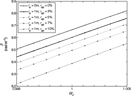
Figure 7. βi(f) curves as a function of normalized frequency, for some (la, ra)i pairs. Section length ls = 24 m.
The solution of this inverse problem is intrinsically not unique as different pairs could give the same βi(f) curve. The lack of uniqueness has been overcome by pre-computing the lookup-table with a discretization step which ensures that the solutions that differ numerically result in the same physical solution.
5. Examples
The inversion procedure is validated on synthetic and real data.
5.1. Synthetic data
We test the detection procedure on a synthetic data set. We consider a realistic structure composed of elements of length ls = 12 m, welded together. The section located between the coordinate xi = 24 and xj = 36 m has a radial reduction (circular anomaly) for a portion of its total length ls = 12 m. We consider two cases: (a) the absence of anomaly and (b) the circular anomaly of radial reduction rap = 3% and length la = 2 m. We simulate the transmission of a typical band-pass signal Citation16, around a proper carrier frequency, fc, inside the hollow metal cylindrical structure. We propagate the signal taking into account: the backscattering effects due to the joints, for both cases (a) and (b); the variations in the transfer function of the structure due to the presence of the anomaly to detect, in case (b) only.
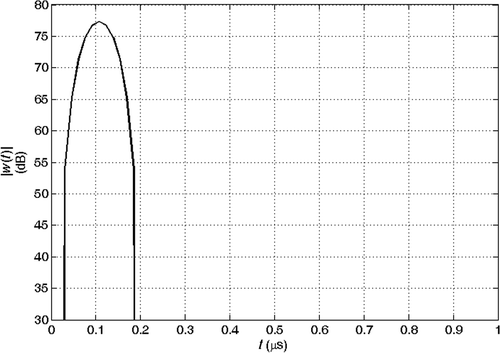
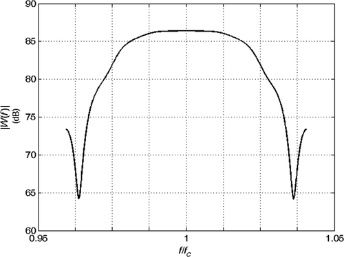
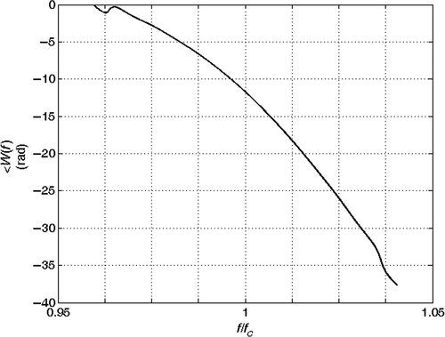
is the absolute value of the transmitted signal at x = 0 m, i.e. before its propagation in the section, as a function of time. and are the magnitude and the phase of the corresponding frequency spectrum.
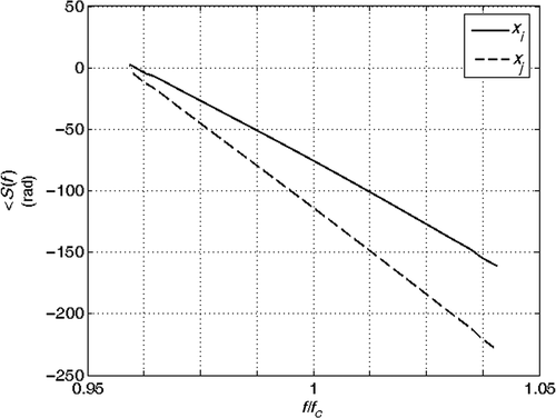
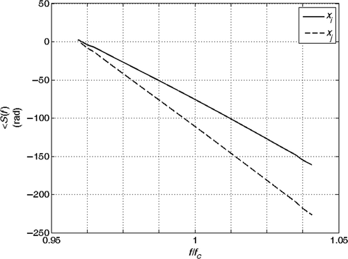
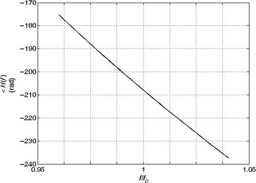
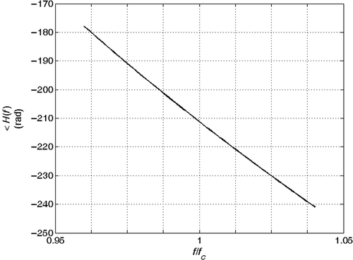
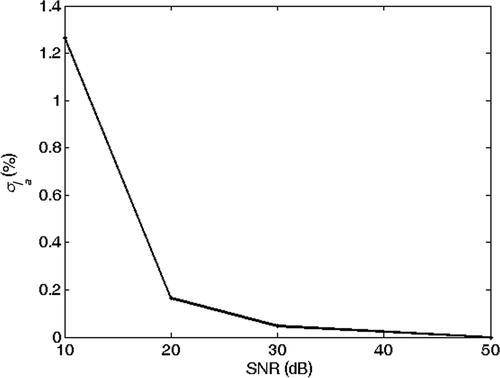
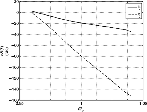
and show the echoes (absolute value) from the joints at coordinates xi and xj for the two cases (a) and (b). Here we assume that the echoes of the joints during the analysis do not interfere with the echoes from other joints. This assumption is confirmed also by experimental results. and show the phase of the spectrum of the echoes during the analysis and and are the phase of their ratio, which is proportional to βobs(f). The solution of the inverse problem is reported in : in the absence of noise, the estimated model is the exact model. We then performed the inversion of 1000 noisy realizations of the synthetic data of case (b), by adding to the received signal a Gaussian noise with zero mean and increasing variance, corresponding to a SNR changing from 50 to 10 dB. The mean value and the standard deviation (SD) of the inverted results are shown in Figures for different SNRs. We think that the anomaly identification is accurate for most application down to SNR ≅ 20 dB.
Figure 11. Absolute value of the echoes from the joints at coordinates xi and xj: la = 0 m, rap = 0%.
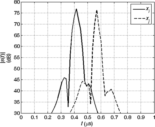
Figure 12. Absolute value of the echoes from the joints at coordinates xi and xj: la = 2 m, rap = 3%.
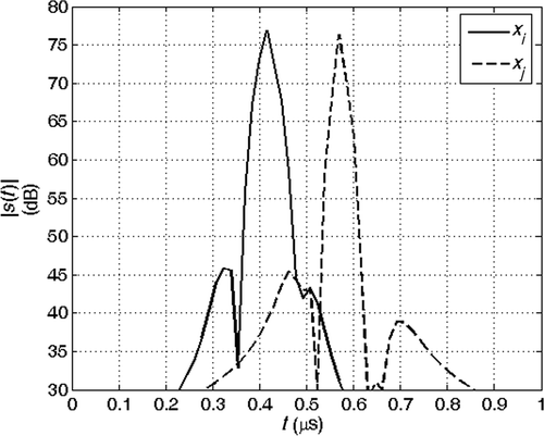
Figure 17. Mean value of the inverted anomaly length versus SNR. Exact solution: la = 2 m and rap = 3%.
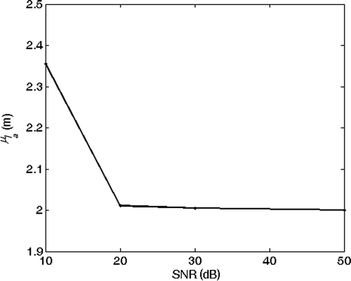
Figure 19. Mean value of the inverted percentage radius reduction versus SNR. Exact solution: la = 2 m and rap = 3%.
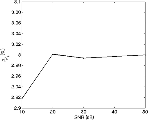
Figure 20. SD of the inverted percentage radius reduction versus SNR. Exact solution: la = 2 m and rap = 3%.
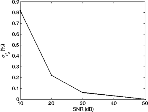
Table 1. Inverted parameters–synthetic data: regular (a) and deformed (b) elements.
5.2. Real data
We have acquired a real data set in controlled conditions (known anomaly parameters), in order to validate the inversion algorithm. The hollow metal cylindrical structure is composed of elements of (known) length l ≅12 m, welded together. The section located between the coordinate xi ≅ 96 m and xj ≅ 108 m has a radial reduction for a portion of its total length ls ≅ 12 m. The deformed element is inserted into the section by the means of two screwed flanges at the distances xF1 ≅ 99 m and xF2 ≅ 102 m (). We report two cases: (a) the absence of anomaly and (b) the circular anomaly of radial reduction rap ≅ 5% and deformation length la ≅ 3 m.
The acquisition system is a quasi-monostatic pulse radar Citation17–20 equipped with an antenna operating at vertical polarization employed both as transmitter and receiver. Its response is assumed to be constant in the frequency range of interest. Coherent transmission and reception are performed. The input signal is the same one introduced in the synthetic data example (Figures ). In order to increase the SNR, the system returns the mean of a given number (≈10,000) of acquisitions, with fixed geometry and input signal.
Real data are affected by different sources of noise ( and ):
| 1. | random noise (SNR ≅ 30 dB in the analysed signals); | ||||
| 2. | RF spurious noise signals; | ||||
| 3. | leakage at low frequency and | ||||
| 4. | spurious echoes due to the flanges. | ||||
Figure 22. Real data for a regular section. The arrows indicate the starting time of the echoes from the joints.
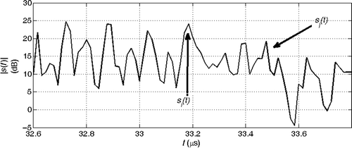
Figure 23. Real data for a deformed section. The arrows indicate the starting time of the echoes from the joints.
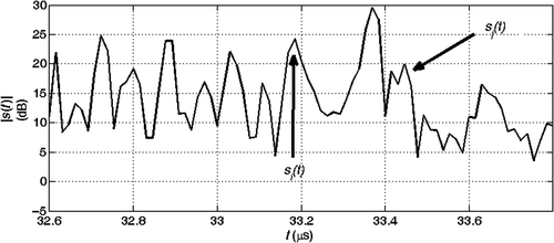
We successfully reduce the effect of the noise by filtering, except for the spurious echoes due to the flanges. These artificial discontinuities (i.e. not present in a structure made of constant length elements) generate backscattered signals that interfere with the echoes from the joints delimiting the section during the analysis.
We propose two approaches in order to lower the effect of the flange reflection noise:
| 1. | Estimate the echoes of the flanges and then remove them from the recorded data: this solution is complicated by the fact that it is necessary to model the flanges and | ||||
| 2. | Evaluate the phase constant from the reflections of one joint long way before the anomaly and the other past the anomaly, where the flange interference noise is strongly attenuated: this solution increases the condition number associated to the inverse problem. | ||||
We find a good compromise by applying both the previous approaches. First, we estimated and removed the echoes due to joints and flanges, thanks to an accurate knowledge of the position of the discontinuities along the structure. Then, since the previous procedure does not completely remove the interfering echoes, we doubled the section length, by considering the reflections from the joints at xi ≅ 84 m and xj ≅ 108 m (ls ≅ 24 m).
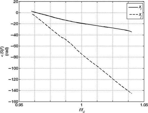
and are the extracted echoes (absolute value). and show the phase of the spectrum of the echoes during the analysis and and are the phase of their ratio, which is proportional to βobs(f). The estimated anomaly parameters are reported in . The accuracy of the result is interesting for many applications.
Figure 24. Absolute value of the echoes from the joints at coordinates xi = 84 m and xj = 108 m: real data with regular section.
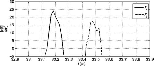
Figure 25. Absolute value of the echoes from the joints at coordinates xi = 84 m and xj = 108 m: real data with deformed section.
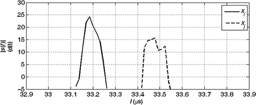
Figure 28. Phase of the spectra ratio of the joints echoes at xi = 84 m and xj = 108 m: real data with regular section.
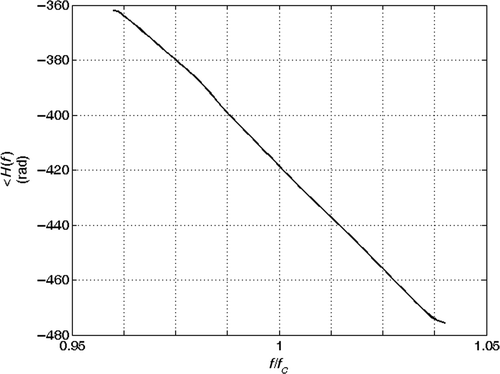
Figure 29. Phase of the spectra ratio of the joints echoes at xi = 84 m and xj = 108 m: real data with deformed section.
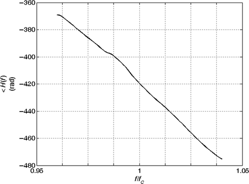
Table 2. Inverted parameters–real data: regular (a) and deformed (b) elements.
6. Conclusions
We have presented an indirect technique which is able to detect and to quantify circular anomaly parameters inside a hollow metal cylindrical structure. It operates remotely by sending an electromagnetic signal from an open end of the structure and by recording and processing the backscattered signal. The maximum distance of detection is limited by the noise and by the attenuation of the transmission line.
The detection procedure analyses the echoes due to the localized discontinuities along the structure (like the joints, whose position is known), and obtains the geometrical parameters of the crossed sections, by inverting the relation between the signal and the hollow element parameters. The condition number of the inverse problem increases with the distance between the joints, whose backscattered signals are used in the processing.
The precision of the inversion strongly depends on the correct extraction of the reflections from the junctions: this implies an appropriate SNR and a good description of the interference effects. Interfering events could be treated with a ‘section stripping’ approach: the section parameters are estimated and removed in sequence one at a time.
We have tested the procedure on synthetic and real cases, showing that the estimation accuracy can be interesting for many applications.
The inversion procedure presented here is quite general because it is based on the phase difference measurements and it is, therefore, independent from the transmitted signal and from the antennas. Future developments are the inclusion of higher order propagation modes and the extension of the operative frequency range.
Acknowledgements
We thank Adriano Calzavara (Saipem SpA), Antonio Passerini (Saipem SpA) and Roberto Visentin (Saipem Energy Services SpA Div SONSUB) for providing the real data set, for the permission to show these results and for the valuable discussions.
References
- Association of Oil Pipelines (AOPL) and American Petroleum Institute (API), Pipeline Integrity in Detail 2002. Available at http://www.aopl.org.
- Gazis, DC, 1959. Three-dimensional investigation of the propagation of waves in hollow circular cylinder, J. Acoustic Soc. Am. 31 (1959), pp. 568–573.
- Shin, HJ, and Rose, JL, 1998. Guided wave tuning principles for defect detection in tubing, J. Nondestr Eval. 17 (1998), pp. 27–36.
- Lowe, MJS, Alleyne, DN, and Cawley, P, 1998. Defect detection in pipes using guided waves, Ultrasonic 36 (1998), pp. 147–154.
- Cawley, P, Lowe, MJS, Alleyne, DN, Pavlakovic, B, and Wilcox, P, 2003. Practical long range guided wave testing: Applications to pipes and rail, Mater. Eval. 61 (2003), pp. 66–74.
- Barshinger, J, Rose, JL, and Avioli, MJ, 2002. Guided wave resonance tuning for pipe inspection, J. Pressure Vessel Technol. 124 (2002), pp. 303–310.
- Ferrante, M, and Brunone, B, 2003. Pipe system diagnosis and leak detection by unsteady-state tests. 1: Harmonic analysis, Adv. Water Resour. 26 (2003), pp. 95–105.
- Mallett, R, Mudge, PJ, Gan, T-H, and Balachandran, W, 2007. Analysis of cross-correlation and wavelet de-noising for the reduction of the effects of dispersion in long-range ultrasonic testing, Insight 49 (2007), pp. 350–355.
- Satyarnarayan, L, Chandrasekaran, J, and Maxfield, B, 2008. Circumferential higher order guided waves modes for the detection and sizing of cracks and pinholes in pipe support regions, NDT and E Int. 41 (2008), pp. 32–43.
- P.J. Mudge and Phil Catton, Quantification of defect size from long range guided wave ultrasonic tests on pipes. Review of progress in quantitative nondestructive evaluation: AIP Conference Golden, CO, USA. Proceedings of 34th annual review of progress in quantitative nondestructive evaluation, Vol. 975, 2007, pp. 147–154..
- Rizzo, P, Bartoli, I, Marzani, A, and di Scalea, FL, 2005. Defect classification in pipes by neural networks using multiple guided ultrasonic wave features extracted after wavelet processing, J. Pressure Vessel Technol. 127 (2005), pp. 294–303.
- Pan, T-W, Hsue, C-W, and Huang, J-F, 2002. Time-domain reflectometry using arbitrary incident waveforms, IEEE Trans. MTT 50 (2002), pp. 2558–2563.
- Ramo, S, Whinnery, JR, and Van Duzer, T, 1994. Fields and Waves in Communication Electronics. NY: John Wiley & Sons; 1994.
- Rovetta, D, Bosisio, AV, and Drufuca, G, 2006. Propagation constant of HE11 mode near the cutoff frequency in a circular waveguide, IEEE Microw Wireless Compon Lett. 16 (2006), pp. 314–316.
- Tarantola, A, 1987. Inverse Problem Theory. Amsterdam: Elsevier; 1987.
- Taner, MT, Koehler, F, and Sheriff, RE, 1979. Complex seismic trace analysis, Geophysics 44 (1979), pp. 1041–1063.
- Siebert, WM, 1956. A radar detection philosophy, IEEE Trans. Inf Theory 2 (1956), pp. 204–221.
- Skolnik, MI, 1962. Introduction to Radar Systems. New York: McGraw-Hill; 1962.
- Skolnik, MI, 1990. Radar Handbook. New York: McGraw-Hill; 1990.
- Curlander, JC, and McDonough, RN, 1991. Synthetic Aperture Radar, Systems and Signal Processing. New York: John Wiley and Sons; 1991.


