Abstract
In this article, we propose a simple method for detecting an inclusion Ω2 embedded in a host electrostatic medium Ω1 from a single Cauchy pair of voltage and current flux measurements on the exterior boundary of Ω1. A nonlinear constrained minimization regularized method of fundamental solutions is developed for the numerical solution of this inverse problem. The stability of the numerical scheme is investigated by inverting measurements contaminated by random noise.
AMS Subject Classifications::
1. Introduction
It is well-known (see, e.g. Citation1), that electrical impedance tomography (EIT) is a non-intrusive technique in which an image of conductivity of the interior of an object is inferred from the surface measurements of electrical quantities. Mathematically, if u denotes the electric potential and n the outward unit normal, given measurements of a pair of (u, ∂nu) = (voltage, current flux) on the accessible outer boundary ∂Ω1, we search for an unknown inclusion (anomaly) Ω2 with conductivity k ≠ 1, representing, say, a tumour, within the conducting host medium Ω1. Some uniqueness results exist for determining the inclusion Ω2 in this case, this is a polyhedron or a ball from known single Cauchy data pair measurements Citation2,Citation3. The problem is still, however, difficult to solve since it is non-linear, ill-posed (unstable) and computationally intensive Citation4–8. Prior to this study, this transmission problem was investigated using the boundary element method (BEM) and its variants in, for example, Citation9–12.
Very recently, a new inverse problem algorithm, which uses the method of fundamental solutions (MFS) iteratively for the determination of a perfectly conducting (k = 0) or a perfectly insulated (k = ∞) inclusion, has been proposed in Citation13 and Citation14, respectively. The goal of this study is to extend this approach to the more realistic (and difficult) case when 0 < k ≠ 1 < ∞.
This article is organized as follows. The mathematical formulation of the problem is given in Section 2. The MFS and the proposed nonlinear iterative regularization algorithm are described in Section 3. Numerical results are presented in Section 4 and, finally, in Section 5 some conclusions and suggestions for future applications are given.
2. Mathematical formulation
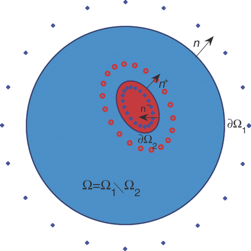
The inverse conductivity problem can be formulated mathematically in the following way. Let Ω1 be a bounded domain in ℝd, d ≥ 2, with a Lipschitz boundary and Ω2 a subdomain compactly contained in Ω1, such that Ω ≔ Ω1\Ω2 is connected (). The refraction (transmission, conjugate) problem for the electrical potential u is given by
(1)
subject to the Dirichlet boundary condition
(2)
and to refraction conditions related to the continuity of the voltage u and the current flux densities ∂u/∂n− and k ∂u/∂n+ across the interface ∂Ω2. Here n− and n+ are the outward unit normals to the boundaries ∂Ω\∂Ω1 and ∂Ω2, respectively. In (2.1a), 𝒳Ω2 denotes the characteristic function of the domain Ω2 and f ∈ L2(∂Ω1) is a given (voltage) function. It is well-known Citation15, p.197] that the direct problem of finding u ∈ H1(Ω1) satisfying (2.1a) and (2.1b), when k and Ω2 are known, has a unique solution. Assuming that k is known, the inverse conductivity problem requires finding Ω2 from the knowledge of the Dirichlet-to-Neumann map for finitely many data f ∈ L2(∂Ω1).
The refraction model under investigation given by Equations (2.1a) and (2.1b), and the corresponding transmission conditions on the interface ∂Ω2 can be recast in a more convenient form, by defining u = u1 in Ω and u = u2 in Ω2, where u1 and u2 satisfy
(3)
(4)
(5)
and
(6)
If we now assume that Ω1 and Ω2 are simply connected and have a C2 boundary, then
and u2 ∈ H2(Ω2), see Citation15, p.198].
In the inverse problem, given a non-constant voltage Dirichlet input data f ∈ L2(∂Ω1), we measure the corresponding Neumann current flux
(7)
in order to determine the solution pair (u, Ω2).
When k =constant, the geometrical inverse problem given by Equations (2.2a–2.2e) is well-suited for the application of the BEM Citation11,Citation12, or the MFS, as will be described in Section 3.
3. The method of fundamental solutions
The MFS may be viewed as a meshless BEM in which the governing potential field is approximated by a linear combination of the fundamental solutions of the operator of the governing equation under consideration. These fundamental solutions are given in terms of singularities which are positioned outside the domain of the problem. In contrast to the BEM, the MFS provides accurate approximations directly at points arbitrarily close to the boundary. Moreover, since no integration of shape functions over boundary elements is involved, it is considerably easier to implement than the BEM Citation16,Citation17. The MFS has been successfully used in the past for the solution of free boundary problems and composite material problems, see Citation18 and Citation19, respectively.
In the MFS we seek approximations and
to the solutions u1 and u2, respectively, of Equations (2.2a–2.2e) with k =constant, as linear combinations of fundamental solutions in the form Citation20
(8)
(9)
where G is a fundamental solution of the Laplace equation, given by
(10)
The singularities (sources)
are located outside
, i.e. in
, while the singularities
are located outside
. In particular,
and
are placed on (moving) pseudo-boundaries
and
similar to ∂Ω2, at a distance δ > 0 inwards and outwards, respectively. The remaining singularities
are placed on a (fixed) pseudo-boundary
similar to ∂Ω1, as depicted in . In the MFS, taking the pseudo-boundary similar to the boundary yields, in general, improved results as has been demonstrated in a recent study by Gorzelańczyk and Kołodziej Citation21. In (3.1) and (3.2), the singularities
are fixed, whereas the singularities
and
move with ∂Ω2 as will be described in the iterative process presented in the sequel.
For simplicity, we take d = 2, and without loss of generality, we shall assume that the (known) fixed exterior boundary ∂Ω1 is a circle of radius 1; otherwise, we first conformally map the exterior of Ω1 onto the exterior of the unit circle. As a result, the outer boundary collocation and source points are chosen as
(11)
(12)
respectively, where
and
, and R > 1 is fixed.
We further assume that the unknown boundary ∂Ω2 is a smooth, star-like curve with respect to the origin such that in polar coordinates its equation can be written as
(13)
where r is a smooth 2π-periodic function. (A similar but more tedious analysis can be performed in three dimensions through the use of spherical coordinates.)
Using (3.6), the flux continuity condition in (2.2d) can be rewritten as
(14)
which, since
(15)
becomes
(16)
The discretized form of (3.6) for ∂Ω2 becomes
(17)
and we choose the boundary collocation and inner and outer source points as
(18)
and
(19)
The way the parameter η ∈ (0, 1) is chosen is discussed at the end of this section.
The coefficients in (3.1) and (3.2) and the radii
in (3.10) can be determined by imposing the boundary conditions (2.2b), (2.2d) and (2.2e) in a least-squares sense. This leads to the minimization of the functional S : ℝ2N × ℝN × (0, 1)N → ℝ+ defined by
(20)
where λ1, λ2 ≥ 0 are regularization parameters to be prescribed.
Remarks
| i. | Equation (3.13) represents the discretized version of the continuous L2-norms. | ||||
| ii. | The current flux data (2.2e) comes from practical measurements which are inherently contaminated with noisy errors and we, therefore, replace g by gϵ such that
| ||||
| iii. | In (3.13), the outward normal vectors are defined as follows:
| ||||
| iv. | Since Equation (3.13) imposes 2M + 2N equations with 4N unknowns, in general, we shall take M ≥ N. Also, the constraints | ||||
| v. | Since the inverse problem is ill-posed, in (3.13) the regularization terms λ1 {|c1|2 + |c2|2} and/or λ2|r|2 are added in order to achieve the stability of the numerical solution for u1, u2 and Ω2. The coefficients c1 and c2 are also penalized in the regularization since it is well-known that the MFS is rather ill-conditioned, especially when the input data contains noisy errors Citation23. | ||||
The MFS algorithm described in this section for solving the inverse problem (2.2) for isotropic piecewise homogeneous conductors can be extended to anisotropic conductors. In such a case, we replace the fundamental solutions (3.3) by
(26)
where K is the symmetric positive definite anisotropy tensor entering the Laplace–Beltrami equation
(27)
|K−1| is the determinant of the inverse matrix K−1 and
.
4. Numerical examples
4.1. Example 1
We first consider an example for which an exact solution is known and given by, Citation25,
(28)
(29)
(30)
where r0 ∈ (0, 1), k ≠ 1 and Ω1 = B(0, 1).
This exact solution satisfies problem (2.2), with
(31)
and
(32)
In our numerical experiments we consider the case r0 = 0.5. We also take k = 10. In the minimization of (3.13), the initial location of ∂Ω2 was taken to be a circle of radius r(0) = 0.3 and c1 = c2 = 0.
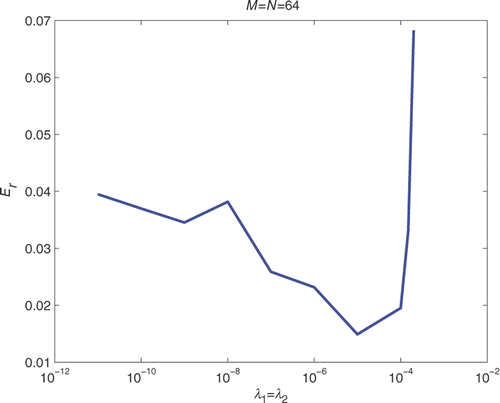
In , we present the recovered contours obtained with no regularization for noise levels of p = 0, 1%, 3%, 5%, respectively, for nfev = 1000. The parameter η in (3.12) was chosen to be 0.6, and for each noise level we took N = M = 16, 32, 48 and 64. As expected, as the level of noise increases, the recovered contours start to deteriorate slightly. However, the numerical solutions presented in are still reasonably accurate and stable, even when no regularization is imposed in (3.13). In this case, the stability of the numerical solution is achieved by limiting the number of function evaluations to nfev=1000. Increasing the value of nfev to 5000, 10,000 and 15,000 tends to produce a slightly more unstable solution, as can be observed from . In this case, the stability can be restored if one employs regularization, as shown in . From this figure, it can be seen that for N = M = 64, p = 5% and nfev =15,000, the optimal value of the regularization parameters λ1 = λ2 in (3.13) appears to be of O(10−5).
Figure 2. Results with no regularization λ1 = λ2 = 0, nfev=1000, M = N ∈ {16, 32, 48, 64} and p ∈ {0, 1, 3, 5}%, for Example 1.
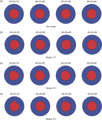
Figure 3. Results with no regularization λ1 = λ2 = 0, N = M = 64, p = 5% for various numbers of function evaluations nfev ∈ {1, 5, 10, 15} × 103, for Example 1.

Figure 4. Results with N = M = 64, p = 5%, nfev=15,000 and various regularization parameters λ1 = λ2 ∈ {0, 10−8, 10−5, 10−3}, for Example 1.

In order to assess the accuracy of the numerical solution obtained in , we calculated the maximum error in the final positions of the points defining the cavity, namely
(33)
Clearly, the smaller the Er, the better the solution. In we present the plot of Er versus the regularization parameters λ1 = λ2, from which it appears that the best results are indeed obtained for λ1 = λ2 = O(10−5).
Although not illustrated, it has been observed that smaller inclusions with radii up to r0 = 0.1 = 10% of the characteristic size of the enclosing body Ω1 were also detected with a reasonable accuracy. Obviously, smaller inclusions (tumours) are more difficult to detect both accurately and stably Citation5. On the other hand, in the extreme case when there is no inclusion, i.e. k = 1, the iterative algorithm terminates immediately by returning a vanishingly small unrealistic inclusion.
4.2. Example 2
In this example, we consider the more complicated bean-shaped inclusion ∂Ω2 given by the radial parameterization
(34)
This example, which was also considered in Citation26, is significantly more difficult than Example 1 because of the presence of a sharp cusp-like portion mimicking a re-entrant corner.
The Dirichlet voltage data (2.2b) on ∂Ω1 is taken as in Citation27
(35)
We also take k = 6. Since in this case no analytical solution to problem (2.2) is available, the Neumann current flux data (2.2e) is simulated numerically by solving the well-posed direct problem (2.2a–2.2d) and (4.8), when ∂Ω2 is given by (4.7), using the MFS with M = N = 96. In order to avoid committing an inverse crime, the inverse solver based on the minimization of (3.13) is applied using a different number M = N = 64. Furthermore, noise is added as in (3.15). The parameter η in (3.12) was chosen to be 0.2. The initial guess for ∂Ω2 was taken to be a circle of radius r(0) = 0.5 and c1 = c2 = 0.
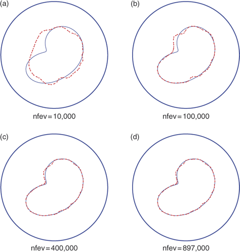
In , we present the reconstructed and the exact shapes obtained with no noise and no regularization for various numbers of nfev. The results obtained for a sufficiently large nfev are in very good agreement with the exact shape. Note that maxfev was set to 1,000,000 but lmdif terminated for nfev=897,000 (, indicating that convergence was reached before the number of function evaluations reached maxfev.
Figure 6. Results with no noise p = 0, no regularization λ1 = λ2 = 0 and various numbers of function evaluations, for Example 2.
In Figures , we present the reconstructed and the exact shapes obtained with noises p ∈ {1, 3, 5}%, respectively, and no regularization for various numbers of nfev. The results indicate that visible instabilities start to manifest if no regularization is imposed and the amount of noise p and/or the number of function evaluations nfev increases. Note that maxfev was set equal to 1,000,000, but lmdif terminated for nfev=620,000 (, again indicating that the convergence was reached before the number of function evaluations reached maxfev.
Figure 7. Results with noise p = 1%, no regularization λ1 = λ2 = 0 and various numbers of function evaluations, for Example 2.
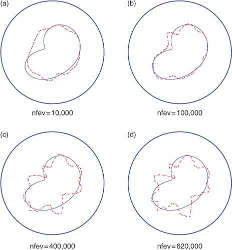
Figure 8. Results with noise p = 3%, no regularization λ1 = λ2 = 0 and various numbers of function evaluations, for Example 2.
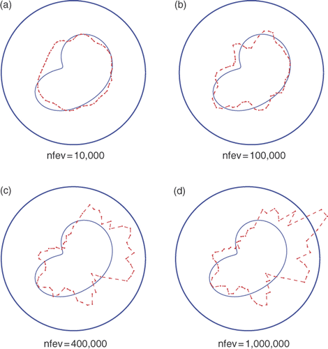
Figure 9. Results with noise p = 5%, no regularization λ1 = λ2 = 0 and various numbers of function evaluations, for Example 2.
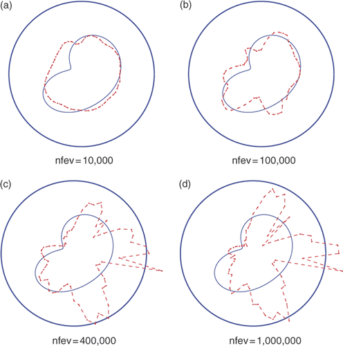
In order to overcome the instability of the numerically reconstructed shapes, regularization is imposed in the functional (3.13). The numerical results with regularization for p ∈ {1, 3, 5}% are presented in Figures , respectively. Each of the figures presents numerical results for the reconstructed shapes when λ2 = 0 and λ1 ∈ {0, 10−6, 10−5, 5 × 10⁻⁵, 10−4, 10−3} and the maximum number of function evaluations is prescribed as maxfev=1,000,000. It is noteworthy that, unlike the results of Figures , in Figures the presence of the regularization λ1 > 0 can reduce the number of function evaluations nfev, i.e. convergence is reached for fewer function evaluations than the prescribed number maxfev=1,000,000.
Figure 10. Results with noise p = 1%, prescribed maxfev = 106 and various regularization parameters λ1 ∈ {0, 10−6, 10−5, 5 × 10⁻⁵, 10−4, 10−3}, λ2 = 0, for Example 2.
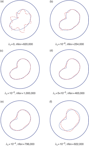
Figure 11. Results with noise p = 3%, prescribed maxfev = 106 and various regularization parameters λ1 ∈ {0, 10−6, 10−5, 5 × 10⁻⁵, 10−4, 10−3}, λ2 = 0, for Example 2.
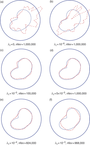
Figure 12. Results with noise p = 5%, prescribed maxfev = 106 and various regularization parameters λ1 ∈ {0, 10−6, 10−5, 5 × 10⁻⁵, 10−4, 10−3}, λ2 = 0, for Example 2.
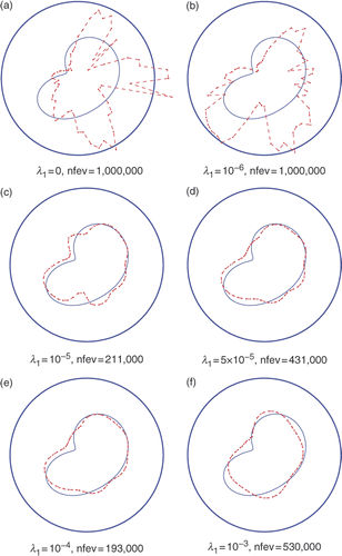
From Figures it can be observed that the best results are obtained for λ1 between 10−5 and 10−4.
5. Conclusions
A novel numerical method based on a regularized iterative MFS has been developed for the approximate solution of the inverse conductivity problem. The MFS was employed because, while it shares most of the advantages of the BEM for such geometrical inverse problems, it is considerably easier to implement and does not involve potentially troublesome integrations. In the inverse analysis a fast direct solver is often needed with iterative minimization procedures and, especially in higher dimensions, the MFS, being meshless, is much faster than other domain and boundary discretization methods. There is, however, a compensating cost to be paid for the ease of implementation of the MFS, for example, the method is rather ill-conditioned, especially when the input data contains noisy errors Citation23. The MFS was applied to two such problems with known and unknown analytical solutions, and the effects of the number of function evaluations and regularization was studied for noisy data up to 5%. The numerical results indicate that accurate reconstructions with reasonable stability against noisy data can be produced with the proposed method. Further numerical experiments indicated that for a noisy level above 10% the reconstructions began to deteriorate. While in this numerical study the regularization parameters λ1 and λ2 were chosen by trial and error, more rigorous criteria such as the discrepancy principle will be investigated in a future study. It is also possible that stopping the iterative minimization process at an appropriate threshold (depending on the amount of noise) plays the role of regularization. Future work will also involve extending the numerical implementation of the MFS to the retrieval of multiple inclusions and to three-dimensional problems.
Acknowledgements
The authors would like to thank the University of Cyprus for supporting this research. The comments of the referees and the associate editor are also gratefully acknowledged.
References
- Borcea, L, 2002. Electrical impedance tomography, Inverse Probl. 18 (2002), pp. R99–R136.
- Isakov, V, 2006. Inverse Problems for Partial Differential Equations, . Berlin: Springer-Verlag; 2006.
- Kang, H, and Seo, JK, 2000. "Recent progress in the inverse conductivity problem with single measurement". In: Nakamura, G, Saitoh, S, Seo, JK, and Yamamoto, M, eds. Inverse Problems and Related Topics. New York: Chapman & Hall/CRC; 2000. pp. 69–80.
- Ammari, H, 2008. An Introduction to Mathematics of Emerging Biomedical Imaging, Mathématiques & Applications. Vol. 62. Berlin: Springer-Verlag; 2008.
- Ammari, H, and Kang, H, 2004. Reconstruction of Small Inhomogeneities from Boundary Measurements, Lecture Notes in Mathematics. Vol. 1846. Berlin: Springer-Verlag; 2004.
- Ammari, H, and Kang, H, 2007. Polarization and Moment Tensors: With Applications to Inverse Problems and Effective Medium Theory, Applied Mathematical Sciences. Vol. 162. New York: Springer-Verlag; 2007.
- Ammari, H, Kwon, O, Seo, JK, and Woo, EJ, 2004. Anomaly detection in T-scans trans-admittance imaging system, SIAM J. Appl. Math. 65 (2004), pp. 252–266.
- Kwon, K, Seo, JK, and Yoon, JR, 2002. A real-time algorithm for the location search of discontinuous conductives with one measurement, Comm. Pure Appl. Math. 55 (2002), pp. 1–29.
- Kagawa, YY, Xu, W, Zhao, Y, Horikane, T, Wakatsuki, N, and Totsuji, H, 2006. 3D direct inversion algorithm for electrical impedance underground anomaly detection with dual reciprocity boundary element modeling, Inverse Probl. Sci. Eng. 14 (2006), pp. 639–650.
- Kwon, K, 2008. Integral representations in electrical impedance tomography using boundary integral operators, J. Korean Math. Soc. 45 (2008), pp. 97–119.
- Murai, T, and Kagawa, Y, 1986. Boundary element iterative techniques for determining the interface boundary between two Laplace domains–A basic study of impedance plethysmography as an inverse problem, Inter. J. Numer. Methods Eng. 23 (1986), pp. 35–47.
- de Munck, JC, Faes, TJC, and Heethaar, RM, 2000. The boundary element method in the forward and inverse problems of electrical impedance tomography, IEEE Trans. Biomed. Eng. 47 (2000), pp. 792–800.
- Borman, D, Ingham, DB, Johansson, BT, and Lesnic, D, 2009. The method of fundamental solutions for detection of cavities in EIT, J. Integral Eqns Appl. 21 (2009), pp. 381–404.
- Karageorghis, A, and Lesnic, D, 2009. Detection of cavities using the method of fundamental solutions, Inverse Probl. Sci. Eng. 17 (2009), pp. 803–820.
- Ladyzenskaya, OA, 1985. The Boundary Value Problems of Mathematical Physics. Berlin: Springer-Verlag; 1985.
- Fairweather, G, and Karageorghis, A, 1998. The method of fundamental solutions for elliptic boundary value problems, Adv. Comput. Math. 9 (1998), pp. 69–95.
- Golberg, MA, and Chen, CS, 1999. "The method of fundamental solutions for potential, Helmholtz and diffusion problems". In: Golberg, MA, ed. Boundary Integral Methods: Numerical and Mathematical Aspects, Vol. 1 of Computational Engineering. Boston, MA: WIT Press; 1999. pp. 103–176.
- Karageorghis, A, 1992. The method of fundamental solutions for the solution of steady-state free boundary problems, J. Comput. Phys. 98 (1992), pp. 119–128.
- Berger, JR, and Karageorghis, A, 1999. The method of fundamental solutions for heat conduction in layered materials, Int. J. Numer. Meth. Eng. 45 (1999), pp. 1681–1694.
- Mathon, R, and Johnston, RL, 1977. The approximate solution of elliptic boundary-value problems by fundamental solutions, SIAM J. Numer. Anal. 14 (1977), pp. 638–650.
- Gorzelańczyk, P, and Kołodziej, JA, 2008. Some remarks concerning the shape of the source contour with application of the method of fundamental solutions to elastic torsion of prismatic rods, Eng. Anal. Boundary Elem. 32 (2008), pp. 64–75.
- Numerical Algorithms Group Library Mark 21, NAG(UK) Ltd, Wilkinson House, Jordan Hill Road, Oxford, UK (2007)..
- Chen, CS, Cho, HA, and Golberg, MA, 2006. Some comments on the ill-conditioning of the method of fundamental solutions, Eng. Anal. Boundary Elem. 30 (2006), pp. 405–410.
- Garbow, BS, Hillstrom, KE, and Moré, JJ, 1980. MINPACK Project. Argonne National Laboratory; 1980.
- Lesnic, D, 2001. A numerical investigation of the inverse potential conductivity problem in a circular inclusion, Inverse Probl. Eng. 9 (2001), pp. 1–17.
- Eckel, H, and Kress, R, 2007. Nonlinear integral equations for the inverse electrical impedance problem, Inverse Probl. 23 (2007), pp. 475–491.
- Ivanyshyn, O, and Kress, R, 2006. Nonlinear integral equations for solving inverse boundary value problems for inclusions and cracks, J. Integral Eqns. Appl. 18 (2006), pp. 13–38.
