Abstract
An inverse time-marching solution of Euler equations is performed in the meridional plane of a complete machine. The method predicts the flowfield and blade cambersurface geometry that correspond to a specified load distribution in the blade regions. The implicit approach is used to solve Euler equations with a specified mass flowrate at the outlet section. This boundary condition leads to typical turbine solutions of the inverse problem. The implicit upwind scheme is based on a time linearization of Osher's flux difference splitting operator. This operator employs a high-order Riemann solution that provides second-order space accuracy. For infinite-span turbine cascades working in the low-subsonic range, the new method has convergence times and residuals that are one order of magnitude lower than previous explicit methods. It keeps the same convergence properties up to the sonic outflow conditions, while explicit methods fail in the high-subsonic range. When endwalls are included in the computation to design finite-span cascades or complete turbine stages, the method still encounters some numerical instabilities that can be partly overcome using a sufficient mesh resolution in the spanwise direction.
1. Introduction
Despite the ever increasing computational resources that become available, full three-dimensional flow simulations are still far from being routinely used for the design and analysis of multistage axial flow turbomachinery. Throughflow tools remain essential in the aerodynamic design and optimization process, especially from an industrial point of view Citation1. Throughflows are based on the assumption of axisymmetric flow, and traditionally solve the radial equilibrium equations by means of streamline curvature or streamfunction methods (see e.g. Citation2). Over the past 15 years, several attempts have been made to use CFD-based methodologies for axisymmetric computations. The latest-generation models perform time-marching solutions of the more exhaustive sets of Euler Citation3–6 and Navier–Stokes Citation7,Citation8 equations in the meridional plane of a complete machine. In these models, the blades come down to hub-to-tip streamsurfaces and their effect on the flow is obtained by means of a suitable blade force distribution. From the industrial point of view, inverse approaches Citation4,Citation6 are especially appealing, because they allow the designer to define the detailed geometry of the blade cambersurfaces from the axisymmetric stage of the design process. Nowadays, three-dimensional inverse solvers are dedicated to this task, which take the outcome of the traditional throughflow computations as input data.
The present work uses the Euler model that was addressed by Bena et al. Citation6 for axial flow compressor design for turbine design. In their inverse formulation, the blade load distribution, i.e. the tangential component of the inviscid blade force field, is specified as the main design parameter. The method predicts the axisymmetric flowfield and draws the corresponding hub-to-tip streamsurface geometry from the surface-flow slip equation. As pointed out in reference Citation9, specifying the load distribution on the blade regions of the meridional flowpath is somewhat arbitrary. The authors agree with this remark, but believe that an inverse optimization process, like the one addressed in reference Citation10, can be effectively used to set up this design parameter.
The extension of the same approach to the higher blade loads and flow deflections that are typical of aeronautical turbines is not straightforward. Addressing the one-dimensional formulation of the inverse problem, Zannetti and Pandolfi Citation11 showed that when Euler equations are solved with conventional boundary conditions, i.e. total quantities and flow angle at the inlet section and static pressure at the outlet section, the time-marching methodology can only lead to low-deflection cascades. In order to make the high-deflection solutions also stable, the same authors investigated the introduction of a discontinuity surface at the outlet section. This discontinuity forced the blade to produce the desired outflow angle. In the present work, the authors would first like to show that one way of numerically obtaining any theoretical solution of the one-dimensional inverse problem, at least in principle, is to perform the numerical computation for a given mass flowrate. This quantity can be either specified at the inlet section, instead of one of the total quantities, or at the outlet section, instead of the static pressure. The first option allows the method to treat transonic flows, which is an important advantage of time-marching models Citation3–6 over the traditional throughflow tools. However, since streamline curvature and streamfunction methodologies also need total quantities and mass flowrate to be known, the authors here prefer to focus on the second option. Specifying the mass flowrate at the outlet section has strong numerical implications. The new boundary condition becomes more and more reflective as the outlet Mach number increases Citation12 to the detriment of the convergence properties of the numerical methods used so far. When coupled to it, the upwind explicit schemes of references Citation6,Citation11,Citation13 still succeed only for turbine solutions with a very moderate load and deflection. One method that can be used to face the drawback, at least in a measure, is to specify the mass flowrate through a either totally or partly non-reflective formulation. Reference Citation12 addressed a set of totally non-reflective boundary conditions based on the use of the Riemann invariants and an optimization process. On the other hand, partly non-reflective boundary conditions need a quite tiresome tuning process Citation14, especially in two-dimensional computations. The limits of the partly non-reflective approach will, however, be shown in the present work.
The authors here prefer to trust the inherent numerical properties of an implicit upwind time-marching scheme. Details of the implicit discretization of the Euler equations and surface–flow slip equation are given in Section 3. Section 2 revises the proposed inverse formulation in both the axisymmetric and one-dimensional cases. It also formalizes the concepts of low-, high- and limit-deflection cascades. Numerical solutions of the one-dimensional and axisymmetric inverse problem for turbine configurations are presented and discussed in Section 4. The concluding remarks are given in Section 5.
2. The axisymmetric model and the inverse problem
The axisymmetric model Citation6 for axial flow turbomachinery shares the same basic idea as traditional throughflow models, where the hub-to-tip or S2 streamsurfaces come down to a single mean surface (). In the blade regions of the meridional flowpath, if deviation effects are neglected, this mean surface can be thought of as the cambersurface of the blade. In the axisymmetric Euler equations, the main effects of the real blade on the flow are modelled by means of a blade-to-blade blockage term and a blade force term, which can be further split into two contributions. The inviscid contribution turns the flow through the blade region and acts normal to the mean surface, whereas the viscous contribution is meant to model the profile loss effects and acts tangential to it.
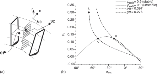
Figure 1. (a) Blade-to-blade S1 and hub-to-tip S2 streamsurfaces and (b) load curves for ,
and αinl = 20°.
The model is described by a set of equations written in cylindrical coordinates for an inertial reference frame. In the rest of the article, each quantity is normalized to conventional reference values. The adopted notation is listed in Appendix A.
| • | The surface–flow slip equation
| ||||
| • | Euler equations
| ||||
| • | The inviscid blade force equation
| ||||
2.1. The linear cascade problem
Apart from the complete axisymmetric formulation of the inverse problem, a more simple, one-dimensional formulation exists for infinite-span cascades. According to the throughflow approximation, the camberlines of such cascades coincide with streamlines in the tangential plane xz. The one-dimensional formulation of the inverse problem is used to design that particular cascade providing a specified load distribution along the axial chord. Its equations can be derived from Equations (1) to (3), by simply writing them in Cartesian coordinates and setting ∂/∂y and v to zero. For a stator cascade one obtains the form
(4)
where
The metal blockage factor is now defined as 1 − σxδz(x)/(xte − xle).
Reference Citation11 addressed a theoretical solution of steady equations (4) in the absence of viscous blade force and blockage terms. However, this solution could be easily generalized to include blockage effects. The same reference showed that numerical time-marching methods can re-obtain an inverse solution only when it obeys the stability condition
(5)
where
is the blade load. The curves Fi(αout) always have decreasing branches, but their extension is related to the specified boundary conditions. For a subsonic flow, there must be three conditions at the inlet section and a single one at the outlet section. The three load curves displayed in share the same inlet conditions
,
and αinl = 20°, but were drawn by setting three different outlet conditions. The curve passing through points A and B refers to the condition pexh = 0.9, the one passing through points A and L refers to the condition ϱu = 0.276 and finally the second curve passing through point B refers to the condition ϱu = 0.397. In view of stability condition (5), there is an essential difference between the first curve and the other two. The constant exhaust pressure load curves have three zeros. These correspond to the trivial solutions αout = αinl, where the mass flowrate is maximum, and αout = ±90° where the flowrate vanishes ( only shows the zero-load solution at αout = −90°). Therefore, when moving for instance from αout = αinl towards αout = −90°, the flowrate monotonically decreases, whereas the blade load first joins a maximum value, over which no physical solutions of the problem exist, then drops to zero. On the other hand, the constant flowrate curves do not stretch over the full range −90° < αout < 90°, but only over the interval −αlim < αout < αlim, where αlim is the limit angle that the flow takes in sonic conditions:
The limit blade load is defined as the load value that turns a flow with specified total quantities and mass flowrate from αinl to
. The point L in represents the limit solution for αinl = 20°,
,
and ϱu = 0.276. The constant flowrate load curves keep only one zero, which is still placed at αout = αinl. When moving from this point to the left, the outlet static pressure drops to the critical value, whereas the blade load monotonically increases up to the limit.
In view of stability condition (5), time-marching methods can re-obtain cascade B by specifying either pexh = 0.9 or ϱu = 0.397 at the outlet section. Conversely, in order to re-obtain cascade A, and even more so cascade L, the mass flowrate has to be specified. Cascades B and A share the same blade load, but the former produces it through a higher flowrate and lower deflection, whereas the latter produces it through a lower flowrate and higher deflection. The low-deflection cascades are typical of compressor blade rows. Aeronautical turbines usually work in the high-deflection region, with load levels closer and closer to the limit levels. It is clear from and the previous discussion that, working with a specified mass flowrate, an increase in flow deflection involves an increase in Mach number. Since this quantity is in turn related to the reflectiveness of the outlet condition, a robust numerical method is needed to solve Euler equations with strongly reflective boundary conditions.
3. The implicit upwind scheme
The proposed scheme uses a finite-volume space discretization of the meridional flowpath, with four-sided cells. The implicit time discretization is based on a Newton linearization of the numerical flux vectors Citation16. When it is applied to conservation law (2) for the ij-th volume, the linearization leads to the form
(6)
where
(7)
The space-variable time step Δtij in the expression of the coefficient [Cij] is adopted to increase the convergence speed of the scheme to the steady solution Citation17.
3.1. First-order space-accurate scheme
The right-hand side of scheme (6) is the same as the explicit scheme of reference Citation6. In order to compute, for instance, the numerical flux function {ℱi+1/2,j} = Φ({Wij}, {Wi+1,j}), the scheme uses the flux difference splitting technique by Osher Citation18. Osher's main idea is to break up the flux into a space-centred contribution plus an upwind correction, and to write this as
(8)
where [Λ−], [Λ+] and [V] are the negative eigenvalue, positive eigenvalue and right eigenvector matrices of [∂ℱ/∂W]. The integral in expression (8) is replaced by the sum of five flux jumps across as many waves propagating with a speed λ:
(9)
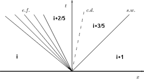
The fluxes {ℱi+k/5,j} and the wave speeds λk are obtained from an approximate first-order solution of a one-dimensional Riemann problem (i.e. the shock tube problem) in the direction normal to the interface i + 1/2, j. shows a typical wave pattern for a strictly one-dimensional flow, with the time axis placed at the interface between the volumes i and i + 1. The indices k = 0 and k = 5 refer to the initial states of the problem. The indices k = 2 and k = 3 refer to the two regions divided by a contact discontinuity, i.e. the wave λ3 = ui+2/5 = ui+3/5. Finally, k = 1 and k = 4 refer to the two sonic regions associated with the acoustic wave packages that go from λ1 = ui − ai to λ2 = ui+2/5 − ai+2/5 and from λ4 = ui+3/5 + ai+3/5 to λ5 = ui+1 + ai+1. No sonic flux is accounted for by the splitting (9) in the example of , where {ℱi+1/2} ≡ {ℱi+2/5}. When moving to two-dimensional flows, the initial states of the problem become
where {U} = (a u v w S)T is the primitive-variable vector and [ℛi+1/2,j] is the rotation matrix associated with the interface. This rotation expresses the meridional velocity vector through one component normal to the interface (i.e. u′) and the other parallel to the interface (i.e. v′).
In order to compute implicit coefficients (7), the same upwind principles can be applied to the Jacobian matrices of the numerical flux functions. The matrix [∂ℱi,j+1/2/∂Wij], for instance, is obtained by simply deriving expression (9). Here, the main drawback is to compute the matrix [∂ℱ/∂W] in the k-th Riemann region. The authors have overcome this problem by breaking up the matrix into four Jacobian matrices that involve elementary transformations. From the chain rule:
(10)
The first and the last matrices refer to simple variable changes in the same region. These two matrices are computed in Appendices B1 and B2 for the linear cascade problem, i.e. for v = 0. Extension to the general axisymmetric problem is straightforward. The second matrix refers to the Riemann problem solution, here expressed as a transformation between primitive variables in different regions. Its structure arises from the linear equations of the approximate Osher solver. The following equalities for k = 0, k = 1, k = 4 and k = 5 are trivial:
The other Jacobian matrices obtained from Osher's solver for k = 1 and k = 4, together with all those obtained for k = 2 and k = 3, are shown in Appendix B3 for the case of a linear cascade flow. The authors point out that, when solving the Riemann problem, the tangential velocity component w is assumed to remain constant along the u waves, together with the entropy. Indeed, λ = u is a two-multiplicity eigenvalue of the matrix [∂F/∂W] = [∂F/∂U][∂U/∂W], associated with the Riemann variables w and S. These concepts are extended to two-dimensional flows in the spirit of references Citation18,Citation19.
The other numerical flux vectors that appear on the right-hand side of scheme (6), as well as the other Jacobian matrices in implicit coefficients (7), are computed in a similar way to that described above.
3.2. Boundary conditions
The proposed scheme prescribes physical boundary conditions according to the theory of characteristics for hyperbolic systems of equations. In the spirit of reference Citation20, a partial Riemann problem is solved at the boundary interfaces. In this problem, one of the initial states disappears and is replaced by the same number of conditions as the incoming waves. For a subsonic axisymmetric flow, only one condition is needed along the outlet section of the flowpath and four conditions are needed along the inlet section. As previously explained, for the purposes of the present inverse formulation the former must be the mass flowrate ϱu, whereas the latter consist of two total quantities and the ramp and blade-to-blade flow angles. Finally, the slip condition u′ = 0 is prescribed at endwall interfaces.
When moving from the internal interfaces to the boundaries, only the second Jacobian matrix in the product (10) has to be modified, in order to account for the boundary conditions and the partial Riemann problem that is solved from them. For instance, along the inlet section i = 0, with k = 2–5, the Jacobian matrices will depend on {Binl,j} and
, where
is the boundary condition vector at the j-th inlet interface. Since the partial Riemann solution must be expressed in closed form to compute these Jacobian matrices, the flow state on the boundary is linearized with respect to the remaining initial state, whenever the prescribed conditions need it.
3.3. Second-order space-accurate scheme
Making the proposed scheme second-order space-accurate is straightforward. Instead of a constant flow solution over each volume, a linear solution is assumed in both grid directions. A high-order solution of the Riemann problem is, therefore, obtained at the volume interfaces. For the usual interface, i, j + 1/2, the initial states of the problem become
where {ΔiUij} and {ΔiUi+1,j} are evaluated through minmod limiters:
and similarly for {ΔiUi+1,j}. Missing information in the boundary volumes is replaced by the primitive-variable vector that was obtained from the previous solution of the Riemann problem at the boundary interface.
When computing the Jacobian matrices of the numerical flux functions, product (10) is formally left unchanged, i.e. the approximation [I] + 0.5[∂ΔiUij/∂Uij] ≃ [I] is adopted. To justify this, the authors point out that the implicit part of the scheme only involves the transient solution, which is of no interest for the purposes of the article. However, an investigation should be made to verify whether such an approximation affects the TVD and ENO properties of the scheme.
3.4. Update of the blade geometry and inviscid blade force
Scheme (6) leads to a five-diagonal block system of linear equations. Once the system has been solved and the new flowfield is known, the next task is to perform the actual inverse part of the computation, i.e. to update the geometry of the blade cambersurfaces.
In the proposed inverse formulation of the axisymmetric problem, slip equation (1) is a hyperbolic equation for the cambersurface ϑ(x, r, t). The method integrates it by finite differences in the computational plane ξη, where it takes the form
(11)
and the covariant components of the meridional velocity are introduced:
The computational coordinates ξ and η are streamwise and spanwise oriented, respectively. In particular, the inlet and outlet sections and all the leading and trailing edge sections are grid iso-ξ lines, whereas the hub and tip are grid iso-η lines. In order to carry the high CFLs allowed by the scheme Citation16, an implicit upwind discretization is adopted. The characteristic theory states that no boundary condition is needed at any blade outlet whereas ϑ must be given at the blade inlet. This means fastening the blade cambersurface to a specified leading edge, around which the surface will wave during the transient, until it realizes the desired blade load distribution. The endwalls must not affect this waving motion. The slip condition v/u = dr/dx, or u′ = 0, makes the hub and tip two particular characteristics of Equation (1). Therefore, no information on ϑ can come across them from the exterior of the flowpath. It is easy to prove that the slip condition also leads to
= 0, which correctly removes the derivative ∂ϑ/∂η along the endwalls. Unfortunately, because of the finite-volume discretization of the flowpath, Equation (11) is here solved in the volume centres, instead of their vertices. Three options can be adopted in the endwall volumes:
| i. | to compute the derivative ∂ϑ/∂η from the interior of the flowpath; | ||||
| ii. | to set | ||||
| iii. | to require that the cambersurface be normal to the endwall plane. | ||||
Implicit discretization of Equation (11) leads to a five-diagonal system of equations for each blade row. Once the system has been solved, the same discretization of ∂ϑ/∂ξ and ∂ϑ/∂η is used to update the axial and radial components of the inviscid blade force from Equation (3). The proposed method shares this step with the explicit method of reference Citation6. In the endwall volumes, ∂ϑ/∂η is always computed from the interior of the flowpath. If option (iii) is used when integrating Equation (11), the component of the blade force normal to to endwalls may be set to zero in these volumes.
4. Results
4.1. Design of linear cascades
The first test case compares the new implicit method to the explicit method of reference Citation6 in re-obtaining high-deflection cascade A and limit deflection cascade L in . As previously explained and shown in references Citation11,Citation13, the low-deflection cascade B can be easily obtained using explicit upwind methods with the exhaust pressure specified at the outlet section. In order to keep its convergence properties when the static pressure is replaced by the mass flowrate, the authors coupled the solver that was used in Citation6 to a partly non-reflective formulation of the outflow condition, following the guidelines of reference Citation14.
The blade load was distributed along the axial chord by the law
(12)
where xle = 0.2 and xte = 1.2. The channel goes from xinl = 0 to xout = 1.4 and was discretized by means of 140 equally spaced points. Blockage effects were neglected. The authors chose a flat plate as an initial solution.
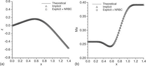
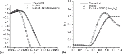
Although both the implicit and explicit methods converged to the theoretical A solution (), the implicit method showed a convergence time and residual one order of magnitude lower (). When moving to cascade L, only the implicit method could still converge (; ). The explicit solution in is diverging and has no significance. The explicit method worked with CFL < 2 Citation22, whereas the implicit worked with CFL = 300. No further improvement in the convergence speed of the implicit method was observed for higher CFLs. The authors instead found that, in the limit deflection region, the implicit method becomes unstable below CFL ≃ 100, unless the initial geometry already has a sufficiently high camber.
Table 1. Convergence histories for cascades A and L.
4.2. Design of a turbine stage
The second test case simply would like to show the feasibility of the proposed approach, with no other particular purposes. The designed turbine stage treats an air flow with unit inlet total quantities and overall 0.307 mass flowrate. The mass flowrate distribution along the outlet section is such that ϱu linearly goes from 0.261 at the hub to 0.188 at the tip. The inflow has no swirl and meridional ramp that linearly varies between the hub and tip slopes. The rotational shaft speed is about 0.3. For the rotor blade load at the various spanwise sections, a hyperbolic function of the spanwise coordinate η was assumed. For the stator blade load, the same hyperbolic law, but with the opposite sign, was used. The distribution of the blade load along the meridional chords of both the stator and rotor follows a similar law to (12). For the sake of simplicity, blockage effects were neglected and both the stator and rotor cambersurfaces were fastened to meridional leading edges with no lean. The overall loss of relative total pressure due to profile losses was set to 7.5 × 10⁻³ and 8.1 × 10⁻³ for each meridional streamline of the stator and rotor regions, respectively. Due to the relative coarseness of the mesh (36 streamwise points × 21 spanwise points for both the blade regions), an exact Gauss method, with CFL = 300, was used to solve the three linear systems of equations that arise from the implicit time discretization in the case of a single stage. However, a sufficient endwall refinement was introduced to accept option (ii) in Section 3.4, when discretizing Equation (11) in the endwall volumes.
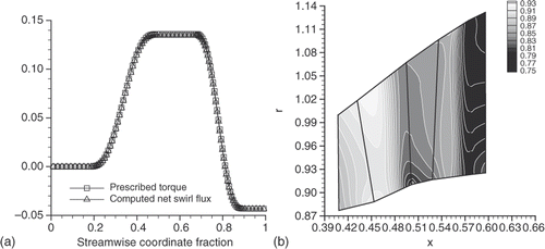
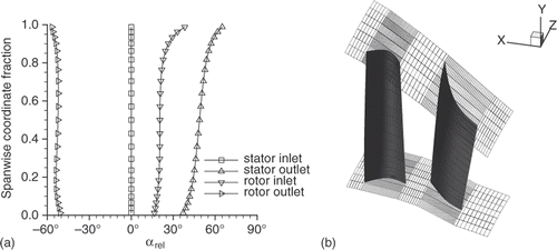
In order to assess the consistency of the design method, two quantities were compared along the streamwise coordinate ξ. The first quantity is the resultant axial torque that was given to the flow through the inviscid blade force between two circumferential sections, i.e. the inlet section of the stage and a generic streamwise section. The second quantity is the net swirl flux that was predicted by the inverse method between the same circumferential sections. The comparison shows an excellent agreement (). However, the predicted swirl flux also accounts for the contribution of the viscous blade force, which typically is two orders of magnitude lower than that of the inviscid force. maps the predicted static pressure in the entire flowpath. The static pressure along the outlet section does not follow the radially increasing profile that is consistent with the simple radial equilibrium equation. The hub-to-tip flow deflection goes from 37° to 65° for the stator and from 68° to 95° for the rotor (). shows the predicted three-dimensional geometry of the stator and rotor cambersurfaces.
4.3. Finite-span cascades
At high flow deflections, the two-dimensional implicit method still has shown some numerical instabilities that can be easily addressed by dealing with a single cascade of finite span. For this purpose, Equations (1–3) are expressed in Cartesian coordinates, as in the strictly one-dimensional problem, but keeping the spanwise velocity v and all spanwise derivatives ∂/∂y. However, if the endwalls are parallel to the x-axis and no spanwise variation is prescribed in boundary conditions, tangential blade force and leading edge coordinate, the flowfield and cambersurface still will be one-dimensional and described by the theoretical solution that was addressed in Section 2.1, although on a two-dimensional flowpath. In particular, options (ii) and (iii) in Section 3.4 are both rigorous, since v and fiy vanish at any point of the domain. The cambersurface–endwall orthogonality condition also reduces to ∂z/∂y = 0.
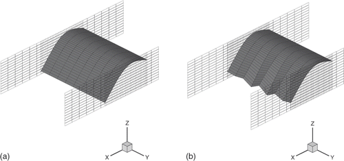
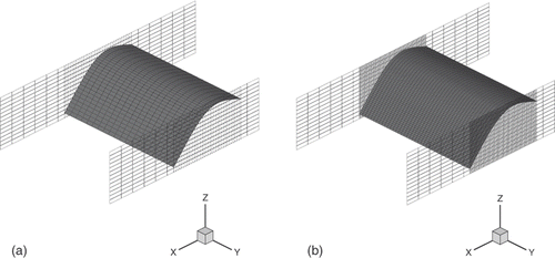
In the third test case, the two-dimensional solver was used to re-obtain cascade A in Sections 2.1 and 4.1, but with a unit span. Three computations were performed using a 36 × 9, a 36 × 21 and a 72 × 41 meshes in the blade region. Since the theoretical solution was assumed as the initial, the scheme could work below the lower stability limit that was found in Section 4.1. Therefore, the two linear systems of equations that update the flowfield and cambersurface geometry were solved by means of an effective alternate factorization technique, with CFL = 7.
Using the 36 × 9 mesh, the method was not able to maintain the theoretical solution throughout the computation, but the cambersurface began to spanwise wave in the trailing edge region (). On the other hand, the computations with 36 × 21 and 72 × 41 meshes remained perfectly stable, with no displacement from the theoretical solution (). The authors experienced the stable behaviour for more than 10 spanwise points, regardless of the streamwise point number. The same threshold on the spanwise mesh resolution was surprisingly observed when choosing any of options (i), (ii) and (iii) in Section 3.4. Only one way was found to make the two-dimensional solver stable with all deflection levels and spanwise resolutions, i.e. to adopt spanwise periodical boundary conditions for all governing equations (1–3).
4.4. Discussion
In the absence of endwalls, the implicit approach has allowed the authors to completely overcome the difficulties of the explicit reference schemes Citation6,Citation11,Citation13 when dealing with high-deflection solutions of the investigated inverse formulation. The implicit method effectively re-obtains any solution of the linear cascade problem along the constant flowrate load curves, up to the limit deflection and load values that are consistent with the specified mass flowrate. Even when coupled to non-reflective formulations of this outlet condition, explicit methods are far less effective in designing high-deflection cascades. Furthermore, the non-reflective boundary condition no longer works for outlet Mach numbers higher than 0.4–0.5, so that only the implicit approach seems to cope with turbine cascades in the high-subsonic range. This is the most prominent result of the present work.
Unfortunately, when endwalls are included in the computation the method does not always keep the same numerical properties with high flow deflections. Because of the new instabilities, it could be not possible to re-obtain some typical turbine configurations of the most recent aeronautical applications. These instabilities seem to be related to the mesh resolution in the spanwise direction. The authors believe that, using a coarse mesh, the numerical entropy production can make the actual limit loads significantly lower than the theoretical values that were addressed in Section 2.1. Therefore, the same blade can work more or less close to the actual limit conditions depending on the mesh resolution. Although the limit blade loads are not defined for the axisymmetric formulation of the inverse problem, 95° flow deflections were effectively obtained, when designing the complete turbine stage in Section 4.2, by means of a convenient mesh refinement near the endwalls. On the other hand, Section 4.3 shows that even 70° cannot be obtained if the mesh is too coarse. However, the treatment of the endwall volumes in Equation (11) does not seem to affect the stability of the two-dimensional solver. Section 3.4 explains that this treatment is ambiguous and can lead to a non-upwind approach, but the method showed the same stability limits for all the options that are addressed there. Only use of periodical boundary conditions for all the governing equations allowed the method to provide the desired geometry and flowfield for any deflection level and mesh resolution. Although the authors recognize that there is no physical reason for applying this periodicity condition, they draw the belief that coupling between the Euler and surface-flow slip equations must play a role as a source of instabilities along endwalls. There are other results supporting this belief. The authors adopted the same time-marching solution of Equation (11) in the context of an alternative inverse formulation where the tangential flow velocity, instead of the tangential blade force, is specified as the main design parameter. This formulation is more similar to that proposed in reference Citation4. It is described by the same set of Equations (1–3), though coupled in a different way. For one-dimensional isentropic flows such as the one in Section 4.3, the tangential velocity distribution that corresponds to the desired blade load distribution can be easily obtained from the third of Euler equations (4). When specifying the tangential velocity, the inverse method was found to be perfectly stable up to the limit load values, regardless of both mesh resolution and endwall treatment in Equation (11).
The lower stability limit CFL ≃ 100 that was observed in the one-dimensional test case can be considered a minor drawback of the proposed approach. The authors justify it by the need to skip the strong transients that arise when the initial geometry is not sufficiently cambered. Because of this limit, it could be not possible to solve the linear systems of equations that are led to by the implicit discretization of Equations (2) and (11) through approximate factorization techniques. Approximate factorizations do not usually allow CFLs higher than 10–15. In order to avoid more expensive exact or iterative techniques, the initial solution must be chosen as close as possible to the expected one. However, the gap in convergence speed between the implicit and explicit computations will not be as evident as in the one-dimensional case, where these systems come to a tridiagonal form and can be exactly solved using the effective Thomas algorithm.
Finally, it must be pointed out that the radial distribution of the mass flowrate at the outlet section of a single turbine stage, or a complete machine, cannot be ruled by the simple radial equilibrium equation, as the static pressure often does in turbomachinery practice. Therefore the predicted pressure distribution, though consistent with the physics of the axisymmetric flow as described by the complete set of Euler equations, may not show the typical behaviour of the simple radial equilibrium assumption.
5. Concluding remarks
An implicit upwind, finite-volume method has been proposed for the axisymmetric inverse design of axial flow turbines. This method predicts the flowfield and the geometry of the blade cambersurfaces for a specified blade load distribution. The implicit method:
| • | is able to effectively obtain any infinite-span turbine cascade, up to sonic outlet conditions; | ||||
| • | was shown to have a convergence time and residual that are one order of magnitude lower than previous explicit methods, when dealing with infinite-span turbine cascades in the low-subsonic range; | ||||
| • | does not keep the same numerical properties when dealing with high-flow deflections in the presence of endwalls, at least for spanwise coarse meshes. | ||||
Acknowledgements
This work has been partly funded by the Regione Piemonte Italy (Bando regionale 2004–E57 and Bando regionale 2006–CORALE) and partly by the Avio Group Italy.
References
- Denton, JD, and Dawes, WN, 1999. Computational fluid dynamics for turbomachinery design, Proc. IMechE Part A: J. Mech. Eng. Sci. 213 (1999), pp. 107–124.
- Petrovic, MV, Dulikravich, GS, and Martin, TJ, 2001. Optimization of multistage turbines using a through-flow code, Proc. IMechE Part A: J. Power Energy 215 (2001), pp. 559–569.
- Yao, Z, and Hirsch, Ch, 1995. Throughflow model using 3D Euler or Navier–Stokes solvers, Turbomachinery–Fluid Dynamic Thermodyn. Asp. VDI Berichte 1185 (1995), pp. 51–61.
- Damle, SV, Dang, TQ, and Reddy, DR, 1997. Throughflow method applicable for all flow regimes, Trans. ASME J. Turbomachinery 119 (1997), pp. 256–262.
- Sturmayr, A, and Hirsch, Ch, 1999. Throughflow model for design and analysis integrated in a three-dimensional Navier–Stokes solver, Proc. IMechE Part A: J. Power Energy 213 (1999), pp. 263–273.
- Bena, C, Larocca, F, and Zannetti, L, Design of Multi-stage Axial Flow Turbines and Compressors. Presented at IMechE 3rd European Conference on Turbomachinery. London, UK, 1999.
- Simon, J, and Léonard, O, A Throughflow Analysis Tool Based on the Navier–Stokes Equations. Presented at ETC 6th European Conference on Turbomachinery. Lille, France, 2005.
- Croce, G, Gazano, R, Satta, A, and Ratto, L, Axisymmetric Navier Stokes Solution for Turbomachinery Computations. Presented at ISABE 19th Conference on Air Breathing Engines. Montréal, Canada, 2009.
- Dang, T, and Isgro, V, 1995. Euler-based inverse method for turbomachine blades, Part 1: Two-dimensional cascades, AIAA J. 33 (1995), pp. 2309–2315.
- Larocca, F, 2008. Multiple objective optimization and inverse design of axial turbomachinery blades, J. Propulsion Power 24 (2008), pp. 1093–1099.
- Zannetti, L, and Pandolfi, M, 1984. Inverse design technique for cascades, NASA CR-3836 (1984).
- Ferlauto, M, Iollo, A, and Zannetti, L, 2004. Set of boundary conditions for aerodynamic design, AIAA J. 42 (2004), pp. 1582–1592.
- Zannetti, L, and Larocca, F, 1990. Inverse methods for 3D internal flows, AGARD-R-780 (1990).
- Rudy, DH, and Strickwerda, JC, 1980. A non reflecting outflow boundary condition for subsonic Navier–Stokes calculations, J. Comput. Phys. 36 (1980), pp. 55–70.
- Rosa Taddei, S, and Larocca, F, 2008. Axisymmetric design of axial turbomachinery: an inverse method introducing profile losses, Proc. IMechE Part A: J. Power Energy 222 (2008), pp. 613–621.
- Rai, MM, and Chackravarthy, SR, 1986. An implicit form for the Osher upwind scheme, AIAA J. 24 (1986), pp. 735–743.
- McDonald, H, and Briley, WR, 1979. Computational fluid dynamic aspects of internal flows, AIAA Paper 79-1445 (1979).
- Chackravarthy, SR, and Osher, S, 1983. Numerical experiments with the Osher upwind scheme for the Euler equations, AIAA J. 21 (1983), pp. 1241–1248.
- Deconinck, H, 1987. A survey of upwind principles for the multidimensional Euler equations, Computational Fluid Dynamics (1987), VKI LS 1987-04, Rhode-St-Genèse (BE).
- Chackravarthy, SR, 1983. Euler equations–Implicit schemes and boundary conditions, AIAA J. 21 (1983), pp. 699–706.
- Ghaly, WS, 1990. A design method for turbomachinery blading in three-dimensional flow, Int. J. Numer. Methods. Fluids 10 (1990), pp. 179–197.
- Mascio, ADi, 1992. Simulazione di flussi vorticosi mediante il modello di flusso comprimibile non viscoso. Ph.D. Diss.. Università di Roma (I); 1992.
Appendix
A1. Symbols
| x, r | = | axial, radial coordinates |
| ϑ, z | = | tangential coordinate |
| ξ, η | = | computational coordinates |
| i, j, k | = | axial, radial, tangential unit vectors |
| t | = | time |
| V | = | velocity vector |
| u, v, w | = | axial, radial, tangential velocities |
| = | covariant velocity components | |
| β | = | ramp flow angle, β = arctan(v/u) |
| α | = | blade-to-blade flow angle, |
| λ | = | wave speed |
| Ma, a | = | Mach number, sound speed |
| ϱ, p, T | = | density, pressure, temperature |
| E, H, S | = | internal energy, enthalpy, entropy |
| γ | = | specific heat ratio, γ = 1.4 |
| f | = | volume force vector |
| Fi | = | blade load |
| ω | = | rotational speed |
| h | = | metal blockage factor |
| δ, N, σ | = | blade thickness, blade number, cascade solidity |
| Δσ, Δℓ | = | volume area, volume side |
A2. Subscripts and superscripts
| x, r | = | axial, radial components |
| ϑ, z | = | tangential component |
| i, v | = | inviscid, viscous |
| exh | = | exhaust |
| inl, out, le, te | = | inlet, outlet, leading edge, trailing edge sections |
| hub, tip | = | hub, tip |
| lim | = | limit conditions |
| rel | = | relative quantities |
| 0 | = | total quantities |
A3. Abbreviations
| CFD | = | computational fluid dynamics |
| TVD | = | total variation diminishing |
| ENO | = | essentially non oscillatory |
| CFL | = | Courant–Friedrichs–Lewy parameter |
| NRBC | = | non-reflective boundary conditions |
| RMS | = | root mean square |
Appendix
B1. Transformation from primitive variable to fluxes
The basic thermodynamic relations
provide, for the flux vector {F} = ϱu (1 p/ϱu+u w H0)T, the Jacobian matrix
B2. Transformation from conservative variables to primitive variables
By writing the conservative-variable vector {W} = ϱ (1 u w E0)T and the primitive-variable vector {U} = (a u w S)T in the forms
the following Jacobian matrix is obtained:
where
.
B3. Approximate solution of the Riemann problem
The following Jacobian matrices are obtained for the regions i + 2/5 and i + 3/5 from Osher's solver equations Citation18, together with the assumption w = const along the u waves:
The relations for the sonic regions i + 1/5 and i + 4/5 provide
