Abstract
This article investigates an inverse problem for hydro-mechanically coupled systems. The task is to identify damaged zones in water dams out of combined hydrologic and mechanical measurements. Even though water dams are generally well monitored, there is little data available to precisely describe the fluid and stress fields in the structure due to inhomogeneous distributions of the material. Over the lifetime of the dams, which can exceed 100 years, the condition of the structures may change remarkably due to aging, chemical weathering and cracking. Highly fissured regions may arise. Our goal is to identify the damaged zones by comparing the numerically computed fluid and stress fields with measurements along the boundaries. The identification is shown to be an ill-posed problem. For the inversion, regularizing iterative methods need to be applied, in which modified implementations of the Landweber method are used. The computation of the adjoint of the linearization of the parameter-to-solution mapping is done analytically. Due to the consideration of a multi-field problem, numerical results show that the identification results are significantly improved compared to the results of single-field problems.
1. Introduction
Construction processes in civil engineering are increasingly supported by simulation models. The solution of many of these models consists of several physical quantities. For example, numerical models for water dams, embankments and subsoils include the mechanical, hydraulic and thermal fields. The precision of the output of these models depends on both the correct choice of the model and the correct adaptation of the model parameters. A careful model and material parameter adaptation to available measurements needs to be conducted. This article is devoted to an inverse problem for a hydro-mechanical problem, namely the identification of material inhomogeneities within the structures by evaluating combined hydraulic and mechanical measurements.
The system identification considered in this article can also be regarded as a method to monitor the embankment's condition. Undamaged systems have a homogeneous distribution of the material properties according to their construction process. However, damaged systems consist of one or several subdomains where the material properties differ remarkably within the structure due to partial cracking, weathering, elution or chemical reactions. Early recognition of such damaged zones is particularly essential in order to avoid seepage, piping and potential failure of the structure.
In the following, the identification of damage corresponds to the simultaneous determination of two material coefficients in a coupled parabolic system of partial differential equations. Related works treating coefficient determination problems for single-field parabolic problems can be found in Citation1–9 and references therein. For coupled-field parameter identification problems, we refer in particular to Citation10, where coupled groundwater flow and mass transport problems and general coupled problems are discussed.
The identification of damage, inhomogeneous stiffness properties and calibration of Finite Element models in dams is reported (e.g. Citation11–17). All these works, however, are restricted to measurements and observations of static or dynamic mechanical quantities.
To the author's knowledge, the consideration of both hydraulic and mechanical data to assess the dam's properties and the treatment of damage by heterogeneous parameter distributions is a new approach and has not yet been proposed in the literature.
The Landweber iteration, which is used in this work to solve the inverse problem of crack detection, was proven to converge for linear compact operators by Landweber Citation18. The convergence theory for the nonlinear problem has been developed by Binder et al. Citation19 and Hanke et al. Citation20. The application of Morozov's discrepancy principle Citation21 as a stopping rule is treated in Citation22,Citation23. The nonlinear Landweber iteration with flexible steplength as used in this work is investigated in Citation24,Citation25. For a survey of the Landweber iteration and its modifications, see Citation26. Landweber iteration is applied in many inverse problems occurring, for example, in image restoration Citation27 and inverse conductive scattering problems Citation28. The method has also been successfully applied to the recovery of parameter nonlinearities, e.g. heat transfer coefficient in Citation29 or nonlinear permittivity and piezoelectric coupling in Citation30 or nucleation and growth rates of polymer crystallization processes Citation31.
The article is organized as follows. Section 2 describes a simple case of fluid-solid interaction for small strain situations. A set of partial differential equations is derived. In Section 3, a numerical scheme for the inverse problem is presented, in which we apply an iterative regularizing scheme. The gradient is computed by solving a coupled adjoint state problem during each iteration step. In Section 4, numerical results are given.
2. Coupled flow and solid deformation
In this section, balance and constitutive equations are introduced which describe a simple form of fluid-flow through porous media. Out of these equations, a set of partial differential equations is then derived. In order to model cracks and damaged zones in the computational domain, a smeared crack model is considered, i.e. the most highly influencing material parameters are assumed to be continuously spatially varying quantities. For works that discuss discrete modelling of cracks in water dams, see, e.g. Citation32–34.
In the sequel, we consider a one-phase flow (water) through a deforming, fully saturated medium. Although we are aware of the fact that this scenario is not perfectly suitable for the simulation of water dams, we wish to keep the representation as simple as possible. Future work will be devoted to incorporating the empirical functions of van Genuchten Citation35, which describe the nonlinear relation between permeability and saturation, as well as saturation and suction. Since the task of this work is to develop a scheme which is capable of identifying material inhomogeneities, this simple approach serves the purpose sufficiently. Possible thermal effects are also neglected and the material is assumed to be isotropic.
The hydromechanical system is characterized by the deformation of the solid together with the flow of the fluid through the pores and the effects of pore water pressure distribution on the stress state of the structure. This kind of coupling is usually referred to as primary consolidation in soil mechanics Citation36.
Setting up the mathematical model of fluid flow-structure interactions involves the momentum conservation law, i.e.
(1)
where σ denotes the macroscopic total stress tensor (N m−2) and g is the acceleration due to gravity (m s−2). The averaged density ρa ≔ ((1 − n)ρs + nρw) (kg m−3) of the porous medium is determined from the densities of the solid ρs and the fluid ρw; n denotes the porosity. The operator ℬ is the strain-displacement differential operator
Additionally, the mass balance of the liquid needs to be fulfilled, i.e.
(2)
Here
, where Ks and Kw are the bulk moduli (N m−2) of the solid and water, respectively, and α denotes Biot's constant (dimensionless). Furthermore, u is the mechanical displacement vector (m), pw liquid phase pore pressure (here water) (N m−2) and
(see, e.g. Citation36). The term
in (2) describes the effect of the volumetric strain rate on the pore pressure distribution.
The flow of the fluid is mainly characterized by the phenomenological law of Darcy. It states that the relative mass flux of the liquid is proportional to the negative gradient of the liquid pore pressure pw, Citation36,Citation37
(3)
Here, qrw (kg m−2s−1) denotes the relative mass flux of the fluid. The isotropic intrinsic permeability tensor is given by
(4)
where krw is the relative liquid permeability (m2), μw is the liquid's viscosity (N m−2 s−1). On the mechanical side, the coupling between the hydraulic and mechanical quantities is described by the effective stress law which considers the additional contribution from the pore water pressure to the normal components of the mechanical stresses
(5)
In (5) σ′′ denotes the effective stress tensor.
The elastic behaviour of the structure is mainly described by Hooke's law
where
is the modulus of elasticity and δij is Kronecker's delta.
The Lamé parameters
(6)
are themselves determined by Young's modulus E (N m−2) and Poisson's ratio ν.
The damaged zones in the dam are described by a smeared crack model, i.e. the main parameters, Young's modulus E in (6) and hydraulic conductivity k in (4) are spatially varying functions with H1 regularity (one-time weakly differentiable)
(7)
Expressing the theory above solely in dependence of the unknowns, mechanical displacement u and liquid pore pressure pw, we obtain the following set of partial differential equations:
(8)
with boundary conditions
(9)
and initial conditions
(10)
In (9)
and N = (nx, ny, nz) is the outer unit normal vector.
Solving the system in (8) with (9) and (10) will be referred to hereafter as the forward problem.
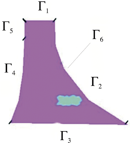
In this work a situation of plain strain is considered. shows the schematic shape of the computational domain Ω, which represents a profile of a gravity water dam. The upstream side is on the left-hand side. The boundary is divided into five subboundaries, i.e. ∂Ω = Γ1 ∪ Γ2 ∪ Γ3 ∪ Γ4 ∪ Γ5 is indicated, too. The additionally sketched boundary Γ6 consists of just one point and is regarded in Section 3 where an additional measurement is taken. The inhomogeneous Dirichlet boundary condition h in (9) simulates different filling levels of the reservoir.
Figure 1. Profile of gravity water dam. The location of the damaged zone is indicated with the boundaries labelled accordingly. The height of the modelled dam is about 29 m, the crest has a length of 166 m and the radius of curvature is about 120 m.
The numerical solution of the forward problem is done with the Finite Element Method where standard nodal finite elements are applied for the spatial discretization.
In order to derive the Finite Element formulation, the first equation in (8) is tested with vector valued functions having compact support, where
and
The second equation in (8) is tested with scalar
functions. In order to obtain an algebraic equivalent of (8), Green's first integration theorem is applied to the resulting equations. The following FE approximation for the unknowns is then introduced
(11)
where Nu and Np are elements of bases of (Sh)3 and Th which are finite dimensional subspaces of
and
. The number of nodes in the FE-mesh, on which no homogeneous Dirichlet boundary conditions are defined, is denoted by neq.
The nodal displacements and nodal pore pressures
are now obtained by solving
or after symmetrization according to Citation36
The element matrices are computed as follows
Qe = ∫Ωe (ℬNu)T αmNp dΩ (hydro-mechanical coupling matrix) | |||||
Ke = ∫Ωe(ℬNu)T c(x)ℬNu dΩ (mechanical stiffness matrix) | |||||
| |||||
| |||||
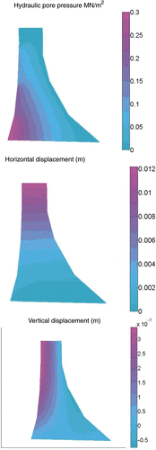
For the discretization in time, the generalized trapezoidal method – an implicit time-stepping scheme – is applied Citation36,Citation38. shows the pore pressure distribution and the horizontal and vertical component of the mechanical displacement at the final time t = T, where the water level lies between Γ4 and Γ5.
3. The inverse problem
This section deals with the inverse problem, i.e. the detection of the damaged zone within the dam structure out of the combined pore pressure and mechanical displacement measurements.
3.1. Measurements
It is assumed that over time the evolution of the mechanical displacement at the dam crest (two points) and on one point along the downstream side are recorded as follows
(12)
Additionally, it is assumed that there are five available hydraulic pore pressure measurements at the dam's foot
(13)
In the sequel, the measurements are stored in
. Here and also in Equations (12) and (13), the superscribed δ emphasizes the fact that measurements are generally distorted by a certain amount of noise. The δ is introduced as L2 measure of the noise level, i.e.
Whenever identification is done with noiseless data, the superscribed δ is dropped: y = yδ for δ = 0.
The actual discrete measurements given along the boundaries Γ1 and Γ3 are linearly interpolated. This is why measurements are considered not only at discrete points, but along the boundaries, as well. At Γ6 a single measurement point is considered. The hydraulic quantities are recorded by pore water pressure transducers which are located at the dam's foundation. The values obtained from these transducers are generally used to determine the reduction of the hydraulic potential in the water dam (see, e.g. Citation39,Citation40). The mechanical displacements at the crest of the dam and the downstream side are dictated either by plumb line or hanging pendulum (horizontal displacement), geometrical precision, differential levelling or geodetic positioning.
3.2. Mathematical formulation
The measurements ūδ and are assumed to be functions in L2([0, T], L2(Γi)), i ∈ {u, p}. The most important instrument in inverse analysis is the so-called parameter-to-solution mapping
(14)
which relates the sought-for quantities to the measurements. The inverse problem with given measured data yδ corresponds to solving
(15)
where p ≔ (E, k)T.
During the inversion, i.e. the solution of (15) one computes values in H1 out of noisy measurements in L2. Due to the lack of regularity in the measured data and the fact that the measurements may not be attainable by F, the inversion needs to be regarded as an ill-posed problem. The lack of stability is a severe problem, as small error components in the measured data may lead to large identification errors.
3.3. Inversion
For the stable solution of the inverse problem, iterative regularizing methods are well proven, e.g. the nonlinear Landweber method Citation20 and its modifications Citation24–26, for n = 1, … , n*(δ, yδ)
(16)
Even though the measured data yδ may not be in the range of F and the iterates pn,δ do not converge to the exact solution p†, the method in (16) allows for a stable approximation of p†.
In order to implement the Landweber method efficiently, the following three questions must be answered:
| 1. | How do we choose the relaxation parameter ω in (16) to guarantee convergence which is sufficiently fast? | ||||
| 2. | How do we determine the stopping index n*(δ, yδ) which influences the trade-off between accuracy and stability? | ||||
| 3. | How do we compute the adjoint F′(p)*(r) of the linearized operator F′(p)[dp] applied on a residual r? | ||||
| 4. | Which rates of convergence can we expected? | ||||
3.3.1. Relaxation parameter
In order to guarantee convergence of the method in (16), the relaxation parameter ω needs to be chosen such that
(17)
for all p ∈ ℬ2ρ(p0), where ℬ2ρ(p0) denotes a closed ball of radius 2ρ around the initial guess p0. By guaranteeing that (17) is fulfilled, one implements the classical Landweber iteration Citation20,Citation26.
Alternatively, one can apply the minimal error method which is a variant of Landweber's iteration with a flexible choice of the relaxation parameter ω ≔ ωn,δ Citation24,Citation25 with
(18)
The numerator and denominator in (18) are quantities which need to be computed anyway during the iteration (16). This can effectively improve the convergence of the Landweber method without increasing the computational efforts.
3.3.2. Regularization by a posteriori stopping
In order to avoid an amplification of the data error, the iteration in (16) is stopped by a generalized discrepancy principle, i.e. when for the first time
(19)
holds for τ > 2 (see Citation20,Citation26). The last index n, for which (19) holds, is n*(δ, yδ). It is shown that an early stopping according to (19) renders the Landweber method a regularizing method Citation20,Citation26,Citation41, i.e. it guarantees that the solution is stably dependent on the measured data.
3.3.3. Computation of the adjoint problem
The adjoint F′(p)*(r) is given implicitly via the solution of a coupled hydro-mechanical set of differential equations.
Proposition 3.1
If we assume that the operator F defined in (14) is Fréchet differentiable, then the adjoint of the linearization of F is given by
(20)
where (ϕ, ψ) are solutions of the following adjoint system of partial differential equations
(21)
The operator Φ : 𝒟(Φ) = {ρ ∈ H2(Ω) | ∇ρ = 0 on ∂ Ω} → L2(Ω) in (20) is the adjoint of the embedding operator from H1(Ω) into L2(Ω) where Φ is defined as
(22)
Proof
The Fréchet derivative of F is given by the limit
(23)
where (du, dpw)T is the solution of the following system:
(24)
with the following boundary conditions:
(25)
and initial conditions
(26)
In (24) and (25) dc and dk are the stiffness and conductivity tensors computed with an incremented Young's modulus E + dE and hydraulic permeability k + dk, respectively. The adjoint of F′ is now given implicitly via the following identity:
(27)
In order to obtain an explicit representation of the adjoint, we multiply the two equations in (24) with a sufficiently smooth vector-valued function ϕ ∈ Ω × [0, T] and a scalar function ψ ∈ Ω × [0, T] respectively, integrate over space and time and add the resulting equations
(28)
Integrating with respect to space and time and rearranging the resulting equations in such a way that the terms du and dpw can be factored out, gives
(29)
(30)
(31)
(32)
(33)
(34)
(35)
The terms in the rounded brackets in Equations (29) and (30) define the partial differential equations of the adjoint system given in (21). The entries in Equations (32) and (34) vanish due to the definition of the Neumann boundary conditions in (25). The contribution of the integral in (33) equals zero due to the prescribed end condition ψ(T) = 0 in (21) and the prescribed initial conditions dpw(0) = 0 and du(0) = 0 in (26).
Writing down the remaining terms results in the following integral equality:
(36)
Let us rewrite the residual in (16) as follows: F(pn,δ) − yδ = (ru, rp)T, where
and
, set NT(cℬϕ) = ru and
along the boundaries Γu and Γp, respectively, and NT(cℬϕ) = 0 and
at the boundaries ∂Ω ∖ Γu and ∂Ω ∖ Γp.
Then
(37)
A comparison of (37) with (27) and the application of Φ−1 implies (21).
The definition of Φ as in (22) is due to the fact that for any b ∈ H1, the following holds:
(38)
▪
Note, in particular, that the adjoint system has an end condition. It is, therefore, a well-posed initial-boundary value problem which is solved backwards in time. Introducing the following time transformation τ = T − t, the adjoint problem can be transferred into an initial-time problem with time variable τ. The solutions are then retrieved by ϕ(x, t) = ϕ(x, T − τ) and ψ(x, t) = ψ(x, T − τ).
If and
in the case of noiseless data, where u and pw solve (8) with E(x) and k(x), then F′(E, k)*(ru, rp) = 0 and E(x) and k(x) are minimizers of ‖F(E, k) − y‖2.
For a detailed discussion on the computation of an adjoint problem for the identification of the diffusion coefficient in a linear (non-coupled) parabolic equation, see Citation8 and for coupled problems see Citation10. The Finite Element Method is also applied to solve the derived adjoint system which results in the algebraic system
with right-hand sides according to the natural boundary conditions in (21).
We want to emphasize that, during each iteration step, all nodes of the parameterized distributions of E and k are updated by just one forward and adjoint problem call. This is especially superior to any gradient computation with finite difference approximations where the forward problem needs to be solved M + 1 times, when M is the number of nodes of the parameterization of E and k.
3.3.4. Convergence
In order to study the convergence of the Landweber method, one needs to assume that F is Frèchet-differentiable with ‖F′(·)‖ ≤ 1 and that
(39)
holds in 𝒟(F). Then, for any solution p ∈ 𝒟(F) of F(p) = y a sufficient condition for pn+1,δ to be a better approximation of the exact solution denoted by p† is that
which also gives an estimate for the factor τ in (19). However, the condition in (39) most likely cannot be shown rigorously for the coupled identification problem here. Nonetheless, it is proven to hold for the parameter estimation problem in an uncoupled elliptic problem Citation26 and a harmonic problem in Citation30.
Convergence rates of Landweber iteration can only be shown if a source condition of the following type
(40)
is additionally fulfilled Citation20,Citation26. The source condition implies a certain smoothness for the difference p† − p0 for many examples if μ > 0. Under a further restriction of the nonlinearity of F, namely F′(p) = Rp F′(p†), where Rp is a family of bounded linear operators with ‖Rp − I‖ ≤ C‖p − p†‖, the rate of convergence can be shown to be
(41)
The stopping index n*(δ, yδ) is obtained by (19) and can be estimated in the following manner
(42)
For the special case
in (40), the terms in (41) and (42) reduce to
(43)
which is the best possible rate of convergence to be expected. The condition in (40) means that one has to know all rough parts of the sought-for quantities up to a certain regularity in order to obtain the rate
. However, the smoothness assumed on the difference p† − p0 will hardly be fulfilled in the application example given here. Therefore, we expect a slower convergence during the numerical computations.
For the minimal error method convergence rates have only been proven in the case of exact data, i.e. for δ = 0. In this case, for the modified Landweber method with flexible relaxation parameter according to (18), one has (see, e.g. Citation25).
(44)
4. Numerical results
This section discusses some numerical results obtained by the application of the inversion scheme. All results are obtained by evaluating synthetically generated data. These data are obtained by solving the forward problem with known parameter distributions. The solutions of the forward problem are then distorted by a one percent normally distributed noise term in order to model measurement errors. The generation of these synthetic measurements is performed on a fine mesh with 576 finite elements, whereas the reconstruction of the damaged zones is performed on a coarser mesh with 144 elements in order to avoid an inverse crime Citation42. An inverse crime is committed when almost the same computational models are used to both synthesize and invert data in an inverse problem. This must be avoided as the results may appear too optimistic.
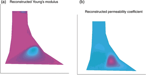
The initial guess is a homogeneous distribution of the material parameters E and k. The exact solution, i.e. the location of the crack, is depicted in . In the following, we applied two strategies. In the first, both parameters E and k have been updated independently, i.e. we solved the adjoint problem and obtained parameter increments for both, the permeability and Young's modulus in each iteration step in (16). shows the uncorrelated reconstruction results. The damaged location, i.e. the distribution of Young's modulus in and the distribution of the permeability in , is identified acceptably well. However, as we see, the shape and location of the damage according to the distribution of E and k are not exactly the same. Also the reconstruction of Young's modulus could lead us to guess that there is another crack close to the dam crest, which is not the case according to the results of the permeability. In the second strategy, we consider the correlation of the sought-for quantities.
Figure 3. (a) Initial guess (homogeneous material distribution). (b) True solution, i.e. the location of the damage.
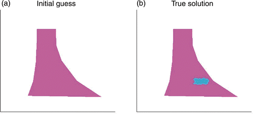
Figure 4. Reconstruction results where both E(x) (a) and k(x) (b) have been updated independently by the iteration in (16).
Now, the obtained results are combined immediately in the following manner:
(45)
in every step in (16), where the newly introduced parameter χ serves as an indicator of damage. The constants γE and γk compensate for the different orders of magnitude of E and k. On the left-hand side of , the distribution of the parameter χ is shown, which gives a more precise reconstruction result due to the correlation of the parameters. The sharp boundaries around the damaged zone in the right-hand side of in are obtained by projecting the identified values of χ which exceed (or fall below) a certain value to one (or zero). This threshhold is found by indicating positions where the gradient of χ becomes large, i.e. where a remarkable change in the structure of the dam is observed. Numerical computations reveal that the successful identification of material inhomogeneities strongly depends on the location of the inhomogeneity and, in particular, on the distance between damage and measurements. Obviously, a crack close to the tip of the dam is mainly identified via the mechanical quantities (see ).
Figure 5. Reconstruction results. (a) Distribution of parameter χ(x) according to (45). (b) Sharpened solution.
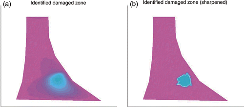
Figure 6. Location and identification, i.e. the distribution of the parameter χ(x) according to (45), of a crack close to the dam's tip.
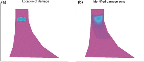
The single mechanical measurement along the boundary Γ6 (see ) turns out to be indispensable for the identification of the cracked zone in both examples. Cracks close to the upstream side of the dam are observed to be less precisely identifiable than those on the downstream side. This is due to the lack of mechanical measurements under the water. However, these partially dissatisfying results can give valuable hints as to where different sensors can be properly placed along or within existing dam structures. As a consequence, the example may be further investigated to answer questions concerning optimal experimental design for hydromechanically coupled problems in the field of civil engineering.
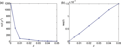
Finally, results concerning convergence of the implemented scheme when data errors occur in the measurements are given in and . In , the norm of the difference between the identified and the exact parameters over an increasing noise level is plotted. shows the decreasing number of iterations for increasing noise level (). The linear relation between the residual and noise level () is given by the stopping rule in (19). The numerical convergence results are consistent with the theory given in Equation (43).
Figure 7. (a) Error eE(δ) ≔ ‖E† − En*(δ,yδ),δ‖ over increasing data noise δ. (b) Error ek(δ) ≔ ‖k† − kn*(δ,yδ),δ‖ over increasing data noise δ.
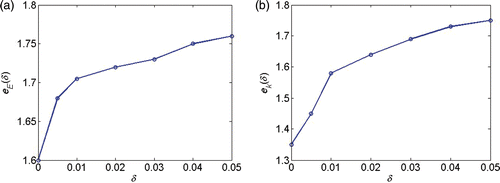
Figure 8. (a) Number of iterations n*(δ, yδ) for different noise levels δ. (b) Residual res(δ) = ‖F(pn,δ) − yδ‖ over δ.
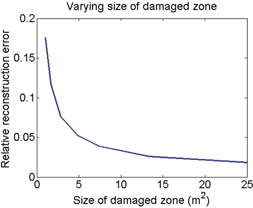
Aside from the noise level and the distance of the damage to the measurements, the size of the damaged zone strongly influences the quality of the identification results. Obviously, a small crack only slightly influences the fluid and mechanical fields and therefore, there is little to measure that could indicate damage. displays the relation between the size of the damaged area and the quality of the identification.
5. Summary and outlook
This work presents a numerical scheme for the identification of irregular material distributions in coupled hydro-mechanical systems. Furthermore, it demonstrates that more information is gained by evaluating data from the two physical fields involved. Future research will be devoted to the description of the fluid-flow in the dam by considering the effects of partially saturated media which incorporate the nonlinear relationships between saturation and suction such as permeability and suction (see Citation35). Additionally, the procedure will be applied to measurements of arch type gravity dams run by the Ruhrverband Essen in Germany.
As mentioned above, the results of this work can be further explored for an optimal experimental design, offering clues as to where measurement devices should be optimally located and how many of them are required in order to detect damage in all parts of the structure reliably.
Acknowledgements
The author gratefully acknowledges the support of the German Research Foundation (DFG) through the Research Training Group 1462. Furthermore, the author wishes to kindly thank Professor C. Könke and Professor T. Schanz for their motivation and initialization of this research.
References
- Cannon, JR, and DuChateau, P, 1987. Design of an experiment for the determination of a coefficient in a nonlinear diffusion equation, Int. J. Eng. Sci. 25 (1987), pp. 1067–1078.
- DuChateau, P, 1995. Monotonicity and invertibility of coefficient-to-data mappings for parabolic inverse problems, SIAM L. Math. Anal 26 (1995), pp. 1473–1487.
- DuChateau, P, 1997. An inverse problem for the hydraulic properties of porous media, SIAM J. Math Anal 28 (1997), pp. 611–632.
- DuChateau, P, Thelwell, R, and Butters, G, 2004. Analysis of an adjoint problem approach to the identification of an unknown diffusion coefficient, Inverse Problems 20 (2004), pp. 601–625.
- Hanke, M, and Scherzer, O, 1999. Error analysis of an equation error method for the identification of the diffusion coefficient in a quasilinear parabolic differential equation, SIAM J. Appl. Math 59 (1999), pp. 1012–1027.
- Knabner, P, and Bitterlich, S, 2002. An efficient method for solving an inverse problem for the Richards equation, J. Computational Applied Mathematics 147 (2002), pp. 153–173.
- Richter, GR, 1981. Numerical identification of a spatially varying diffusion coefficient, Math. Comput 36 (1981), pp. 375–386.
- Hasanov, A, Duchateau, P, and Pektacs, B, 2006. An adjoint problem approach and coarse-fine mesh method for identification of the diffusion coefficient in a linear parabolic equation, J. Inv. Ill-Posed Problems 14 (5) (2006), pp. 435–463.
- Gottlieb, J, and Dietrich, P, 1995. Identification of the permeability distribution in soil by hydraulic tomography, Inverse Problems 11 (1995), pp. 353–360.
- Sun, Ne-Zheng, 1994. Inverse Problems in Groundwater Modelling. Vol. 6. Dordrecht Boston London: Kluwer Academic Publishers; 1994. pp. 114–140.
- Wang, BS, and He, ZC, 2007. Crack Detection of arch dam using statistical neural network based on the reductions of natural frequencies, J. Sound Vibration 302 (2007), pp. 1037–1047.
- Loh, CH, and Wu, TS, 1996. Identification of Fei-Tsu arch dam from both ambient and seismic response data, Soil Dyn. Earthquake Eng. 15 (1996), pp. 465–483.
- Ardito, R, and Cocchetti, G, 2006. Statistical approach to damage diagnosis of concrete dams by radar monitoring: Formulation and a pseudo-experimental test, Eng. Struct. 28 (14) (2006), pp. 2036–2045.
- Alves, SW, and Hall, JF, 2006. System identification of a concrete arch dam and calibration of its finite element model, Earthquake Eng. Struct. Dyn. 35 (11) (2006), pp. 1321–1337.
- Fedele, R, Maier, G, and Miller, B, 2005. Identification of elastic stiffness and local stresses in concrete dams by in situ tests and neural networks, Struc. Infrastruct. Eng.: Maintenance, Manage., Life-Cycle 1 (3) (2005), pp. 165–180.
- Bond, LJ, William, U, Kepler, F, and Frangopol, DM, 2000. Improved assessment of mass concrete dams using acoustic travel time tomography. Part I - theory, Construction and Building Materials 14 (2000), pp. 133–146.
- Bond, LJ, William, U, Kepler, F, and Frangopol, DM, 2000. Improved assessment of mass concrete dams using acoustic travel time tomography. Part II – application, Construct. Build. Materials 14 (2000), pp. 147–156.
- Landweber, L, 1951. An iteration formula for Fredholm integral equations of the first kind, Amer. J. Math. 73 (1951), pp. 615–624.
- Binder, A, Hanke, M, and Scherzer, O, 1996. On the Landweber iteration for nonlinear ill-posed problems, J. Inverse Ill-Posed Probl. 4 (1996), pp. 381–201.
- Hanke, M, Neubauer, A, and Scherzer, O, 1995. A convergence analysis of the Landweber iteration for nonlinear ill-posed problem, Numer. Math. 72 (1995), pp. 21–37.
- Morozov, VA, 1966. On the solution of functional equations by the method of regularization, Soviet Math. Dokl 7 (1966), pp. 414–417.
- Vainikko, GM, 1980. Error estimates of the successive approximation method for ill-posed problems, Automat. Remote Control 40 (1980), pp. 356–363.
- Defrise, M, and De Mol, C, 1987. "A note on stopping rules for iterative regularization methods and filtered SVD". In: Sabatier, PC, ed. Inverse Problems: An Interdisciplinary Study. London, Orlando, San Diego, New York: Academic Press; 1987. pp. 261–268.
- Scherzer, O, 1996. A convergence analysis of a method of steepest descent and a two-step algorithm for nonlinear ill-posed problems, Numer. Funct. Anal. Optim. 17 (1996), pp. 197–214.
- Neubauer, A, and Scherzer, O, 1995. A convergent rate result for a steepest descent method and a minimal error method for the solution of nonlinear ill-posed problems, ZAA 14 (1995), pp. 369–377.
- Kaltenbacher, B, Neubauer, A, and Scherzer, O, 2008. Iterative Regularization Methods for Nonlinear Ill-Posed Problems. Walter de Gruyter: GmbH; 2008.
- Yang, W, Cai, C, Ding, M, and Zhou, C, 2008. An Improved Landweber Method for Restoration of Aero-Optically Degraded Images, Comput. Sci. Software Eng. 6 (2008), pp. 125–128.
- Hettlich, F, 1998. The Landweber iteration applied to inverse conductive scattering problems, Inverse Problems 14 (4) (1998), pp. 931–947.
- Janicki, M, and Kindermann, S, 2009. Recovering temperature dependence of heat transfer coefficient in electronic circuits, Inverse Problems in Science and Engineering 17 (2009), pp. 1129–1142.
- Lahmer, T, 2008. "Forward and Inverse Problems in Piezoelectricity". In: PhD Thesis. Erlangen-Nuremberg: University of; 2008.
- Burger, M, Capasso, V, and Engl, HW, 1999. Inverse problems related to crystallization of polymers, Inverse Probl. 15 (1) (1999), pp. 155–173.
- Bettzieche, V, König, C, and Könke, C, 2002. Rissfortschrittsberechnungen beim Standsicherheitsnachweis von Staumauern. Zurich, Switzerland: Internationales Symposium Zürich, Swiss Federal Institute of Technology; 2002. pp. 1–6.
- König, C, Blömer, C, Bettzieche, V, and Könke, C, 2000. Ein Rissmodell mit gekoppelter Strömungsdruckberechnung für den Standsicherheitsnachweis von Staumauern. Aachen: EUROROCK; 2000.
- Malla, S, and Wieland, M, 1999. Analysis of an arch-gravity dam with a horizontal crack, Comput. Struct. 72 (1999), pp. 267–278.
- van Genuchten, MTh, 1980. A closed-form equation for predicting the hydraulic conductivity of unsaturated soils, Soil Sci. Soc. Am. J. 44 (1980), pp. 892–898.
- Lewis, RW, and Schreffler, BA, 1998. The Finite Element Method in the Static and Dynamic Deformation and Consolidation of Porous Media. Wiley, New York: Wiley Series in Numerical Methods in Engineering; 1998.
- Rutqvist, J, Börgesson, L, Chijimatsu, M, Kobayashi, A, Jing, L, Nguyen, TS, Noorishad, J, and Tsang, C-F, 2001. Thermohydromechanics of partially saturated geological media: Governing equations and formulation of four finite element models, Int. J. Rock Mech. Mining Sci. 38 (2001), pp. 105–127.
- Hughes, TJR, 2000. The Finite Element Method, Linear Static and Dynamic FEM. Mineola, New York: Dover publications, inc.; 2000.
- ASCE Task Committee, On Guidelines for Instrumentation and Measurements for Monitoring Dam Performance, American Society of Civil Engineers, Worhing hington, Dc, 2000..
- Ruhrverband Essen, Germany, Sanierung der Fürwiggetalsperre, Abschlussbericht zum Probestau, 2008.
- Engl, HW, Hanke, M, and Neubauer, A, 1996. Regularization of Inverse Problems. Dordrecht: Kluwer; 1996.
- Colton, D, and Kress, R, 1992. Inverse acoustic and electromagnetic scattering theory. Berlin: Springer-Verlag; 1992.
