Abstract
This article presents a technique for obtaining the spatial distribution of the heat transfer coefficient (HTC) for an impingement heat exchange directly from transient temperature measurements. The HTC retrieval problem is formulated through the boundary temperature and the heat flux. That formulation makes it possible to utilize the superposition principle as the temperature field depends linearly on both the mentioned boundary conditions (BC). The unknown boundary temperature and heat flux are approximated by the set of trial functions chosen by the user. The key point is to utilize the definition of the convective BC in the objective function formulation. This fact allows us to take advantage of the fact that for the impingement heat exchange the HTC is constant in time. Such definition of the minimized function improves the stability of the solution in the presence of the measurement errors.
Nomenclature
| d | = | diameter (m) |
| h | = | heat transfer coefficient (W m−2 K−1) |
| l | = | number of sampling points (sensor locations) |
| j | = | sensitivity coefficient |
| J | = | sensitivity matrix |
| K | = | number of spatial trial functions |
| N | = | spatial trial function |
| M | = | temporal trial function |
| P | = | number of pixels |
| q | = | heat flux (W m−2) |
| r | = | vector coordinate (m) |
| t | = | time (s) |
| T | = | temperature (K) |
| U | = | number of temporal trial functions |
| Γ | = | boundary |
| Φ | = | minimized objective function (K2) |
| Θ | = | auxiliary temperature field for heat flux retrieval (K) |
| Ξ | = | auxiliary temperature field for temperature retrieval (K) |
| 0 | = | initial |
| a | = | average |
| b | = | beginning |
| e | = | end |
| E | = | boundary where the boundary conditions are known |
| mod | = | from model |
| f | = | free stream |
| R | = | boundary where the heat transfer coefficient is to be retrieved |
| = | measured |
| BC | = | boundary condition |
| FEM | = | finite element method |
| CFD | = | computational fluid dynamics |
| HTC | = | heat transfer coefficient |
| = | Variables set in boldface are vectors or matrices. |
1. Introduction
A very common method of high-intensity heat exchange is a jet impingement. It involves a jet flow from a nozzle to a targeted surface. High local and surface average HTCs come from the destruction of the boundary layer by the momentum of the jet. The HTC is one of the main parameters which gives information about the efficiency of the heat transfer exchange process Citation1. Obtaining correct values of the HTC for an impingement heat exchange is not an easy task. There are some theoretical methods, based on the boundary layer formulation, allowing the evaluation of the HTC for such classes of problems Citation2, yet their application is fairly limited. The HTC value can be determined from the direct numerical CFD simulation; however, it is a very time-consuming approach. Additionally, in some cases, e.g. boiling, multiphase jet impingement, the precision of the available models is often low so that reliable heat exchange data can be obtained only experimentally. Thus, the inverse technique provides an attractive alternative to the direct one. Inverse techniques have been used to reconstruct the heat flux for a water jet at the stagnation point Citation3 and also to obtain information about the heat exchange for the food thawing process with air jets in Citation4.
Typically, there are two ways to perform inverse reconstruction of the HTC. The first one involves independent retrieval of the boundary temperature and a heat flux and then the HTC is calculated from the Newton cooling law Citation5. The latter requires solving a nonlinear problem, which implies invoking the direct solver at each iteration step, which drastically increases the calculation time. The technique presented here produces the spatial distribution of the HTC explicitly from transient temperature measurements. Therefore it is as fast as the former but is much more stable as it does not allow independent variations of the heat flux and temperature and thus provides additional regularization to the solution.
2. Experiment
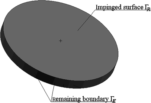
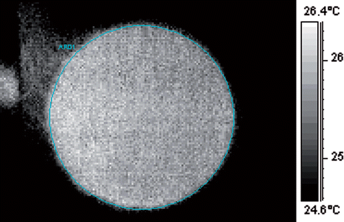
The temperature measurements required by the developed inverse procedure were carried out on the test rig shown in . The experiment involves a single-phase jet impinging a flat cylindrical plate. An electrical heater heats up the compressed air up to 323 K. When constant air parameters are reached, the valve is opened and the air flows through a nozzle and hits the heated sample. The sample, shown in , is a steel cylinder of 60 mm diameter and 5 mm thickness. The properties of the material are supplied by the manufacturer. The transient temperature measurements are taken at the surface opposite to the impinged one by an infrared camera. Every second, five images are taken and the measurements continue until a steady-state temperature field is reached. The most valuable information about the temperature field comes from the initial time period as the temperature variation is large. Therefore, only the data gathered during the first 30 s are taken into account for the inverse analysis. The thermograms recorded before the air impinges the sample show that the initial temperature field is not uniform (). For the inverse procedure, a uniform temperature distribution is assumed and its value is calculated by a software recording data from camera by Equation (1)
(1)
where P is total number of pixels placed on the measured surface. The typical initial temperature difference in the sample is in the range of 1 K. The uncertainty of the measurement comes from the camera, the sample localization and pixel localization, and the total value equals 0.12 K.
3. Developed technique
The retrieval of the HTC requires formulation of the heat flux and boundary temperature problems. The developed technique of retrieving heat flux and temperature resorts to the superposition principle. The boundary of the analysed domain is divided into two parts, denoted as ΓE and ΓR. On ΓE, the boundary conditions (BC) are known and on ΓR, the BC has to be retrieved. Let us consider a case where the heat flux is to be retrieved. After applying the superposition principle, the temperature at any arbitrary point and time moment can be expressed as
(2)
where TE is the temperature field corresponding to the zero flux prescribed on ΓR and the BC on ΓE and the internal heat generation as in the original problem. The second temperature field TR corresponds to homogeneous BCs on ΓE, zero internal heat generation and actual heat flux on boundary ΓR. The superposition principle is applied to express unknown heat flux as a linear combination of known trial functions depending on space and time (3):
(3)
Each trial function is obtained by multiplication of space and time functions, denoted by N and M, respectively. The spatial functions N are local ones, i.e. they are non-zero only at part of the ΓR boundary and are associated with a certain location. The method uses two time trial functions. The first is connected with starting time t = tb = 0 while the second with the ending time t = te. To interpret the approximation coefficients as the values of the searched BC at certain points and time moments, the sum of all trial functions over space and time has to fulfil the condition expressed by Equation (4). Namely, the sum of all trial functions over space and time must be equal to one.
(4)
For each combination of N and M, one forward problem is solved with heat flux qR prescribed on ΓR and homogeneous BC on the ΓE. The resultant temperature field is labelled as , where w is either b or e. Finally, the temperature at any point is given by the following equation:
(5)
To calculate the coefficients of the approximation, the difference between measured and computed temperatures has to be minimized for all sensor locations and time moments. The minimized expression is given by Equation (6).
(6)
where the term
stands for a measured temperature at point ri and time t. The temperature reconstruction procedure is completely analogous. The reconstruction of the spatial distribution of the HTC is pursued in two steps. The first step of the approach involves an evaluation of the two sets of elementary fields: flux part
and temperature part
, for all trial functions. Those fields can be calculated using any of the available analytical or numerical techniques. In the case under consideration, a commercial FEM code MSC.Marc was used. The detailed mathematical derivation can be found in Citation6. It can be shown that the members of both sets can be interpreted as distributions of the smoothed sensitivity coefficients (7) of the temperature with respect to the searched parameters, i.e. boundary temperature and heat flux Citation7.
(7)
The index k stands for the spatial trial function and i for a sensor location. In the second step, the temperature field is expressed as a linear combination of the already obtained fields (4). The searched coefficients qk and Tk are evaluated from the least square fit of the model and the measurements given, respectively, by Equations (6) and (8).
(8)
To retrieve the HTC directly, Equations (6) and (7) are summed up. To enforce constant-in-time HTC, an additional constraint that links the unknown boundary temperature Tj and the heat flux qj is introduced. The constraint is simply a convective boundary condition definition written for unknown temperatures and fluxes for the beginning tb and end te of the time interval (9).
(9)
The use of formula (9) allows us to eliminate unknown heat fluxes from minimized function and replace them by the searched HTC. The objective function is given by (10)
(10)
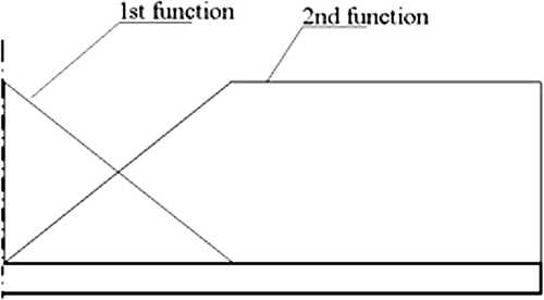
The optimization least square problem is then solved using Levenberg–Marquardt technique, while the elementary temperature fields are evaluated using a commercial FEM code. Thus, the developed technique is capable of dealing with the arbitrary geometry. Furthermore, those fields are calculated only once before entering the iterative loop, which significantly reduce the computation time. The Jacobi (sensitivity) matrix required by the Levenberg–Marquardt procedure is assembled from two constant matrices, i.e. sampled elementary fields, Θk and Ξk. The stability of procedure is further enhanced by high-frequency noise filtration provided by low order, locally-based trial functions. Here, linear and constant trial functions were used ().
4. Results
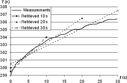
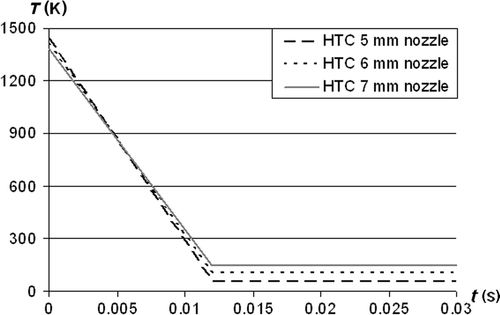
This article presents reconstruction of the spatial distribution of the HTC for three different nozzle diameters d, equal to 5, 6 and 7 mm, respectively. The HTC was reconstructed by a set of two spatial and two time trial functions. The spatial trial functions are presented in . The first function is associated with the stagnation point and its purpose is to reconstruct the maximal value of the HTC. As the expected spatial variation of the HTC in the outer zone of the impinged surface is small, the second trial function associated with r = 0.012 m is constant. To realize the assumption of constant-in-time HTC, both temperature and heat flux must vary in time. Therefore, both time trial functions are linear. One will retrieve the first value at the beginning of the time interval and the second at the end of the interval. In the case under consideration, different lengths of the interval were tested. On the one hand, the shorter the interval, the lesser is the information provided by measurements. On the other hand, a longer interval means a worst fitting of the function into the nonlinear curve (). The tested value of te was between 3 and 30 s. This fact has one more important implication, i.e. the initial temperature which is known is also retrieved. If this was not the case, the temperatures at the end of the interval would have been highly overpredicted.
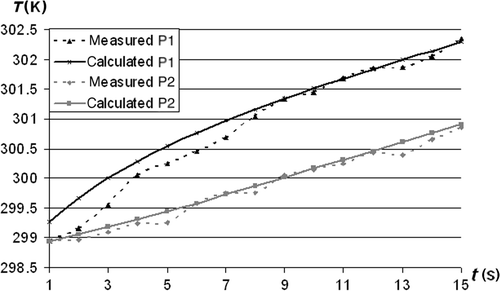
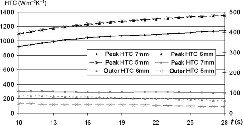
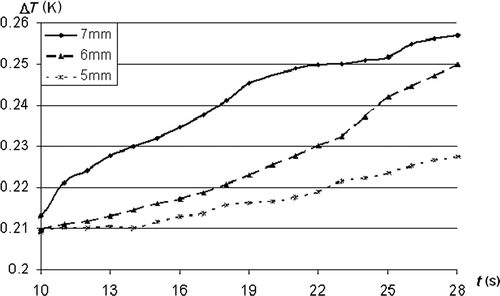
The retrieved HTC for all three nozzle diameters are presented in . For all three diameters, the maximal value of the HTC is in the stagnation point. Then its value decreases rapidly until the minimal value is reached. The minimal value equals 5–10% of the peak one. With the increase of the diameter, the peak value of the HTC is reduced while the outer one slightly increases. The accuracy of the retrieval is verified by the so-called check run. In the check run on the retrieval surface the reconstructed constant-in-time HTC is prescribed. The temperature field obtained from this calculation is then compared with the measured one. The results are shown in . The comparison was done for two points for each nozzle diameter. Point P1 is located in the centre of the impinged surface – i.e. in the stagnation point while the second point P2 lies on the same surface at a distance of 0.012 m from the impingement point. The results show good agreement between compared temperatures, especially in the case of point P2. In the case of the point P1, the retrieval is not so good for the first few seconds of the considered time interval. It is due to the non-uniform temperature field in the object while the retrieval procedure assumes one temperature value in the whole heated sample. The average temperature difference for the whole time interval and all considered points lie between 0.2 and 0.3 K. The influence of the length of the time interval taken into account on the reconstructed HTC is shown in . The peak values are marked on the main axis while the outer ones on the secondary axis. For all nozzle diameters, the peak value of the HTC increases while the outer one decreases with the increase of the considered time. Therefore, the average temperature differences were compared to find the time at which the retrieval is the best. Unfortunately, this difference increases with the increase of the time interval (). The fact would indicate that a very small interval gives the best results. However, for time intervals smaller than 10 s, results are often unstable. Therefore an additional criterion needs to be found or a considered interval needs to be divided into a small number of subintervals for which the HTC will be reconstructed separately.
5. Conclusions
The presented technique is a general purpose spatial HTC distribution reconstruct method for heat exchange problems. Its universality comes from the fact that it is independent of the physical phenomenon occuring in the fluid as only solid heat conduction problems are solved. In the case at hand, the proposed method was used to retrieve HTC for the submerged air jet heating problem. For all three nozzles, good agreement between numerical simulation and measurements was achieved. The central assumption of the proposed technique is the linearity of the underlying direct problem, which allows us to resort to the superposition principle. As a result, the approach requires only one solution of the direct problem for every combination of time- and space-trial functions. Therefore the method is very fast. The byproducts of the solved direct heat conduction problems are the sensitivity coefficients which are very helpful in the experiment planning.
The next important feature of this approach is the fact that the retrieved function is approximated by a linear combination of locally based trial functions. These functions are analogous to the shape functions used in FEM but defined on a much coarser mesh.
The inverse problems are ill-posed and this means that the errors in the input data are amplified during the solution procedure. This may lead to the instability in the solution. This was experienced here during an attempt to capture the HTC behaviour in the turbulent transition zone. Simple constant and linear trial functions were used in the developed method to filter out the high-frequency errors and decrease the influence of the ill-conditioning on the solution. Nevertheless, care should be exercised when deciding about the number retrieved parameters. The attempt to estimate too many may significantly reduce the stability. Therefore, the best possible solution is a matter of compromise between the number of retrieved parameters and the robustness of the algorithm.
The main limitation of the proposed method is an arbitrary selection of the location of nodes of trial functions used to approximate the retrieved BC. To minimize the influence of this issue, any available information concerning the shape of the retrieved function should be utilized when locating the spatial functions. If the retrieved function assumes a maximum at a given point, a node of the trial function should be located at this very point. It is very important to notice that the inverse solution depends on the time interval. Therefore, further investigation in that direction has to be made. One possibility is to divide the whole interval into several sub-intervals. That would improve the quality of the temperature and flux approximation. Also, the influence of the initial condition error would be present only in the first step.
References
- O’Donovan, TS, and Murray, DB, 2007. Jet impingement heat transfer: Part I. Mean and root-mean-square heat transfer and velocity distributions, Int. J. Heat Mass Transfer 50 (2007), pp. 3291–3301.
- Stevens, J, and Webb, BW, 1991. Local heat transfer coefficients under an axisymmetric, single-phase liquid jet, J. Heat Transfer 113 (1991), pp. 71–78.
- Xu, F, and Gadala, MS, 2006. Heat transfer behavior in the impingement zone under circular water jet, Int. J. Heat Mass Transfer 49 (2006), pp. 3785–3799.
- Anderson, BA, and Paul Singh, R, 2006. Effective heat transfer coefficient measurement during air impingement thawing using an inverse method, Int. J. Refrig. 29 (2006), pp. 281–293.
- Białecki, RA, Divo, E, Kassab, AJ, and Ait Maalem Lahcen, R, 2003. Explicit calculation of smoothed sensitivity coefficients for linear problems, Int. J. Numer. Methods Eng. 57 (2003), pp. 143–167.
- Ryfa, A, Białecki, RA, Facchini, B, and Tarchi, L, 2009. Application of the inverse analysis for boundary condition retrieval, Inverse Probl. Sci. Eng. 17 (2009), pp. 829–853.
- Kurpisz, K, and Nowak, AJ, 1995. Inverse Thermal Problems. Southampton: Computational Mechanics Publications; 1995.

