Abstract
This article deals with the behaviour of acoustic cavities in the mid-high-frequency range. An energy method called simplified energy method (MES) has already been proposed to predict energy levels in acoustic cavities. The direct MES provides energy density repartitions from the knowledge of input power and power dissipated at the boundaries. In this article we propose that the MES can be used to solve inverse problems. More precisely, the dissipated energy at the acoustic domain boundaries are retrieved from the knowledge of energy densities. The inverse MES formulation is first defined and a simple acoustic cavity test case is analysed, displaying the efficiency of the proposed method. The nature and the quality of input data as well as other parameters will be considered.
1. Introduction
This article deals with inverse acoustic problems that may be encountered in industrial contexts. We give an example of noise in an aircraft cabin – the source of the noise can be determined by in-flight measurements performed in the cabin. Many numerical methods allow us to estimate the noise in acoustic cavities in low, medium or high frequencies. In some acoustic studies, the location and the characteristics of the sources are unknown. The models used in direct problems are then inverted, where the sources are identified from the measurements of their effects. These effects correspond generally to acoustic pressures obtained by microphones.
Two possible issues arise when considering inverse acoustic problems. The first issue is low-frequency problems, which are mostly treated through inverse FEM, BEM or FRF methods since these techniques are well adapted to this frequency range Citation1–10. Indeed, the ‘low-frequency domain’ is a frequency range where the modal overlap is low and modal information clearly appears; therefore, in this frequency range, structures do not require fine meshing and FEM or BEM calculation costs are not too high.
For higher frequency ranges, several approaches can be used. Some techniques are based on low-frequency methods such as BEM or FEM. However, these techniques lead to very fine meshing and are quite costly. For example, an FEM or BEM calculation on a complex structure (aircraft, car, etc.) can take several hours or days whereas energy methods (statistical energy analysis (SEA) or simplified energy method (MES)) would take seconds or minutes, since this kind of method does not require fine meshes. For inverse problems, the difficulty is due to acquiring numerous data by measurements. We could also consider defining the input force so that the measured set of inputs verify the equilibrium equations given either in a continuous or discretized format. For instance, in Citation2,Citation8,Citation11, the authors developed an interesting strategy named the RIFF method for identifying vibration sources. In this method, the equations of motion are discretized through a finite difference scheme and the force of distribution is computed from a set of measured displacements on the structure. Regularization is achieved through a spatial window and a wavenumber filter. Acoustic holography methods are also used Citation11--13 and provide accurate results. More precisely, nearfield acoustical holography (NAH) methods are often used for identifying source velocity fields. These methods were first introduced by Williams et al. Citation14,Citation15 and have been applied to simple geometries Citation16, pp. 89--114, 149--189, 235--249]. More recently, some authors introduced hybrid methods based on acoustical holography Citation17,Citation18, however, problems of discontinuities remain at boundaries and the cost of these kinds of techniques can be quite high. In this article, we consider an inverse energy method which allows us to detect the main acoustic sources of a system very quickly. This approach allows us to use very few measurements and produce global results; for example, in the case of in-flight measurements for detecting acoustic sources in aircrafts, where the cost of flights restricts the number of measurements. Here we need a fast method, even if the results are not as accurate as holography methods.
Energy methods are often good alternatives in the high and medium frequency range when numerical methods such as finite or boundary element-based formulations are computationally expensive. Among these energy methods, the most recognized is SEA Citation19, which gives the mechanical energy of complex build-up structures.
Many energy methods have been based on SEA, with the aim of enhancing its robustness and predictability. Nefske and Sung Citation20 extended SEA densities to a local energy formulation, which predicts the space spread of energy density within subsystems. Many authors have improved this method Citation21,Citation22 to the MES.
The MES has been applied to various domains: beams Citation21,Citation23, membranes and plates Citation21,Citation24--26 and acoustical radiation Citation27,Citation23, and some authors have also developed transient approaches Citation28--30.
2. Overview of the direct MES
2.1. Assumptions
The MES is based on the description of two local energy quantities. The first is the total energy density , defined as the sum of the potential and kinetic energy densities. The second energy variable
is the energy flow. We look for a relationship between these quantities and the acoustic sources applied on the cavity. Thus, the mathematical formulation involves determining a function 𝒫 linking the energy quantities
and the input power flow πinp:
(1)
We now describe the steps leading to the direct MES formulation. Energy equations will be explained and discretized in order to provide a matrix formulation of the problem. First, we express the energy balance of the system in the following form:
(2)
where
is the gradient operator, πdiss is the dissipated power density and πinp is the input power density. The damping model of the MES method is similar to the SEA damping model, and has already been discussed in the literature Citation19 and can be expressed as follows:
(3)
where η is the damping loss factor and ω the circular frequency.
The propagating waves considered in the MES formulation are constructed from partial energy quantities corresponding to direct and reverberated fields. The direct field comes from the input power source, and the reverberated field comes from reflections of the direct field on the boundaries. According to the considered fields, W and are both quadratic variables, and the superposition principle (i.e. the total field is the sum of the direct and reverberated fields) can be applied:
(4)
where £i are N quadratic variables corresponding to the global or partial energies associated to the wave fields (W, Wi) or
. This assumption is often used in statistical phenomenon in physics, and we can consider such an assumption in room acoustics, electromagnetism, etc. In what follows, an intrinsic energy law will be used. In fact, this superposition principle is valid even if a term, due to the phase, is neglected. If we consider two waves, denoted by u1 and u2, we can write the following equation:
(5)
These terms can be neglected because the quantities considered in MES are frequency average quantities (see MES references Citation25,Citation31,Citation32). Therefore, we can write
(6)
where
, where Δf is the considered frequency range for the frequency average. This means that the MES does not take into account the modal information (linked to the phase of the waves).
In the following, an intrinsic energy law is used, which is often introduced to define the wave velocity c (see, e.g. paper Citation31):
(7)
2.2. Direct formulation
In this section, we derive the MES formulation in an nD space. In this article we consider the 3D case, with 2D plates studied in future work. The two cases are considered separately since the discretization of the energy equations is different in two and three dimensions, along with other issues.
By considering the symmetrical wave field and Equations (7) () and (2) (
), the MES approach Citation33 leads to the following relation:
(8)
which can also be written using Equation (7):
(9)
Finally, Equation (9) can be rewritten by considering only the W field:
(10)
Equation (10) is called the local energy equation for symmetrical waves.
This equation was first proposed by Kuttruff Citation34. This is known as the radiosity method, and it is this approach that we consider here. Further contributions and details can be found in Citation35.
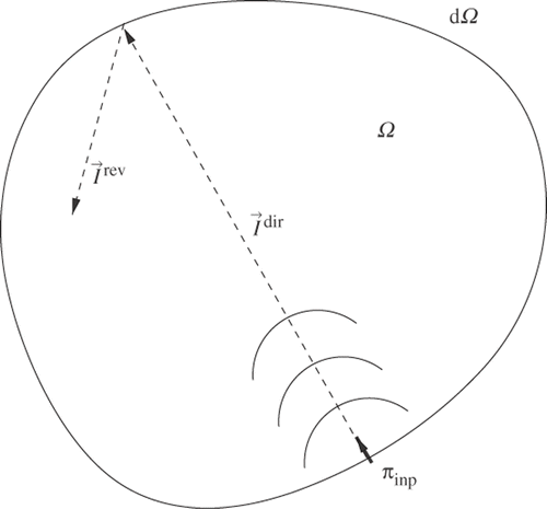
We also consider symmetrical waves with energy variables defined as the superposition of direct and reverberated fields, which can be added to obtain the total field, shown in Equation (4). A representation of these fields is given in , where is the direct field and
is the reverberated field; note that only the intensity field is drawn.
The elementary solutions of equations derived in (8)--(10) representing the energy density and active intensity are denoted as G and and given by
(11)
where γ0 is the solid angle of the considered space (2 in one-dimension, 2π in two-dimensions and 2π in three-dimensions), r is the observed radius and
is the radial vector. We recall that ω is the circular frequency and η is the damping factor. Hence, using a superposition principle, the energy solution can be expressed using the contributions of the primary source ρ (direct field) and fictitious sources σ. The fictitious sources are energy unknown parameters representing the contribution of the reverberant field. Therefore, we have
(12)
and the intensity field can be described by a similar expression:
(13)
For 3D problems, we only consider ρ and σ corresponding to sources situated on the boundaries. We do not consider sources situated in the cavity, since we want to find the input power flow on the boundaries of an acoustic cavity.
3. Formulation of an inverse energy problem – IMES
We propose, in the context of the inverse problem, the discretizing direct MES formulation, where the resulting matrix equation will be inverted.
We define a matrix T that is the N × N geometric interaction matrix between N cavity facets, with entries given by the following formula, obtained by considering and the distance rij between two facets:
(14)
where di(θi) is a directivity term. We will explained in the following sections how we choose this directivity term, which depends on the characteristics of the source. In acoustic problems, when the directivity is not well known, a value of
is often assumed. The following equations are valuable for any value of
, hence we will replace it by its value only for the numerical application.
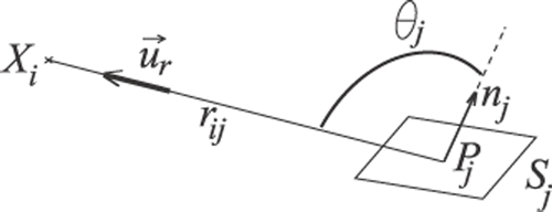
Next, referring to , we define two N × m matrices namely YW and YI matching the geometric interaction between N elements and m measurement points. These matrices are determined respectively, for W and I, by the following equations:
(15)
(16)
where d(θ) is a directivity term which depends on the re-emission angle θ.
The point Xi corresponds to the measurements of the ith sensor.
By considering and , the power balance on one element i can be expressed as follows:
(17)
We also define matrices M and B as follows:
(18)
(19)
where
(20)
is a diagonal matrix corresponding to the absorption co-efficients of each facet and IN, the identity matrix. The absorption co-efficient indicates how much of the sound is absorbed in the actual material. It can be expressed as
, where Ia is the sound intensity absorbed and Ic is the incident sound intensity. Of course, the absorption co-efficients depend on the considered materials. It should also depend on the incidence angle, which is not taken into account in this article.
Equation (17) leads to the following relationship:
(21)
Thus, the relationship between the vectors σ and ρ is given by
(22)
Considering Equations (12), (13) and (22), W and I can be obtained from the following equations:
(23)
(24)
where SW and SI are defined by
(25)
(26)
Finally, we can define the relationship between (W, I) and ρ corresponding to the linear operator ℱ:
(27)
The inverse MES formulation aims to invert the operator ℱ proposed in Equation (27). Sources will be detected by measurements taken in the acoustic cavity. Note that the matrix
(28)
may not be square.
As the number of measurements may not be equal to the number of sources, the problem is not always directly invertible. Therefore, we look for an operator 𝒢, given below, that gives σ and ρ as functions of W and :
(29)
We introduce
(30)
where f og(x) = f(g(x)), since the problem leads to the minimization of the quantity R(𝒳).
The MES Equations (12) and (13) are discretized to obtain the following matrix formulation:
(31)
where m is the number of the measurements and q is the number of the boundary sources.
We recall that we only deal with boundary sources because our study is concerned with the detection of external excitations in aircraft cabins (or other industries, such as the automotive, etc.). Therefore, as we only consider boundary sources, the problem can be inverted using the following pseudo inverse matrix:
(32)
where S is a matrix collecting SW and SI, given in Equations (25) and (26) and already defined in (28). Matrix S can be quite well-conditioned, but is often ill-conditioned, which will affect the results. In the next sections, we will see the influence of the inversion of S on the results.
4. Numerical results
4.1. 1 boundary source
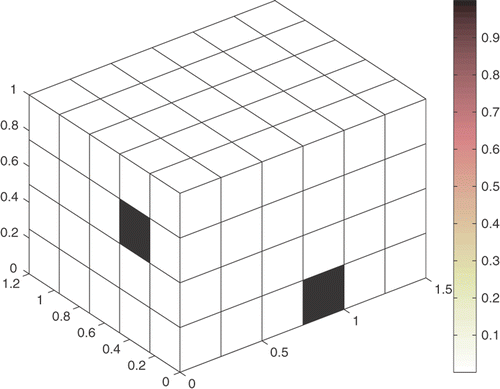
In this section, we consider a fluid cavity with absorbent boundaries. gives the cavity dimensions and the fluid characteristics. This cavity is excited by a boundary source located at the coordinates (0, 0.39, 0.66), and the input power is equal to 1 W m−2.
Table 1. Cavity dimensions and fluid characteristics.
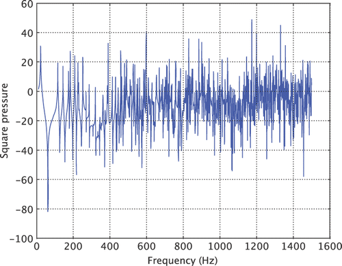
In this numerical example, we consider the high-frequency phenomena, and produce MES/IMES simulations. The results presented in this section are computed for frequencies around 1000 Hz, which means the modal overlap is quite high and the use of energy variables is essential. shows the frequency response of the squared pressure at a point in the acoustic cavity, considering a pressure excitation on a boundary, the dimensions of the cavity matching the data given in . The modal density becomes to be particularly high from 400 Hz. At 1000 Hz, one can consider that the modal overlap is sufficiently high and the MES assumption is valid.
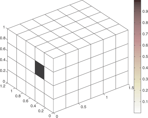
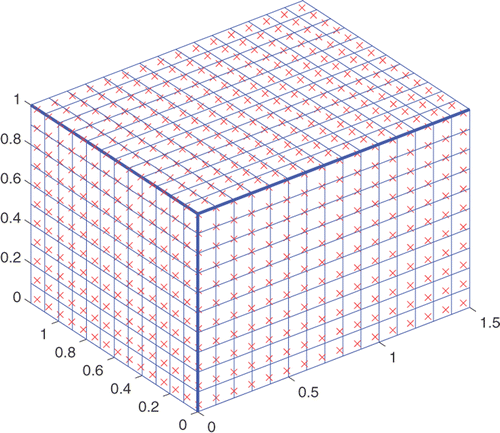
Therefore, W, in the MES formulation, will be determined using N = m = 148. We recall that N is the number of facets obtained by cavity discretization, and m is the number of ‘numerical measurements’. Results found for the MES/IMES simulation are presented in .
This result shows the inversion of (STS) is validated since we find a good location and level of the boundary source.
Now we compare the MES results with an FEM/IMES simulation. In fact, IMES calculations are processed using W, computed by finite element software. The same FEM model (cavity and characteristics) is processed with both the same excitation, 1 W m−2, and number of elements N (the FEM mesh is made of 9296 elements and we can observe 270 modes between 707 and 1414 Hz). In this simulation, the pressure applied on the point of the cavity boundary is given by
(33)
Now, we introduce to quantify the efficiency of the method. The parameter ξ = 1 corresponds to a square matrix to invert, whereas ξ < 1 corresponds to a greater number of elements N compared to the number of measurements m. Results produced for fc = 1000 Hz, and for different values of ξ, are given in . The m measurements are located in front of the boundaries of the box, as shown in .
Figure 6. FEM/IMES simulations for (a) ξ = 0.63, (b) ξ = 1, (c) ξ = 1.59, (d) ξ = 1.93, (e) ξ = 2 and (f) ξ = 2.32.
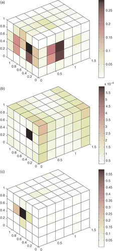
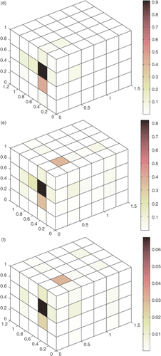
We note that the source needs a value of ξ = 1 to be correctly localized and good identification of the source in the FEM/IMES simulation is obtained for ξ = 1.93.
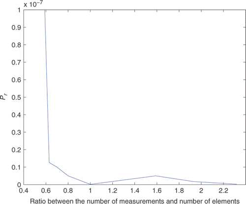
By varying ξ, we can represent the identification evolution by introducing the precision term Pr as follows:
(34)
where ρi is the ith component of the input power vector and
is the ith component of the exact input power vector. The evolution of this precision term according to the variation of ξ is illustrated in .
It appears that the value of Pr increases greatly for ξ ≤ 1 and for ξ > 1 we notice that the curve is stabilized with Pr ≤ 0.1 × 10⁻⁷, which means that the inverse MES is validated with good accuracy in the case of one boundary source for fc = 1000 Hz and ξ ≥ 1.
We observe that good results can be obtained for values of ξ close to 2. For higher or lower values of ξ, the correct level of the source is not found. This lack of precision concerning the level of the source could be due to the lack of knowledge of the directivity of the source. Indeed, we assume in this article that a directivity , which is not always validated, since the directivity depends on the kind of source – and we know nothing about it. We note that the correct directivity cannot be found through MES, and additional research is required in order to be able to take correct directivities into account through hybrid methods Citation31.
4.2. 2 boundary sources
In this example we consider the same fluid cavity with the same dimensions and fluid characteristics. This cavity is excited by 2 boundary sources (q = 2) located at (0, 0.39, 0.66) and (0.8, 0, 0.2) with the same input power of 1 W m−2. Results found for the MES/IMES simulation with N = m = 148 are presented in .
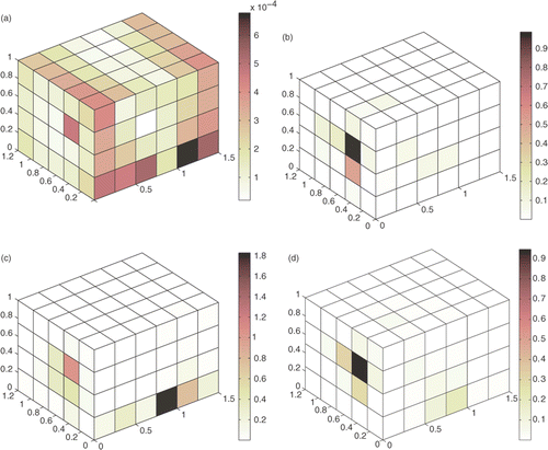
Results are very good for the level and location for both sources, which confirms that the inversion of (STS) is validated. For the FEM/IMES simulation, the same FEM model (cavity and characteristics) is processed with the same excitation for 1 W m−2 and the same number of elements N (). In this simulation, the pressure coming from the boundary excitations is calculated using Equation (33). Results obtained using fc = 1000 Hz, and for different values of ξ, are presented in .
Table 2. Noise sensitivity: introducing random error (ε).
Table 3. Characteristics of the model.
We note that in the case of a cavity excited by two sources localized in two different boundary facets, and for varying ξ, only one source is identified with a level near to the input power value (1 W m−2). More precisely, the first source is identified for ξ = 1.72 and ξ = 4.25 and the second one is localized for ξ = 4 with an input power value equal to 1.8 W m−2.
4.3. Influence of noisy measurements
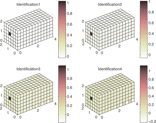
In this section, we consider the robustness of the inverse method. In order to check the sensitivity of the method, we produce an MES/IMES simulation introducing noise into the numerical measurements. shows the results of this simulation considering different levels of noise cases – i.e. introducing a random error ε on the data – given in , and the characteristics of the box are recalled in . Notice that the inverted system is square; moreover, the numerical measurements are ‘exact’ since they come from a direct MES computation. The results should then be perfect if no noise is introduced. These results show that the method is quite robust since the input source is well located, even if the results are obtained with a higher level of noise in cases 3 and 4.
5. Conclusion
In this article we have investigated the performance of the simplified energy method (MES) to identify sources from measurements processed in acoustic cavities. In Section 2, the MES formulation and assumptions are detailed. In Section 3, the inverse formulation is given which involves identifying sources through data energy recovered from the cavity. In Section 4, the MES was validated and compared with FEM/IMES simulations taking numerical data produced by FEM software in the range of medium and high frequencies. The performance of this method is validated in the case of one boundary source. Research is in progress to validate the method for other excitation cases and to take into account the ‘correct’ directivity of the sources, which involves determining the level of the sources. It also should be interesting to validate the method experimentally, which would give rise to difficulties linked to the measurements.
References
- Augusztinovicz, F, and Tournour, M, 2000. "Reconstruction of source strength distribution by inversing the boundary element method". In: von Estorff, O., ed. Boundary Elements in Acoustics: Advances and Applications, Advances in Boundary Elements Vol. 9. Southampton: WIT Press; 2000, Chap. 8.
- Djamaa, MC, Ouelaa, N, Pezerat, C, and Guyader, JL, 2007. Reconstruction of a distributed force applied on a thin cylindrical shell by an inverse method and spatial filtering, J. Sound Vibration 301 (2007), pp. 560–575.
- Hamdi, MA, Omrani, A, Ouisse, X, Mein, M, and Sauvage, O, Presentation of a new inverse boundary element method for the determination of optimal spectral characteristics of complex noise sources, Euronoise Conference, Napoli, 2003.
- Hamdi, MA, Defosse, H, and Gagliardini, L, 2002. "Hybrid inverse boundary element method for the determination of the optimal spectral characteristics of complex radiating noise sources". In: Internoise 2002. MI, USA: Dearborn; 2002.
- Ji, C-C, and Liang, C, 2000. A study on an estimation method for applied force on the rod, Comput. Methods Appl. Mech. Eng. 190 (11--12) (2000), pp. 1209–1220.
- Liu, J-J, Ma, C-K, Kung, I-C, and Lin, D-C, 2000. Input force estimation of a cantilever plate by using a system identification technique, Comput. Methods Appl. Mech. Eng. 190 (11--12) (2000), pp. 1309–1322.
- Ma, CK, Chang, JM, and Lin, DC, 2003. Input force estimation of beam structures by an inverse method, J. Sound Vibration 259 (2) (2003), pp. 387–407.
- Pezerat, C, and Guyader, JL, 2000. Identification of vibration sources, Appl. Acoust. 63 (2000), pp. 309–324.
- Schummacher, A, and Hansen, PC, 2001. "Sound source reconstruction using inverse BEM". In: Internoise2001. The Netherlands: The Hague; 2001.
- Visser, R, 2002. "Inverse source identification based on acoustic particle velocity measurements". In: Internoise2002. MI, USA: Dearborn; 2002.
- Pezerat, C, Leclere, Q, Totaro, N, and Pachebat, M, 2009. Identification of vibration excitations from acoustic measurements using near field acoustic holography and the force analysis technique, J. Sound Vibration 326 (2009), pp. 540–556.
- Bai, MR, 1992. Application of BEM-based acoustic holography to radiation analysis of sound sources with arbitrarily shaped geometries, J. Acoust. Soc. Am. 92 (1992), pp. 533–549.
- Schummacher, A, Hald, J, and Saemann, E-U, 1999. A comparison of inverse boundary element method and near-field acoustical holography applied to sound radiation from a tyre, Sixth International Congress on Sound and Vibration, Copenhagen (1999).
- Williams, EG, 1997. The nearfield acoustical holography (NAH) experimental method applied to vibration and radiation in light and heavy fluids, Comput. Struct. 65 (3) (1997), pp. 323–335.
- Williams, EG, Maynard, JD, and Skudrzyk, E, 1980. Sound source reconstructions using a microphone array, J. Acoust. Soc. Am. 68 (1980), pp. 340–344.
- Williams, EG, 1999. Fourier Acoustics: Sound Radiation and Nearfield Acoustical Holography. London: Academic Press; 1999.
- Wu, SF, 2004. Hybrid nearfield acoustical holography, J. Acoust. Soc. Am. 115 (2004), pp. 207–217.
- Zhao, X, and Wu, SF, 2004. Reconstruction of vibro-acoustic fields using hybrid nearfield acoustic holography, J. Sound Vibration 282 (3) (2004), pp. 1183–1199.
- Lyon, RH, 1975. Statistical Energy Analysis of Dynamical Systems: Theory and Application. Cambridge, MA: MIT Press; 1975.
- Nefske, D, and Sung, S, 1989. Power flow finite element analysis of dynamic systems: Basic theory and application to beams, J. Vibration, Acoust. Stress Reliability 111 (1989), pp. 94–106.
- Lase, Y, Ichchou, M, and Jezequel, L, 1996. Energy analysis of bars and beams: Theoretical formulations, J. Sound Vibration 192 (1996), pp. 281–305.
- Wohlever, J, and Bernhard, R, 1992. Mechanical energy flow models of rods and beams, J. Sound Vibration 153 (1992), pp. 1–19.
- Wang, A, Vlahopoulos, N, and Wu, K, 2004. Development of an energy boundary element formulation for computing high-frequency sound radiation from incoherent intensity boundary conditions, J. Sound Vibration 278 (1--2) (2004), pp. 413–436.
- Bouthier, OM, and Bernhard, RJ, 1995. Simple models of energy flow in vibrating membranes, J. Sound Vibration 182 (1) (1995), pp. 129–147.
- Hardy, P, Ichchou, M, Jezequel, L, and Trentin, D, 2009. A hybrid local energy formulation for plates mid-frequency flexural vibrations, Eur. J. Mech. A: Solids 28 (1) (2009), pp. 121–130.
- Houillon, L, Ichchou, M, and Jézéquel, L, 2005. Wave motion in thin-walled structures, J. Sound Vibration 281 (3--5) (2005), pp. 483–507.
- Cotoni, V, Le Bot, A, and Jezequel, L, 2002. High frequency radiation of l-shaped plates by a local energy flow approach, J. Sound Vibration 250 (3) (2002), pp. 431–444.
- Ichchou, MN, Le Bot, A, and Jézéquel, L, 2001. A transient local energy approach as an alternative to transient sea: Wave and telegraph equations, J. Sound Vibration 246 (5) (2001), pp. 829–840.
- Sui, F, and Ichchou, MN, 2004. Prediction of time-varying vibroacoustic energy using a new energy approach, J. Vib. Acoust. 126 (2) (2004), pp. 184–189.
- Sui, FS, Ichchou, MN, and Jézéquel, L, 2002. Prediction of vibroacoustics energy using a discretized transient local energy approach and comparison with TSEA, J. Sound Vibration 251 (1) (2002), pp. 163–180.
- Besset, S, Ichchou, MN, and Jézéquel, L, 2010. A coupled BEM and energy flow method for mid-high-frequency internal acoustic, J. Comput. Acoust. 18 (1) (2010), pp. 69–85.
- Hardy, P, Jezequel, L, and Ichchou, M, 2002. Absorption co-efficient and energy flow path identification by means of inverse local energy method, J. Acoust. Soc. Am. 112 (5) (2002), pp. 2320–2320.
- Ichchou, M, and Jezequel, L, 1996. Comments on simple models of the energy flow in vibrating membranes and transversely vibrating plates, J. Sound Vibration 195 (1996), pp. 679–685.
- Kuttruff, H, 1997. Energetic sound propagation in rooms, Acoustica Acta Acoustica 83 (1997), pp. 622–628.
- Carroll, MM, and Chien, CF, 1977. Decay of reverberant sound in a spherical enclosure, J. Acoust. Soc. Am. 62 (6) (1977), pp. 1442–1446.
