Abstract
We transpose an optimal control technique to the image segmentation problem. The idea is to consider image segmentation as a parameter estimation problem. The parameter to estimate is the colour of the pixels of the image. We use the adaptive parameterization technique which builds iteratively an optimal representation of the parameter into uniform regions that form a partition of the domain, hence corresponding to a segmentation of the image. We minimize an error function during the iterations, and the partition of the image into regions is optimally driven by the gradient of this error. The resulting segmentation algorithm inherits desirable properties from its optimal control origin: soundness, robustness and flexibility.
1. Introduction
The segmentation of an image is usually defined as the identification of subsets of points with similar image properties, such as the brightness or the colour (local properties), or the texture (global property). Image segmentation is usually subdivided into two main classes: edge detection approaches that follow the variations of the image properties and region-based approaches that follow directly the image properties (see, e.g. Citation1–9).
The idea of introducing an optimization process to guide a segmentation algorithm has already been investigated. Koepfler et al. Citation10 introduce an energy to minimize and develop a ‘region merging’ algorithm for grey level and texture segmentation. The energy method in image segmentation is introduced by Geman and Geman Citation11. Later a large variety of energy methods was developed. A formulation of the image segmentation as a piecewise modelling problem combined with an energy method is given in Citation12. Uchiyama and Arbib Citation13 incorporate optimization in a merge–split, region-based image segmentation method; their algorithm converges to a local optimum solution of clustering colour space based on the least sum of squares criterion.
The connection between inverse problems and image segmentation has already been noticed (see, e.g. Citation14). Furthermore, an approach close to the one we are developing can be found in Citation15, where the segmentation is built through a piecewise least-squares approximation of a function related to image intensity. But unlike ours, the refinement of the segmentation is uniform and the refinements are selected from a fixed predefined set.
The optimal adaptive segmentation algorithm presented in this article is also based on an optimization process. At each step, the refinement is optimally obtained from the gradient of the objective function to be minimized. The resulting regions are not geometrically constrained, as they are not required to be connected. Noticeably, all the steps of the algorithm are meaningful, since the algorithm progressively goes from the coarsest segmentation to the finest one, i.e. from a single monochrome region up to the complete reconstruction of the original image with one region per distinct colour.
This leads to some kind of segmentation on demand: since the n-th iteration provides the segmentation into n regions, the algorithm can segment the image into any given number of zones, with each zone having an optimal colour with respect to the overall error from the original image. Moreover, since each step of the algorithm selects a single region and splits it into two parts, the adaptive segmentation algorithm can be used to interactively refine the segmentation of an image.
This adaptive approach was initially developed for the inverse problem of parameter estimation: given a forward modelling map, the multidimensional adaptive parameterization algorithm Citation16 solves the inverse problem of estimating a multidimensional distributed parameter from measured data. For instance, colours are defined by their three Red/Green/Blue (RGB) components, thus colour images can be seen as three-dimensional distributed parameters. Hence, when the parameter to be identified is a colour image and the forward map to be inverted is the identity, this optimal control technique provides naturally an image segmentation algorithm that refines regions guided by the misfit between the original and segmented image.
As illustrated in Citation16, brute force application of this algorithm to image segmentation gives interesting results. But the original handling of the multidimensional aspect of the parameter proposed was rather naive. So this aspect is revisited, developed and enriched in this article, specifically for the case of image segmentation: beside vector segmentation algorithms, where each region is associated with one colour, we also introduce multiscalar segmentation algorithms, where each colour channel has its own segmentation. When transposed back to the general case of nonlinear inverse problem, the new algorithms are also expected to provide more flexibility.
Notice that although adaptive parameterization uses the so-called cuttings that can be considered as defining edges, this ‘edge detection’ aspect is just an auxiliary step to define the partitioning of the set of pixels into regions. Thus, we still classify our image segmentation algorithm in the region-based techniques.
This article is organized as follows. In Section 2, we explain the similarity between parameter estimation and image segmentation and we illustrate the usage of adaptive parameterization to segment a simple image. In Section 3, we give some mathematical foundations and the description of the optimal adaptive vector and multiscalar segmentation algorithms. In Section 4, we use the previous algorithms to segment a colour image, and compare their relative performances.
2. From parameter estimation to image segmentation
2.1. Parameter estimation
Parameter estimation is a class of inverse problems, where a simulation model has been constructed but some of its parameters are not precisely known. It consists of trying to recover these parameters from a collection of input–output experimental data.
A classical approach to this inverse problem is to formulate it as the minimization of an objective function defined as a least-squares misfit between experimental output data and the corresponding model-generated quantities:
(1)
where c denotes the unknown parameter, d the data and ℱ is an operator corresponding to the model describing the cause-to-effect link from c to d.
For a large class of inverse problems, the unknown parameters are space-dependent coefficients in a system of partial differential equations modelling a physical problem. Due to the difficulty and high cost of experimental measurements, the available data are often too scarce to allow for the determination of the parameter value in each cell of the computational grid.
Therefore, one has to reduce the number of unknown parameters: a convenient way is to search for unknown distributed parameters as piecewise constant functions, as an approximation to the necessarily more complex but unattainable reality.
Then parameter estimation amounts to identify both the spatial distribution of regions of constant value and the associated parameter values. The result of the parameter estimation is then a partition of the spatial domain into regions together with one (possibly multi-dimensional) parameter value per region.
2.2. Image segmentation
Let us now consider the case where the data d is an image, made of a set of pixels (picture elements). Each pixel is the association of a cell xi with its corresponding colour value di:
(2)
We shall denote by D the domain of the image, i.e. the set of all its cells xi:
(3)
2.2.1. Vector segmentation
A vector segmentation of d consists in replacing it by an image c = {(xi, ci), i ∈ I } (where c stands for ‘computed’) with the same domain such that:
| • | c has a uniform colour sR (where s stands for ‘segmented’) on each region R of a partition 𝒫 of its domain D:
| ||||
| • | the image c bears some resemblance to the original image d. | ||||
Here we have chosen to ensure the resemblance between the segmented and original images c and d by requiring that their least-squares misfit is made ‘small’, or, in more mathematical terms:
(5)
under the constraint that the number of regions of 𝒫 is ‘small compared to the number of pixels of d ’.
Without the constraint on the number of regions, a trivial exact solution to problem (5) is the segmentation made of one region for each pixel, with the region colour being the colour of its unique pixel. However, this trivial exact solution is not satisfactory, since it is not adequate to the segmentation idea. It corresponds to the ultimate level of over-segmentation.
This approach can be seen as a top-down region-based one since we keep refining the regions: at each iteration, the algorithm detects a discontinuity in one region colour sR which give a smaller value to J(c), so the algorithm can also be seen as defining an implicit edge detection.
The result of a vector segmentation of an image d is hence a partition 𝒫 of its domain D into regions, together with the data of one colour value sj per region. In such a segmentation, all colour components use the same partition.
2.2.2. Multiscalar segmentation
Another way to obtain an image with piecewise constant colours is to find a different partition for each colour component. We have chosen to use the RGB basis, but any other representation could be used as well. So we define a multiscalar segmentation of d as the operation which replaces d by an image c = {(xi, ci), i ∈ I } such that:
| • | for each k = R, G, B, the component ck of c has a uniform intensity | ||||
| • | the image c bears some resemblance to the original image d, | ||||
The approach proposed here can produce both vector and multiscalar segmentations, and controls the segmentation level.
2.3. Image segmentation considered as a particular parameter estimation problem
Similarities between the two previous sections show that vector segmentation of images can be seen as a parameter estimation problem, where the forward model ℱ reduces to the identity map (compare (1) and (5)) and complete data are available (since the exact colour is known for each cell).
The parameter estimation problem, because of the nonlinearity of the governing model ℱ and the scarcity of data, is often ill-posed and difficult to solve. In contrast, one can expect that the parameter estimation algorithms will work efficiently for vector segmentation, because of the good properties of the associated forward map ℱ and data. So in this article we adapt the multidimensional refinement indicators algorithm Citation16 to the specificities of vector segmentation, and extend it to the determination of multiscalar segmentations.
Remark 1
The segmentation of an image can also be attempted according to other properties than colour, for example texture. The approach developed in this article can be adapted to these situations by a proper choice of the objective function (5) or (7).
2.4. Illustration on an example
In the following, we apply the adaptive parameterization algorithm of Citation16 to perform vector segmentation of simple images.
In the first example, is the original image d, i.e. the data of the parameter identification problem. It is made of three geometrical patterns with colours green, yellow and blue on top of a pink background. During the iterations illustrated from to , we build the segmentation in an iterative way. We start with one (homogeneous) region in , it is split into two regions in , a new region is detected in and in the algorithm has converged to a segmentation made of four regions, in each region the vector colour is constant.
Figure 1. A simple example: (a) is the image to segment, and (b)–(e) are the four successive iterations of the adaptive parameterization algorithm.
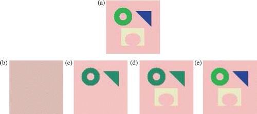
This test case exemplifies the relevance of all the iterations. All iterations are meaningful: the first step gives a monochrome image with the optimal colour (the mean colour of the picture elements); the second step gives the best splitting of the image into two zones with the best two colours; and so on.
In the second example, the image to be segmented, , is a perturbation of the previous image, , with small square inclusions in the yellow, blue and green patterns. Iteration results are illustrated from . The four first iterations do not detect the perturbations, and the fourth is exactly the final segmentation of the non perturbed image (to be correct, only the partition associated with it is the same). The last three iterations successively detect the three perturbations.
Figure 2. A perturbation of the simple example: (a) is the image to segment, and (b)–(h) are the seven successive iterations of the adaptive parameterization algorithm.
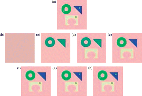
This second example shows that the larger the contrast is, the faster it is detected, which means that a stopping criterion could be the number of regions supposed to be the more relevant. Also notice that the data image is retrieved in only seven iterations, which is exactly the number of distinct colours in the perturbed data image.
3. Optimal adaptive segmentation
Adaptive segmentation algorithms have been proposed by many authors. In Citation23 level sets are used to design a robust evolution model based on adaptation of parameters with respect to data. In Citation24 the adaptivity is related to the fact that the segmentation is adapted to different regions: regions are segmented using an appropriate method according to their types. The adaptivity is achieved through the variation of the size of the neighbourhoods used for the estimation of the intensity functions in Citation25. Finally, adaptive segmentation in Citation26 is related to the use of an adaptive clustering algorithm Citation27 to obtain the specially adaptive dominant colours.
The starting point for the method proposed in this article is the adaptive multidimensional parameter estimation algorithm proposed in Citation16 for the general nonlinear inverse problem of Section 2.1. It proceeds iteratively, using multi-dimensional refinement indicators to split at each step one of the regions where the multidimensional parameter is constant. This approach allows us to control the issue of over-parameterization by stopping the refinement process when the objective function is of the magnitude of the uncertainty or noise level.
As indicated in Section 2.3, we shall adapt this algorithm to the specificities of image segmentation. The result appears as an iterative region-based vector segmentation method, initialized by a one-region segmented image of uniform colour. At each iteration, it adapts the segmentation by splitting one region. The region to be split and the location of the splitting, taken from a set of user-defined admissible cuttings, are chosen according to values of exact or first order refinement indicators as defined in Citation16,Citation28. These indicators are computed from the objective function (5) or (7) or its gradients with respect to colour components. Once the regions are given, the colour in each region is computed by a straightforward minimization process. With this choice, the new segmented image is likely to produce a significant decrease of the misfit function. The algorithm is stopped when the desired number of regions is attained, i.e. when the segmentation is fine enough to retain the information of interest, and coarse enough to avoid over-segmentation.
Note that regions need not to be necessarily connected in our approach. This feature may be considered a major drawback for some image segmentation applications that requires connected regions only. Extending our algorithm to deal with this aspect is an interesting research problem that has still to be investigated.
We describe in the next sections the specification of the adaptive parameterization technique to the vector segmentation problems (5), and its extension to the multiscalar segmentation problem (7). We recall that the original image is denoted by d = {(xi, di), i ∈ I } (data), the segmented image by c = {(xi, ci), i ∈ I } (computed).
3.1. Case of vector segmentation
Let 𝒫 be the current partition. The associated segmented image c, solution of the least-squares problem (5) for the partition 𝒫, is given by , where ℳ𝒫 : {sR, R ∈ 𝒫}↦c defined by (4) denotes the mapping that paints the pixels of each region R in 𝒫 with a given colour sR, and
is its least-squares pseudoinverse, which computes the mean value in each region. Hence once the partition 𝒫 has been chosen, the best segmented image c is simply obtained by replacing on each region R the image colour by its mean value.
So we concentrate now on the determination of a partition 𝒫 with a controlled number of regions and such that J(c) is as small as possible.
3.1.1. Refinement indicators: how good is a cutting?
Let us first denote by C the cutting which splits a region R of 𝒫 into two subregions R+ and R−. In order to evaluate the effect of this additional degree of freedom on the decrease of the objective function J(c) in the vector segmentation problem (5), one can use refinement indicators Citation28, pp. 110–111]:
Exact indicators. They consist in
On the contrary, for our problem where ℱ reduces to the identity map, J is additive with respect to regions of 𝒫, so that cC coincides with c outside of R. Its value on R is given by the simple formulas:
| |||||
First-order indicators, as defined in Citation16 for multidimensional parameters, are given by
In order to illustrate the quality of this first order indicator, we have plotted in the curves:Footnote1
Figure 3. Comparison of exact and first-order indicators for various p. Each curve corresponds to the ξ↦Pr function defined in (13). 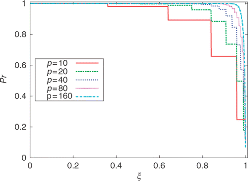 | |||||
The computational cost of first-order indicator is here similar to that of exact indicators, so one can wonder why to use an approximation when an exact calculation is available at the same price. The answer will appear in the next section.
3.1.2. Cutting strategies
Now that we know how to rank cut, the next step is to specify the cutting strategy, i.e. the family T of cuttings C to be tested for the splitting of each region.
For nonlinear problems, adaptive parameterization has been shown to be regularizing when the family T is adapted to the problem Citation29. But if enriching the cutting family always provides a better local decrease of the cost function, it can also decrease the regularizing effect by leading the algorithm into a local minimum.
However, for our segmentation problem, the forward map ℱ is the identity, so there is no danger of local minima, and we are free to choose the family T at our convenience, even if it is extremely large. So we shall consider two cutting strategies.
Best in a family. The set T of cuttings used for the tentative splitting of a region is a user-defined family of cuttings. It may incorporate any a priori information on the parameter when such information is available. We have used the set T made of all vertical and horizontal cuttings in our numerical results, which split any region R in two subregions separated by one vertical or horizontal boundary. This family of cuttings has proven useful for the nonlinear parameter estimation problem, where one seeks to describe the parameter by regions with simple forms (see, e.g. Citation30, where T also contained diagonal and checkerboard cuttings). But we shall see in the numerical results section that it seems much less adapted to image segmentation. In any case, the number of cuttings to be tested with this strategy is bounded from above by the sum of the number of horizontal and vertical pixels in the image to be segmented. Hence the best tentative cutting | |||||
Overall best. Here T is made of all possible 2-partitions of the region R. So the number of cuttings to be tested for the determination of We now describe the analytical determination of | |||||
Since we have no theoretically funded way to choose a predefined set of cuttings among which to select the refinement, the overall best cutting strategy will be the default option for image segmentation.
3.1.3. Updating the partition 𝒫
The algorithm computes the optimal cuttings for each region R of the current partition 𝒫 as indicated in Section 3.1.2, and determines the region R⋆ with the largest exact refinement indicator.
The next partition 𝒫⋆ is then obtained by splitting region R⋆ according to cutting , thus increasing the number of regions by one. The new segmented image c⋆ is updated by formula (9) over the region R⋆, and coincides with c over all other regions.
After n iterations, the vector segmentation algorithm adds n regions to the initial partition.
3.1.4. Optimal adaptive vector segmentation algorithm
We summarize here the algorithm for the vector segmentation of an image d. Let I(C) denote the best available refinement indicators for the ranking of cuttings C in the chosen family T (Section 3.1.2).
Specify the cutting strategy. Choose one from:
| • | best in a family (and then I(C) = ΔJ = exact indicators), | ||||
| • | overall best (and then I(C) = ‖λ‖∞ = first order indicators). | ||||
Initialization.
| 1. | Define the initial partition 𝒫1 as the 1-region partition of the domain D of d. | ||||
| 2. | Compute the associated 1-region segmented image:
| ||||
Iterations. For n ≥ 1, continue until the desired number of regions is attained:
| 1. | For all regions R of the current partition 𝒫n,
| ||||||||||||||||
| 2. | Retain the region R⋆ whose best cutting | ||||||||||||||||
| 3. | Define the next partition 𝒫n+1 by splitting R⋆ according to cutting | ||||||||||||||||
| 4. | Define the next segmented image | ||||||||||||||||
Remark 1
When ℱ is not the identity operator, one can use, for the best in a family cutting strategy, the first-order indicators in step (3a) instead of the exact ones if the cost of an exhaustive search with the exact indicators is too high (see the adaptive parameterization algorithm Citation16).
Remark 2
It is of course possible to start the algorithm from any partition 𝒫1 instead of a 1-partition.
3.2. Case of multiscalar segmentation
In order to construct a multiscalar segmentation, one notice that (7) is equivalent to
(18)
under the same constraint that the number of regions of the partitions 𝒫k is ‘small compared to the number of pixels of d ’.
This suggests to apply a scalar version of the previous optimal adaptive segmentation algorithm independently to each component k = R, G, B. If 𝒫 = (𝒫R, 𝒫G, 𝒫B) denotes the current multiscalar partition, this will produce three tentative optimal partitions (𝒫R#, 𝒫G#, 𝒫B#). It will then be necessary to choose one multiscalar strategy to decide how to use this information to define the updated multiscalar segmentation 𝒫⋆ = (𝒫R⋆, 𝒫G⋆, 𝒫B⋆).
3.2.1. Scalar optimal adaptive segmentation
For a given colour component k, the scalar algorithm follows the steps of Section 3.1.4 with the following minor adaptations.
Let 𝒫k be the current partition for component k. The associated k-th component segmented image, solution of (18) for the partition 𝒫k, is now given by , where
denotes the mapping that attributes the segmented intensity
to colour component k on each region R of partition 𝒫k, and
its least-squares pseudoinverse, which computes the mean value of the k-th component over each region.
The refinement indicators associated with a cutting C which splits a region R of the current k-th component partition 𝒫k into two subregions R+ and R− are (compare with Section 3.1.1):
Exact indicators:
| |||||
First-order indicators:
Of course, exact and first-order indicators are still linked by relation (12). | |||||
In the absence of specific information for each component, we have chosen to use the same set T of tentative cuttings for each colour component k. So the cutting strategies are (cf. Section 3.1.2) the following.
Best in a family. T is a predefined family of cuttings, for example the set of vertical and horizontal cuttings. With this strategy, the best cutting | |||||
Overall best. T is made of all possible 2-partitions of the region R. Here the best cutting | |||||
So after one iteration of the scalar algorithm has been performed on each component k, the following quantities are available:
(22)
(23)
3.2.2. Updating the partition 𝒫 = (𝒫R, 𝒫G, 𝒫B): multiscalar strategy
We now describe three multiscalar strategies which can be applied to update the current multiscalar partition 𝒫 once the results (22) and (23) of the scalar algorithm have been obtained for each colour component:
Best component only. This strategy determines the colour component k⋆ whose tentative refinement produces the largest decrease ΔJk#, and applies the corresponding optimal partition | |||||
Best component for each. In this strategy, the algorithm refines each component k according to the corresponding tentative optimal partition 𝒫k# determined by the scalar algorithms. The current and updated multiscalar partitions are then
The best component for each multiscalar strategy amounts to apply the scalar refinement indicator algorithm to each component separately, i.e. to use the tensor product of the three algorithms. | |||||
Combine best components. Here the algorithm selects the three optimal cuttings In contrast with the vector segmentation algorithm of Section 3.1.4, the combine best components multiscalar strategy adds at each iteration between 3 and 23 − 1 regions to the current vector partition. So the number of regions may increase rapidly, which is not compatible with the idea of adaptive parameterization. | |||||
Note that all multiscalar strategies are equivalent in the scalar case.
3.2.3. The multiscalar adaptive segmentation algorithm
We summarize here the adaptation of the algorithm of Section 3.1.4 to the determination of multiscalar segmentations.
Specify the cutting strategy. Choose one from:
| |||||||||||||||||||||||||||||||||||||||||||||||||||||||||||||||||||||||||||||
Specify the multiscalar strategy. Choose one from:
| |||||||||||||||||||||||||||||||||||||||||||||||||||||||||||||||||||||||||||||
Initialization. Define
| |||||||||||||||||||||||||||||||||||||||||||||||||||||||||||||||||||||||||||||
Iterations. For n ≥ 1, continue until the desired number of regions is attained:
| |||||||||||||||||||||||||||||||||||||||||||||||||||||||||||||||||||||||||||||
Remark 3
It is of course possible to start the algorithm from any multiscalar partition 𝒫1 instead of three 1-partitions, with the restriction that 𝒫1 has to be a vector partition in case the combine best components multiscalar strategy is used.
Remark 4
Note that for both the vector and multiscalar segmentations, the expressions to compute are simple closed-form formulas that are local to regions. Furthermore, in steps (3a) and (3b) the best cutting for each region and its associated exact indicator are invariant as long as the region is not split. Hence, an iteration of the algorithm only amounts to compute step (3) for the two new subregions (of the retained region R⋆) that appeared in the partition 𝒫n at the previous iteration. Taking into account this optimization, it is obvious to derive a linear version of the algorithm (in terms of the number of iterations), which is a salient aspect of this approach.
4. Numerical results
In this section we illustrate the numerical behaviour of algorithms of Sections 3.1.4 and 3.2.2 for the adaptive vector and multiscalar segmentations. The image d to be segmented is the picture of a colourful sculpture Citation31. Its definition is 400 × 533 (i.e. 213,200 pixels).
Note that the original image d is itself trivially a segmented image, with a number of regions equal, for a vector segmentation, to the number of distinct colours – here 55,505 –, or equal, for each component for a multiscalar segmentation, to the number of distinct levels in the component – here the maximum of 256 levels for a 24-bit colour image is reached for all components. Hence, if no constraint is set on the number of regions, the above-mentioned the adaptive segmentation algorithms will converge towards the original image d. But, though regions are introduced in our algorithms with parsimony at each iteration, for the time there is no mathematical proof that they will produce a segmented image c identical to d as soon as the number of regions in c becomes equal to that of the trivial segmentation of d. But c will for sure end up being identical to d at some point before the number of its regions equals the number of its pixels.
This convergence property is important as it ensures that by properly stopping the algorithm, one can control the compromise between the number of regions of the segmentation and the resemblance of the segmented image to the original one. The software used to compute these numerical examples is still under development, but it will be available soon at http://refinement.inria.fr/.
4.1. Vector segmentation
We first test the vector segmentation algorithm 3.1.4 with two cutting strategies. Here the algorithm adds exactly one region at each iteration, so it is easy to specify a stopping criterion providing a segmentation into exactly n regions with uniform colours.
4.1.1. Best in a family cutting strategy
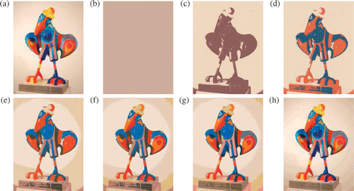
The images shown in are obtained with a quite scarce predefined family of vertical and horizontal cuttings: regions are rectangles, and the only cuttings to be tested in each region are its horizontal and vertical divisions into two equal parts. For instance, the first cutting is vertical as shown in , and all regions in are rectangular. The exact indicators are used to rank all cuts.
Figure 4. Vector segmentation with the best in a family cutting strategy. (a) is the image data to segment. Then, for each displayed image, we give the iteration number n, the number of regions nvr, and the percentage of explained data τ. (b) n = 0, nvr = 1, τ = 65.0%; (c) n = 1, nvr = 2, τ = 65.1%; (d) n = 10, nvr = 11, τ = 68.7%; (e) n = 40, nvr = 41, τ = 73.4%; (f) n = 200, nvr = 201, τ = 82.2%. Picture reproduced from a sculpture by Les Popille Citation31.
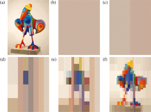
The adaptive character of the algorithm is clear on images where regions are extremely irregular. At each iteration, the cutting providing the largest decrease of the cost function is selected.
The convergence of the algorithm is very slow: the image obtained after 200 iterations is made of 200 monochrome rectangles, but it bears only a rough resemblance to the data. So it seems that the best in a family cutting strategy is not well suited for segmentation purpose – even though it remains a very good strategy for the general problem of vector parameter estimation.
4.1.2. Overall best cutting strategy
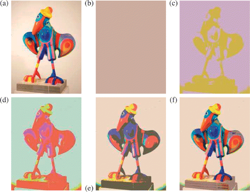
We present in the vector segmentation of the same image with the overall best cutting strategy. Here the shape of the regions are perfectly adapted to the image data: the image is already recognizable with only three regions, see , and the algorithm is able to explain 86.8% of the data with as few as six colour regions (). But it takes 41 colour regions to explain up to 94.8% of the data. In any case, the intermediate images generated by the algorithm offer a large choice of segmented images to choose from.
Figure 5. Vector segmentation with the overall best cutting strategy. (a) is the image data to segment. Then, for each displayed image, we give the iteration number n, the number of regions nvr, and the percentage of explained data τ. (b) n = 0, nvr = 1, τ = 65.0%; (c) n = 1, nvr = 2, τ = 77.9%; (d) n = 2, nvr = 3, τ = 82.1%; (e) n = 5, nvr = 6, τ = 86.8%; (f) n = 7, nvr = 8, τ = 88.1%; (g) n = 10, nvr = 11, τ = 89.6%; (h) n = 40, nvr = 41, τ = 94.8%. Picture reproduced from a sculpture by Les Popille Citation31.
It is this configuration of the algorithm (vector segmentation with overall best cutting strategy) which was used to run the example of . There also, as we have seen in Section 2.4, the intermediate iterations are pertinent as they let us discover progressively the smaller perturbations.
In conclusion, the overall best cutting strategy seems to be well adapted to image segmentation purposes, so we have used it in all the numerical results below.
4.2. Multiscalar segmentation
For the general parameter estimation problem, multiscalar segmentation is a natural approach when each component of the vector parameter has a different physical interpretation. This is not the case for image segmentation, where the three colour components have the same status. But one can expect that allowing a different partition for each component will allow to represent the image with a smaller number of regions for a same level of details. All tests in this section have been performed with the overall best cutting strategy.
4.2.1. The best component only multiscalar strategy
Here one iteration of the algorithm adds exactly one scalar degree of freedom to the component which produces the largest decrease of the objective function. Hence, one can expect to obtain a good representation of the original image with fewer component regions. This is confirmed by the comparison of and : the best component only multiscalar strategy explains 90% of the data with only 9 scalar regions (which generate 26 colour regions), whereas the vector segmentation algorithm requires 11 colour regions, which correspond to 33 component regions.
Figure 6. Multiscalar segmentation with the overall best cutting strategy and the best component only multiscalar strategy. (a) is the image data to segment. Then, for each displayed image, we give the iteration number n, the number of scalar regions nsr, the resulting number of uniform colour regions nvr, and the percentage of explained data τ. (b) n = 0, nsr = 3, nvr = 1, τ = 65.0%; (c) n = 1, nsr = 4, nvr = 2, τ = 70.0%; (d) n = 2, nsr = 5, nvr = 4, τ = 75.6%; (e) n = 3, nsr = 6, nvr = 8, τ = 82.8%; (f) n = 6, nsr = 9, nvr = 26, τ = 90.1%. Picture reproduced from a sculpture by Les Popille Citation31.
4.2.2. The best component for each multiscalar strategy
The control on the number of degrees of freedom is less precise with this algorithm, as one iteration adds exactly three scalar degrees of freedom instead of one for the previous algorithm.
Note that the images of and coincide: this means simply that the three first iterations – after the three initialization ones – of the best component only algorithm have updated successively the R, G and B components. But when the number of iterations increases, it can be expected that the best component only algorithm will not cycle regularly through the R, G and B components as the best component for each does, and hence produce better images for a given number of component regions.
Figure 7. Multiscalar segmentation with the overall best cutting strategy and the best component for each multiscalar strategy. (a) is the image data to segment. Then, for each displayed image, we give the iteration number n, the number of scalar regions nsr, the resulting number of vector regions nvr, and the ratio of explained data τ. (b) n = 0, nsr = 3, nvr = 1, τ = 65.0%; (c) n = 1, nsr = 6, nvr = 8, τ = 82.8%; (d) n = 2, nsr = 9, nvr = 26, τ = 90.1%; (e) n = 5, nsr = 18, nvr = 153, τ = 94.7%; (f) n = 10, nsr = 33, nvr = 4581, τ = 97.1%. Picture reproduced from a sculpture by Les Popille Citation31.
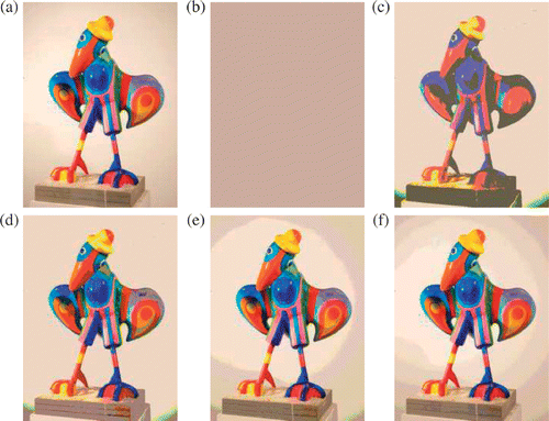
Because of the complete independence of the partitions for the R, G and B components, the number of colour regions obtained by superimposition of the component regions blows up for these two algorithms (). This shows that the parameterization of the image by component regions instead of colour regions allows a drastic reduction of the number of regions for a given image quality. In other words, it is possible with these multiscalar algorithms to obtain a segmented image with a large number of colour regions, described by a much smaller number of component regions.
4.2.3. The combine best components multiscalar strategy
This multiscalar strategy in fact produces a vector segmentation, as we have seen in the last item of Section 3.2.2. Hence, all current component images are segmented on the same partition, so we have omitted the number nsr of scalar regions in , as it is given by nsr = 3nvr.
Figure 8. Multiscalar segmentation with the overall best cutting strategy and the combine best components multiscalar strategy. (a) is the image data to segment. Then, for each displayed image, we give the iteration number n, the number of uniform colour regions nvr, and the percentage of explained data τ. (b) n = 0, nvr = 1, τ = 65.0%; (c) n = 1, nvr = 8, τ = 84.1%; (d) n = 2, nvr = 12, τ = 88.3%; (e) n = 5, nvr = 24, τ = 91.4%; (f) n = 10, nvr = 42, τ = 94.1%. Picture reproduced from a sculpture by Les Popille Citation31.
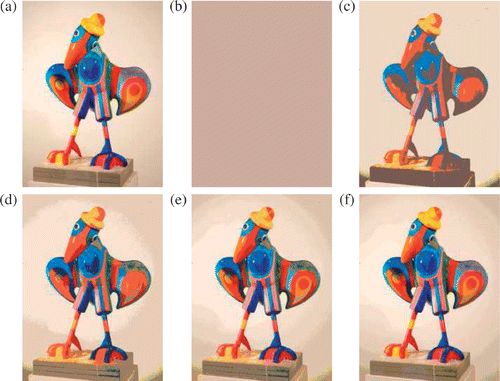
Comparison of and with shows that, for a given level of accuracy, the combine best components multiscalar strategy tends to produce vector segmented images with a larger number of regions than the direct vector segmentation algorithm.
Also, the algorithm adds at each iteration a number of colour regions between 3 and 7, i.e. between 9 and 21 scalar degrees of freedom, which makes it more difficult to control of the number of colour regions.
So on a whole, the combine best components multiscalar strategy seems to perform less for image vector segmentation than the direct vector segmentation algorithm 3.1.4.
5. Conclusion
Once recognized as a parameter estimation problem, for which the forward modelling map to invert is the identity, image segmentation may benefit from the theory of optimal control.
We have studied the specificities of this favourable case in the context of adaptive parameterization and we have proposed an optimal adaptive (vector) segmentation algorithm. This algorithm provides a finite sequence of segmented images with a number of colour regions increasing by one at each iteration. Thanks to its adaptive character, the algorithm extracts the significant regions from the very beginning, and all the intermediate steps of the process are meaningful. The optimal character indicates that the most significant regions are extracted first, and that the sequence minimizes the error with respect to the original image and terminates with a segmented image containing as many regions as distinct colours in the original image corresponding to the null error. This algorithm is well-suited to finely control the desired number of colour regions, since it is equipped with a meaningful criterion to stop the refinement process.
The study has also exhibited a class of multiscalar algorithms that provide a distinct segmentation for each colour component. Here the number of component regions increases by one or three at each iteration, but the number of resulting colour regions blows up quickly, thus explaining a large percentage of the data. Hence, this algorithm also shines when a desired percentage of the data has to be explained with a number of (component) regions as small as possible.
Acknowledgements
This research was partially carried out as part of the DGRSRT/INRIA STIC project “Identification de paramètres en milieu poreux: analyse mathématique et étude numérique” and of the ENIT/INRIA Associated Team MODESS. The authors hereby acknowledge the provided support. The authors would also like to thank Les Popille for their kind permission to use a reproduction of one of their sculptures.
Notes
1. Since in (12), we have , we also have
, and thus
.
References
- Pal, NR, and Pal, SK, 1993. A review on image segmentation techniques, Pattern Recogn. 26 (1993), pp. 1277–1294.
- Spirkovska, L, 1993. A Summary of Image Segmentation Techniques. California: Technical Memorandum 104022, NASA, AMES Research Center, Moffett Field; 1993.
- Skarbek, W, and Koschan, A, 1994. Colour Image Segmentation – A Survey. Berlin: Technischer Bericht 94-32, Technical University of Berlin; 1994.
- Baillie, JC, , Segmentation, ENSTA, 2003 Module D9, ES322 – Traitement d'Image et Vision Artificielle.
- Muñoz, X, Freixenet, J, Cufí, X, and Martí, J, 2003. Strategies for image segmentation combining region and boundary information, Pattern Recogn. Lett. 24 (2003), pp. 375–392.
- Pavlidis, T, 1980. Structural Pattern Recognition. New York: Springer-Verlag; 1980.
- Pietikäinen, M, Rosenfeld, A, and Walter, I, 1982. Split-and-link algorithms for image segmentation, Pattern Recogn. 15 (1982), pp. 287–298.
- Chakraborty, A, and Duncan, JS, 1995. "Integration of boundary finding and region-based segmentation using game theory". In: Bizais, Y, Barillot, C, and Di Paola, R, eds. Information Processing in Medical Imaging. Dordrecht: Kluwer Academic Publishers; 1995. pp. 189–201.
- Fan, J, Yau, D, Elmagarmid, A, and Aref, W, 2001. Automatic image segmentation by integrating colour-edge extraction and seeded region growing, IEEE Trans. Image Process. 10 (2001), pp. 1454–1466.
- Koepfler, G, Lopez, C, and Morel, JM, 1994. A multiscale algorithm for image segmentation by variational method, SIAM J. Numer. Anal. 31 (1994), pp. 282–299.
- Geman, S, and Geman, D, 1984. Stochastic relaxation, Gibbs distributions and the Bayesian restoration of images, IEEE Trans. Pattern Anal. Machine Intel. 6 (1984), pp. 452–472.
- Philipp-Foliguet, S, and Guigues, L, 2006. New criteria for evaluating image segmentation results, in Proceedings of IEEE International Conference on Acoustics Speech and Signal Processing, Vol. II. 2006. pp. 109–112.
- Uchiyama, T, and Arbib, M, 1994. Color image segmentation using competitive learning, IEEE Trans. Pattern Anal. Machine Intel. 16 (1994), pp. 1197–1206.
- Bonilla, LL, 2008. Inverse Problems and Imaging, Lecture Notes in Mathematics. Vol. 1943. New York: Springer; 2008.
- Wu, X, 1993. Adaptive split-and-merge segmentation based on piecewise least-square approximation, IEEE Trans. Pattern Anal. Machine Intel. 15 (1993), pp. 808–815.
- Ben Ameur, H, Clément, F, Weis, P, and Chavent, G, 2008. The multidimensional refinement indicators algorithm for optimal parameterization, J. Inverse Ill-Posed Probl. 16 (2008), pp. 107–126.
- Cheng, HD, Jiang, XH, Sun, Y, and Wang, J, 2001. Color image segmentation: Advances and prospects, Pattern Recogn. 34 (2001), pp. 2259–2281.
- Nadernejad, E, Sharifzadeh, S, and Hassanpour, H, 2008. Edge detection techniques: evaluations and comparisons, Appl. Math. Sci. 31 (2008), pp. 1507–1520.
- Borenstein, E, and Ullman, S, 2008. Combined top-down/bottom-up segmentation, IEEE Trans. Pattern Anal. Machine Intel. 30 (2008), pp. 2109–2125.
- Tremeau, A, and Borel, N, 1997. A region growing and merging algorithm to colour segmentation, Pattern Recogn. Lett. 13 (1997), pp. 561–568.
- Ohta, Y, Kanade, K, and Sakai, T, 1980. Color information for region segmentation, Comput. Graphics Image Process 13 (1980), pp. 222–241.
- Tominaga, S, "Color image segmentation using three perceptual attributes". In: IEEE Proceedings of the Conference on Computer Vision and Pattern Recognition, 1986, pp. 626–630.
- Baillard, C, Barillot, C, and Bouthemy, P, , Robust Adaptive Segmentation of 3D Medical Images with Level Sets, 1369, Irisa, Rennes, France, 2000.
- Rosenberg, C, Chehdi, K, and Kermad, C, 2000. Adaptive Segmentation System. Vol. 2. in Proceedings of the 5th International Conference on Signal Processing; 2000, pp. 918–921.
- Pachai, C, Zhu, YM, Guttmann, CRG, Kikinis, R, Jolesz, FA, Gimenez, G, Froment, JC, Confavreux, C, and Warfield, SK, "Unsupervised and adaptive segmentation of multispectral 3D magnetic resonance images of human brain: A generic approach". In: Proceedings of the Fourth International Conference on Medical Image Computing and Computer-Assisted Intervention (MICCAI-2001), 2001, pp. 1067–1074.
- Chen, J, "Adaptive image segmentation based on color and texture". In: Proceedings of the International Conference on Image Processing (ICIP), 2002, pp. 789–792.
- Pappas, TN, 1992. An adaptive clustering algorithm for image segmentation, IEEE Trans. Signal Process. 40 (1992), pp. 901–914.
- Chavent, G, 2010. Nonlinear Least Squares for Inverse Problems. Vol. XIV. Berlin: Scientific Computation, Springer; 2010.
- Ben Ameur, H, and Kaltenbacher, B, 2002. Regularization of parameter estimation by adaptive discretization using refinement and coarsening indicators, J. Inverse Ill-Posed Probl. 10 (2002), pp. 561–583.
- Ben Ameur, H, Chavent, G, and Jaffré, J, 2002. Refinement and coarsening indicators for adaptive parameterization: Application to the estimation of hydraulic transmissivities, Inverse Probl. 18 (2002), pp. 775–794.
- Les Popille, Gros Bec à chapeau jaune en short. Available from http://www.popille.fr/archives/nondispo/18-GrosBecAChapeauJauneEnShort.htm.