Abstract
The radiative transfer in multi-layer composite media has numerous applications, for example, in regional and global climate models, Solar System bodies research, Earth remote sensing, and multi-layer clouds studies, among others. In this study, we focus on the inverse analysis of the radiative transfer problem in a two-layer plane-parallel medium. For the direct problem solution, we use the well-known Chandrasekhar's discrete ordinates method combined with the finite difference method. We are interested in the estimation of the scattering and absorbing coefficients using the measured data of the emerging radiation at both boundary surfaces of the medium and also at the interface between the two layers. The inverse problem is implicitly formulated and the minimization of the defined objective function is achieved with the Levenberg–Marquardt method. The solutions obtained are investigated in the face of the sensitivity analysis.
1. Introduction
The inverse analysis of radiative transfer in participating media has several practical applications such as optical tomography Citation1, computerized tomography Citation2, coupled atmospheric-ocean models Citation3, hydrologic optics Citation4, and radiative properties estimation Citation5–7. In most cases, it is usually assumed that the investigated medium is homogeneous, but in many applications, this assumption is not valid and a good number of papers have also been published looking at radiative transfer in multi-layer composite media, with applications, for example, in regional and global climate models Citation8,Citation9, Solar System bodies research Citation10,Citation11, Earth remote sensing Citation12–14, and multi-layer clouds studies Citation15,Citation16.
Radiation sensors are thus essential to many applications in medicine, industry, research, and space technology, for example in safety, security, quality control, diagnosis, and treatment, being a subject of intense research Citation17. Even though most applications deal with non-intrusive measurements, in many cases, internal measurements are essential and the development of internal probes is also of relevant interest Citation18–21. In fact, there has been an increasing interest in finding new materials which can be used in the fabrication of radiation sensors Citation22,Citation23 and more recently, Ahmadi and Yeow Citation24 investigated the development of radiation sensors based on bacteriorhodopsin, showing potential applications in the fabrication of micrometre and nanometre scale devices.
In this context, this study investigates the determination of the absorption and scattering coefficients in layered structures by performing measurements of the radiation intensity that leaves the medium at different polar angles. When dealing with fluid media, which encompasses sea water and cloud studies, with applications in climate models, hydrologic optics, and remote sensing, among others, nowadays, technology relating to radiation sensors allows for radiation intensity measurements at inner positions and therefore, cases in which internal measurements at the interface are available are also investigated.
For the direct radiative transfer problem solution in a two-layer plane-parallel medium, we use the well-known Chandrasekhar's discrete ordinates method combined with the finite difference method. The inverse problem is implicitly formulated, and the minimization of an objective function given by the summation of the squared residues between a calculated quantity and a measured one becomes the main focus.
The minimization of the objective function is generally tackled by means of deterministic methods Citation25, heuristics Citation26–29, or combinations of both Citation30. Independent of the approach employed in the minimization procedure, the sensitivity analysis plays a major role in several aspects related to the formulation and solution of inverse problems Citation31,Citation32. Thus, a sensitivity analysis is performed on the data acquired with external and internal detectors. The inverse problem is then iteratively solved with Levenberg–Marquardt method and the solutions obtained are critically discussed.
2. Mathematical formulation and solution of the direct problem
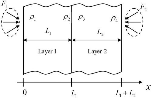
Consider the problem of radiative transfer in a composite medium with two plane-parallel, isotropically scattering, grey layers, with diffusely reflecting boundary surfaces and interface, as shown in . The medium is subjected to external irradiation on both sides with intensity at
and
at
.
and
represent the thicknesses of layers 1 and 2, respectively.
The mathematical formulation of the direct radiative transfer problem with azymuthal symmetry is given by
Layer 1:
(1)
(2)
(3)
Layer 2:
(4)
(5)
(6)
where
represents the radiation intensity in layer
, with
or
and
the total extinction coefficient,
(7)
where
is the absorption coefficient,
the scattering coefficient,
the cosine of the polar angle, and
are the diffuse reflectivities, with
. Observe that in Equations (1c) and (2b), we have considered that both reflection and transmission are diffuse at the interface between the two layers.
Considering the definition of the dimensionless optical variable,
(8)
The optical thickness of the medium, , can be obtained by integrating the whole spatial domain, i.e. from
up to
,
(9)
With this definition, the radiative transfer equations can be rewritten in a dimensionless form and what comes to light is the definition of the single-scattering albedo, , which is the ratio between the scattering coefficient and the total extinction coefficient,
(10)
Even though the dimensional formulation was considered in this study, in the presentation of the test cases, we make reference to the dimensionless single-scattering albedo and optical thickness.
When the geometry, the radiative properties, and the boundary conditions are known, problem (1–2) may be solved yielding the values of the radiation intensities , for
and
, and
, for
and
. This is the direct problem.
In order to solve the direct problem, we have used Chandrasekhar's discrete ordinates method Citation33. The polar angle and the spatial domains are discretized, the integral terms on the right hand side of Equations (1) and (2) are replaced by Gaussian quadratures, and a finite-difference approximation is used for the terms on the left hand side of Equations (1a) and (2a). With that, and
are determined for all spatial and angular nodes of the discretized computational domain.
3. Mathematical formulation and solution of the inverse problem
In this study, we are interested in obtaining estimates for the vector of unknowns
(11)
using measured data of the emerging radiation intensity at the boundary surfaces
and
, and also at the interface between the two layers, i.e.
, represented by
, with
, being
the total number of experimental data.
As real experimental data were not available, we generated sets of synthetic experimental data with
(12)
where
represents the calculated values of the radiation intensity using the exact values of the radiative properties,
, which in a real application is not available and we want to determine with the inverse problem solution,
simulates the standard deviation of the measurement errors, and
is a random number, from a Gaussian distribution with zero mean and unitary standard deviation.
3.1. Inverse problem formulation
In this study, it is considered that the external detectors are able to acquire experimental data, being half acquired at
, at the polar angles corresponding to
with
, and half at
, at the polar angles corresponding to
with
. The internal detectors are also able to acquire
experimental data at the interface
, at the same polar angles with
,
. Therefore,
.
As the number of measured data, , is usually much larger than the number of parameters to be estimated,
, the inverse problem is formulated as a finite dimensional optimization problem Citation34 in which we seek to minimize the least-squares norm
(13)
where
represents the calculated value of the radiation intensity (using estimates for the unknown radiative properties
) at the same boundary, and at the same polar angle, for which the experimental value
is obtained. The elements of the vector of residues
are given by
(14)
3.2. Inverse problem solution
The solution of the inverse problem here considered is achieved with the minimization of the objective function described by Equation (9). For that purpose, in this study, we use the Levenberg–Marquardt algorithm Citation35. Starting with an initial guess , an iterative procedure is constructed, in which new estimates are obtained with
(15)
being the correction
calculated from
(16)
where
is a damping parameter,
is the identity matrix, and the elements of the sensitivity matrix
are
(17)
The iterative procedure of sequentially calculating and
with Equations (11–13) is continued until the convergence criterion
(18)
is satisfied, where
is a prescribed tolerance. The damping factor
is varied during the iterative procedure, such that when convergence is achieved, its value is close to zero.
3.3. Confidence intervals
For normally distributed measurement errors with zero mean and constant variance, the standard deviation of the estimated parameters can be determined from the expression Citation31
(19)
Assuming a normal distribution for measurement errors and 99% confidence, the intervals for the estimated quantities are determined as
(20)
3.4. Sensitivity analysis
The sensitivity analysis plays a major role in several aspects related to the formulation and solution of inverse problems Citation32.
The elements of the sensitivity matrix , defined in Equation (13), are called the sensitivity coefficients. In order to obtain good estimates, within reasonable confidence intervals, it is required that the sensitivity coefficients are relatively high and, when two or more unknowns are simultaneously estimated, their sensitivity coefficients must be linearly independent, which graphically means that they should not present the same slope in absolute value. Otherwise
and the problem is ill-conditioned. In this study, for the sensitivity analysis, the scaled sensitivity coefficients are used
(21)
where the derivatives have been calculated using the central finite difference formula, as follows
(22)
where
were taken as 0.5% of
.
4. Results and discussion
In the examples presented in this study, the following external illumination was considered: and
, in Equations (1b) and (2c), respectively. As the initial guess,
, for the Levenberg–Marquardt algorithm, the value
was considered for all unknowns, and for the test cases presented, 20 independent runs are performed, i.e. for each run, the simulated measured intensities
are re-calculated using Equation (8), simulating 20 different experiments. The confidence intervals of the estimates are calculated using Equation (16). Next, we present three test cases, which are detailed in and . For the sake of illustration, presents sea water scattering and absorption coefficients Citation36.
Table 1. Property values for the test cases.
Table 2. Dimensionless parameters for the test cases considered.
Table 3. Sea water scattering and absorption coefficients 36.
4.1. Test Case 1
For our first test case, consider a medium composed of two plane-parallel media with the properties shown for Case 1 in . One may observe that this test case corresponds in fact to a homogeneous layer with a total thickness of .
In , the sensitivity coefficients related to the unknowns are presented at both
(
) and
(
), i.e. considering only external detectors. It can be seen that
and
are linearly dependent at
and close to zero at
. Furthermore,
and
are linearly dependent at
and close to zero at
. It means that neither
can be simultaneously estimated with
, nor
can be simultaneously estimated with
, which explains the non-uniqueness of the solution difficulties that arise when the four parameters,
,
,
and
, are simultaneously estimated with data acquired only by the external detectors Citation37. If we consider that the exact values of
and
are known, then
and
may be simultaneously estimated, i.e.
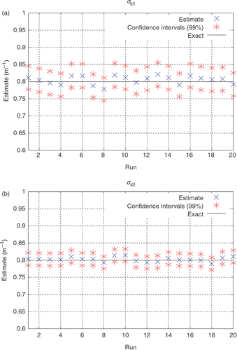
instead of the four unknowns in Equation (7). These results are presented in . It was considered
, what corresponds to an experimental error up to 5%.
Figure 2. (a and b) Scaled sensitivity coefficients for the data acquired with external detectors: Test Case 1.
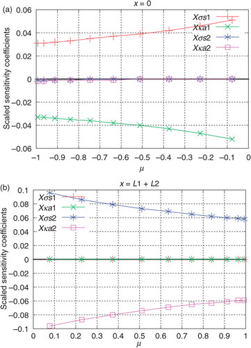
Figure 3. (a and b) Estimates obtained for σs1 and σs2 (ka1 and ka2 are considered to be known) using only external detectors, considering simulated experimental data with σe = 0.002 (up to 5% error). Test Case 1.
On the other hand, if we consider that the exact values of and
are known, then
and
may be estimated simultaneously, i.e.
. These results are shown in . It was considered
, what corresponds to an experimental error up to 5%.
Figure 4. (a and b) Estimates obtained for ka1 and ka2 (σs1 and σs2 are considered known) using only external detectors, considering simulated experimental data σe = 0.002 (up to 5% error). Test Case 1.
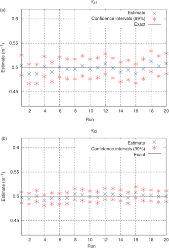
Note in and that the estimates for and
have narrower confidence intervals than those for
and
. Such behaviour was expected since
and
have higher sensitivity coefficients than
and
.
Now, we look at the sensitivity coefficients related to the data acquired by internal detectors located at for both
and
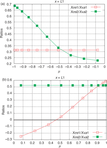
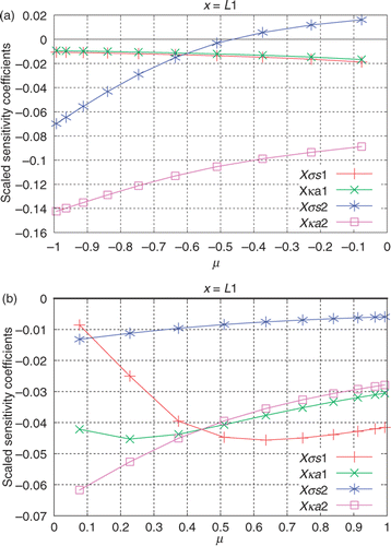
. It can be observed in that the sensitivity coefficients related to the internal detectors have lower values than those related to the external detectors (). Nonetheless, the sensitivity coefficients of the unknowns are linearly independent, what means the four parameters might be simultaneously estimated, i.e.
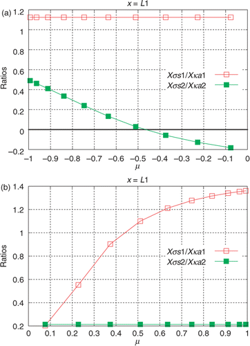
, using the data acquired with the internal detectors. In order to give an insight into the linear dependence of
with
, and
with
the ratios
and
are depicted in . In , the results of the estimation of
are shown considering the data acquired only with the internal detectors, and
, which corresponds to an experimental error up to 7%. Observe that while
led to errors of up to 5% in the experimental data related to the external detectors,
led to errors of up to 7% in the experimental data for the internal detectors. Considering
for the estimation using only the internal detectors lead to errors up to 30%, which occurs due to the small radiation intensities measured at the interface, since the layers have a high optical thickness. Even with this high-level error, the solution converges, but poor estimates are obtained, i.e. with wide confidence intervals. For the sake of brevity, these results are not shown here.
Figure 5. (a and b) Scaled sensitivity coefficients for the data acquired with internal detectors: Test Case 1.
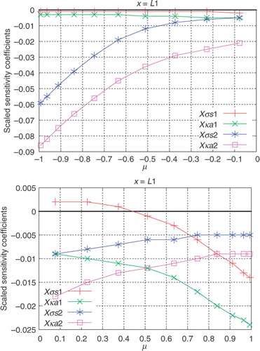
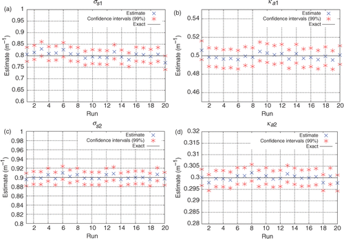
Figure 7. (a–d) Estimates obtained for σs1, ka1, σs2, ka2 using only internal detectors, considering simulated experimental data with up to 7% error: Test Case 1.
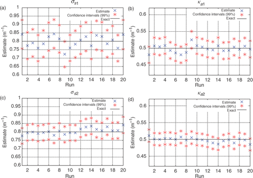
Now consider that the data of both the external and the internal detectors are available. Considering for the computation of all the simulated measured data, we have available data with moderate noise (up to 5%) acquired with the external detectors and data with high level of noise (up to 30%) acquired with the internal detectors. The good results in the estimation of
shown in leads to the conclusion that the data of the internal detectors, even with higher level of noise, act as a constraint, avoiding the non-uniqueness of the solution. In other words, it seems that one does not need accurate data from internal measurements in order to avoid the non-uniqueness of the solution.
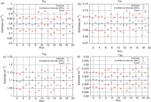
Figure 8. (a–d) Estimates obtained for σs1, ka1, σs2, ka2 using both external and internal detectors, considering simulated experimental data with up to 5% error for the external detectors measurements and up to 30% error for the internal detectors measurements: Test Case 1.
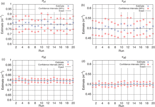
Note once again that the estimates for the properties of the layer 2 are more accurate than those for the layer 1. Observe that and
have higher sensitivity coefficients also for the internal measurements.
4.2. Test Case 2
Now consider a two-layer medium composed of two plane-parallel media with the properties shown for Case 2 in , where one may observe that the difference between the refractive indices of the two materials has been neglected, by setting the diffuse reflectivities equal to zero at the interface ( and
). In , the scaled sensitivity coefficients related to the unknowns
are presented calculated at both
(
) and
(
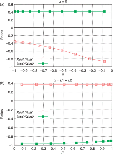
) at the same polar angles where the experimental data are acquired with the external detectors. In order to give an insight into the linear dependence of
with
, and
with
, the ratios
and
for the data acquired with the external detectors are depicted in .
Figure 9. (a and b) Scaled sensitivity coefficients for the data acquired with external detectors: Test Case 2.
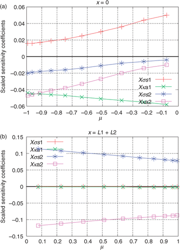
Observe in and that for the data acquired with the detector located at (
), the sensitivity coefficients with respect to
and
are correlated, while the data acquired at
are useless for the estimation of
and
, and also for the simultaneous estimation of
and
.
Regarding the simultaneous estimation of a smaller number of parameters, it was observed that the groups of unknowns (considering the exact value of
is known) and
(considering the exact value of
is known) can be well estimated using the data acquired only with the external detectors. But as our main goal is the simultaneous estimation of the four properties, i.e.
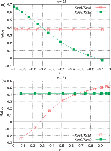
, we look once again at the data acquired by the internal detectors. In , the scaled sensitivity coefficients at
are shown for both
and
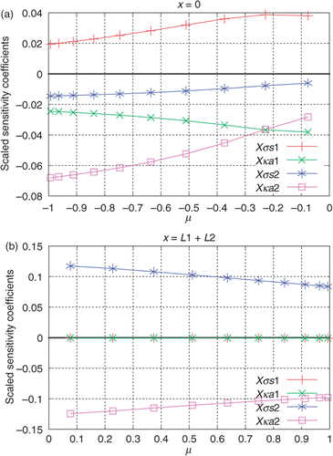
. Note that in , the sensitivity coefficients for the data acquired with the internal detectors related to
and
are linearly independent for
and those related to
and
are linearly independent for
, where they have relatively high values, suggesting that one may be able to simultaneously estimate all the four properties considered using the data acquired only with the internal detectors. These results are shown in , considering
, which corresponds to an experimental error up to 5%. Observe that for this test case,
led to the same level of noise (<5%) for the data acquired with the external or with the internal detectors.
Figure 11. (a and b) Scaled sensitivity coefficients for the data acquired with internal detectors: Test Case 2.
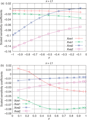
Figure 13. (a–d) Estimates obtained for σs1, ka1, σs2, ka2 using only internal detectors, considering simulated experimental data with up to 5% error: Test Case 2.
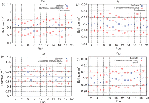
Even though good estimates have been obtained using only internal detectors, even better solutions may be achieved if we use more experimental data, augmenting the determinant of the information matrix, . shows the results when both the internal and the external detectors are used; with
, which corresponds to an experimental error up to 5%. As expected, better estimates with narrower confidence intervals are obtained. The estimates for the properties of the layer 2 were more accurate than those for the layer 1, what is expected as consequence of the higher sensitivity coefficients for
and
in comparison with
and
.
4.3. Test Case 3
Finally, we consider the Case 3 in , illustrating an example with nonzero values for the diffuse reflectivities at the interface ( and
). Figures depict the sensitivity coefficients with respect to the data acquired by external and internal detectors, which present similar behaviour to the previous cases. For this example, we have considered
yielding experimental errors up to 10%. The good estimates obtained within reasonable confidence intervals, considering the data acquired with both external and internal detectors, shown in , indicate the feasibility of the present approach even when dealing with relative high level of experimental noise.
Figure 15. (a and b) Scaled sensitivity coefficients for the data acquired with external detectors: Test Case 3.
5. Conclusions
The inverse analysis of radiative transfer in participating media has several practical applications and it is usually assumed that the investigated medium is homogeneous, but in many cases, this assumption is not valid, such as when dealing with multi-layer composite media, which occurs in many applications, for example, in regional and global climate models, Solar System bodies research, Earth remote sensing, and multi-layer clouds studies. Most inverse radiative transfer problems aim at determining unknown parameters with nonintrusive measurements of the radiation intensity. Nevertheless, when dealing with fluid media, which encompasses sea water and cloud studies, with applications in climate models, hydrologic optics and remote sensing, technology on radiation sensors allows for radiation intensity measurements at inner positions. In this study, the simultaneous determination of the scattering and absorbing coefficients in layered structures has been investigated by performing measurements at different polar angles of the radiation intensities leaving the medium and at the interface, being verified in the cases considered the necessity of measurements at the interface in order to achieve accurate results.
Acknowledgements
The authors acknownledge the financial support provided by CNPq, Conselho Nacional de Desenvolvimento Científico e Tecnológico and FAPERJ, Fundação Carlos Chagas Filho de Amparo à Pesquisa do Estado do Rio de Janeiro. They also acknowledge the remarks made by the reviewers, which significantly contributed to the improvement of the quality of the content and readability of this article.
References
- Kim, HK, and Charette, A, 2007. A sensitivity function-based conjugate gradient method for optical tomography with the frequency domain equation of radiative transfer, J. Quant. Spectrosc. Radiat. Transfer 104 (2007), pp. 24–39.
- Carita Montero, RF, Roberty, NC, and Silva Neto, AJ, 2004. Reconstruction of a combination of the absorption and scattering coefficients with a discrete ordinates method consistent with the source-detector system, Inverse Prob. Eng. 12 (1) (2004), pp. 81–101.
- Zhang, K, Li, W, Eide, H, and Stamnes, K, 2007. A bio-optical model suitable for use in forward and inverse coupled atmosphere-ocean radiative transfer models, J. Quant. Spectrosc. Radiat. Transfer 103 (2007), pp. 411–423.
- Chalhoub, ES, and Campos Velho, HF, 2001. Simultaneous estimation of radiation phase function and albedo in natural waters, J. Quant. Spectrosc. Radiat. Transfer 69 (2001), pp. 137–149.
- Nenarokomov, A, and Titov, D, 2005. Optimal experiment design to estimate the radiative properties of materials, J. Quant. Spectrosc. Radiat. Transfer 93 (2005), pp. 313–323.
- Hespel, L, Mainguy, S, and Greffet, J-J, 2003. Radiative properties of scattering and absorbing dense media: theory and experimental study, J. Quant. Spectrosc. Radiat. Transfer 77 (2003), pp. 193–210.
- An, W, Ruan, LM, and Qi, H, 2007. Inverse radiation problem in one-dimensional slab by time-resolved reflected and transmitted signals, J. Quant. Spectrosc. Radiat. Transfer 107 (2007), pp. 47–60.
- Hanan, NP, 2001. Enhanced two-layer radiative transfer scheme for a land surface model with a discontinuous upper canopy, Agric. For. Meteorol. 109 (2001), pp. 265–281.
- Tanaka, K, Yoshifuji, N, Tanaka, N, Shiraki, K, Tantasirin, C, and Suzuki, M, 2009. Water budget and the consequent duration of canopy carbon gain in a teak plantation in a dry tropical region: Analysis using a soil–plant–air continuum multilayer model, Ecol. Modell. 220 (2009), pp. 1534–1543.
- Hillier, JK, 1997. Shadow-hiding opposition surge for a two-layer surface, Icarus 128 (1997), pp. 15–27.
- Morishima, R, Salo, H, and Ohtsuki, K, 2009. A multilayer model for thermal infrared emission of Saturn's rings: Basic formulation and implications for earth-based observations, Adv. Space Res. 44 (2009), pp. 138–150.
- Verhoef, W, and Bach, H, 2003. Simulation of hyperspectral and directional radiance images using coupled biophysical and atmospheric radiative transfer models, Remote Sens. Environ. 87 (2003), pp. 23–41.
- Weng, Q, 2009. Thermal infrared remote sensing for urban climate and environmental studies: Methods, applications, and trends, ISPRS J. Photogramm. Remote Sens. 64 (2009), pp. 335–344.
- Toomey, M, Roberts, D, and Nelson, B, 2009. The influence of epiphylls on remote sensing of humid forests, Remote Sens. Environ. 113 (2009), pp. 1787–1798.
- Bennartz, R, and Preusker, R, 2006. Representation of the photon pathlength distribution in a cloudy atmosphere using finite elements, J. Quant. Spectrosc. Radiat. Transfer 58 (2006), pp. 202–219.
- Boesche, E, Stammes, P, and Bennartz, R, 2009. Aerosol influence on polarization and intensity in near-infrared O2 and CO2 absorption bands observed from space, J. Quant. Spectrosc. Radiat. Transfer 110 (2009), pp. 223–239.
- Tsoulfanidis, N, and Landsberger, S, 2010. Measurement and detection of radiation. New York: Taylor & Francis, CRC Press; 2010.
- McLean, HS, Ahmed, A, Buchenauer, D, Den Hartog, D, Domier, CW, Hill, DN, Holcomb, C, Hooper, EB, Morse, EC, Nagata, M, Roh, Y, Stallard, B, Wood, RD, Woodruff, S, Wurden, G, and Wang, Z, 2001. Plasma diagnostics for the sustained spheromak physics experiment, Rev. Sci. Instrum. 72 (1) (2001), pp. 556–561.
- Strauss, HW, Mari, C, Patt, BE, and Ghazarossian, V, 2006. Intravascular radiation detectors for the detection of vulnerable atheroma, J. Am. Coll. Cardiol. 47 (2006), pp. 97–100.
- Mukari, T, Nohara, R, Ogawa, M, Ishino, S, Kambara, N, Kataoka, K, Kanoi, T, Saito, K, Motomura, H, Konishi, J, and Saji, H, 2004. A catheter-based radiation detector for endovascular detection of atheromatous plaques, Eur. J. Nucl. Med. Mol. Imaging 31 (2004), pp. 1299–1303.
- Sato, F, Shinohe, K, Takura, T, Matsuki, H, Yamada, S, and Sato, T, 2009. Development of wireless communication system in real-time internal radiation dose measurement system using magnetic field, J. Appl. Phys. 105 (7) (2009), pp. 07B319–07B319-3.
- Gao, X, Kang, QS, Yeow, JTW, and Barnett, R, 2010. Design and evaluation of quantum dot sensors for making superficial x-ray energy radiation measurements, Nanotechnology 21 (28) (2010), p. 285502.
- Ma, J, Yeow, JTW, Chow, JCL, and Barnett, RB, 2008. A carbon fiber-based radiation sensor for dosimetric measurement in radiotherapy, Carbon, 46 (14) (2008), pp. 1869–1873.
- Ahmadi, M, and Yeow, JTW, 2011. Fabrication and characterization of a radiation sensor based on bacteriorhodopsin, Biosens. Bioelectron. 26 (2011), pp. 2171–2176.
- Silva Neto, AJ, and Özisik, MN, 1995. An inverse problem of simultaneous estimation of radiation phase function, albedo and optical thickness, J. Quant. Spectrosc. Radiat. Transfer 43 (4) (1995), pp. 397–409.
- Qi, H, Ruan, LM, Zhang, HC, Wang, YM, and Tan, HP, 2007. Inverse radiation analysis of a one-dimensional participating slab by stochastic particle swarm optimizer algorithm, Int. J. Therm. Sci. 46 (2007), pp. 649–661.
- Qi, H, Ruan, LM, Shi, M, An, W, and Tan, HP, 2008. Application of multi-phase particle swarm optimization technique to inverse radiation problem, J. Quant. Spectrosc. Radiat. Transfer 109 (2008), pp. 476–493.
- Sousa, FL, Soeiro, FJCP, Silva Neto, AJ, and Ramos, FM, 2007. Application of the generalized extremal optimization algorithm to an inverse radiative transfer problem, Inverse Prob. Sci. Eng. 15 (7) (2007), pp. 699–714.
- Stephany, S, Becceneri, JC, Souto, RP, Velho, HFC, and Silva Neto, AJ, 2010. A pre-regularization scheme for the reconstruction of a spatial dependent scattering albedo using a hybrid ant colony optimization implementation, Appl. Math. Modell. 34 (2010), pp. 561–572.
- Knupp, DC, Silva Neto, AJ, and Sacco, WF, 2009. Radiative properties estimation with the Particle Collision algorithm based on a sensitivity analysis, High Temp. High Press. 38 (2009), pp. 137–151.
- Özisik, MN, and Orlande, HRB, 2000. Inverse Heat Transfer: Fundamentals and Applications. New York: Taylor & Francis; 2000.
- Beck, JV, Blackwell, B, and St. Clair, CR, 1985. Inverse Heat Conduction – Ill-Posed Problems. New York: John Wiley & Sons; 1985.
- Chandrasekhar, S, 1960. Radiative Transfer. New York: Dover Publications; 1960.
- Silva Neto, AJ, and Moura Neto, FD, 2005. Inverse Problems – Fundamental Concepts and Applications. Rio de Janeiro: Ed UERJ; 2005.
- Marquardt, DW, 1963. An algorithm for least-squares estimation of nonlinear parameters, J. Soc. Ind. Appl. Math. 11 (1963), pp. 431–441.
- Mobley, CD, 1994. Light and Water - Radiative Transfer in Natural Waters. San Diego, CA: Academic Press; 1994.
- Lobato, FS, Steffen, V, and Silva Neto, AJ, 2009. Solution of inverse radiative transfer problems in two-layer participating media with differential evolution, Inverse Prob. Sci. Eng. 18 (2009), pp. 183–195.
