Abstract
In this article, we investigate a procedure for generating signals with genetic algorithms. Signals are obtained from elementary patterns characterized by different degrees of freedom. These patterns are repeated and combined in order to reach specific signal shapes. The whole signal parametrization has to be determined by solving a difficult inverse problem of high dimensionality and strong multimodality. This can be carried out using evolutionary algorithms with the aim of finding all pattern configurations in the signal. The different signal synthesis schemes are evaluated, tested and applied to the generation of particular railway driving profiles.
1. Introduction
The design of complex electrical devices requires taking into account at a system level couplings between architecture, sizing, energy management strategy and environment Citation1. For typical systems such as electrical vehicles (EVs), the system environment is associated with specific power-driving profiles that have to be provided by all energy sources. These profiles contain a large number of features related to the system sizing, efficiency and lifetime which can be represented by specific indicators (e.g. maximal and average mission powers, statistical indexes associated with the mission power distribution). Integrating these indicators in the design process is not straightforward because of the important number of driving missions that can be imposed on the vehicle. This can be done by identifying the most representative mission from a clustering analysis of the different indicators in compliance with all driving missions Citation2. This can also be performed by finding a ‘fictitious’ mission profile that fulfills specific values of these indicators (typically critical or average values). In this case, this results in solving an inverse problem which consists in determining a particular signal shape (i.e. the fictitious power profile) in accordance with a given number of constraints. Thus, a signal synthesis approach based on evolutionary algorithms (EAs) has been developed for solving the corresponding inverse problem.
This article is organized as follows. In Section 2, the signal synthesis method based on EAs is developed. It consists of combining elementary patterns (segment, sine or cardinal sine) in order to obtain a specific shape. The characteristics of these patterns (amplitude, phase or duration) are optimized with an EA. In Section 3, the proposed approach is used for the generation of ‘fictitious’ driving profiles in the context of railway system design. Finally, conclusions are drawn in Section 4.
2. Signal synthesis based on EAs
2.1. Signal models
In this section, different models are proposed in order to generate a positive signal of maximal amplitude ΔSmax and of duration Δτs. This signal will represent in the following typical railway driving cycles, defined as the load power demand versus time, during the locomotive trail. In our signal synthesis approach, signals are represented by combining elementary pattern characterized by different degrees of freedom (typically amplitude or frequency variables). Three kinds of patterns are considered ().
Figure 1. Elementary patterns for the signal representation: (a) segment, (b) sine and (c) cardinal sine.

2.1.1. Segment model
The first signal model is obtained by combining and aggregating elementary segments defined with two parameters: the segment amplitude 0 ≤ ΔSn ≤ ΔSmax and the segment duration 0 ≤ Δtn ≤ 1 (). After all the segments are generated, a time scaling step is performed in order to fulfil the constraint related to the signal duration, i.e. ∑Δtn = Δτs.
2.1.2. Sine model
The second model is based on a Fourier series expansion Citation3. It consists of adding elementary sine harmonics defined in phase 0 ≤ φn ≤ 2π and amplitude 0 ≤ An ≤ Smax ().
(1)
where the harmonic frequency fn is the multiple of the inverse of the signal duration Δτs:
(2)
The generated signal is shifted in order to fulfil the positiveness constraint
(3)
Where
2.1.3. Cardinal sine model
The third model uses the same harmonic approach but it is obtained by adding cardinal sine functions parametrized in location 0 ≤ tn ≤ Δτs, amplitude 0 ≤ An ≤ Smax and frequency fmin ≤ fn ≤ fmax (). The mathematical expression of an elementary pattern SCn is given by Equation (4).
(4)
A similar shifting to Equation (3) is used to ensure the signal positiveness.
2.2. Signal synthesis schemes
The investigated signal synthesis approach leads to solving an inverse problem which consists of finding the characteristics of all elementary patterns in order to fulfil some specific constraints on the whole generated signal. The problem dimensionality depends on the number and the type of elementary patterns. It equals 2n for the sine and segment models and 3n for the cardinal sine model (n denoting the number of patterns). Finding a complex signal with high variability requires the increase in n and thus the difficulty of the inverse problem. Moreover, due to the particular oscillating shape of the proposed patterns (especially sine and cardinal sine patterns), the resulting inverse problems are strongly multimodal. Therefore, the use of stochastic optimization methods such as EAs is recommended. In this study, we compare the standard anisotropic evolution strategy (ES) Citation4 with two niching EAs Citation5: the clearing algorithm (CL) Citation6 and the restricted tournament selection (RTS) with self-adaptive recombination Citation7,Citation8. Moreover, two different chromosome encoding strategies have been implemented for generating signal profiles (). The first classical approach encodes the same number of patterns for all individuals in the population. The second scheme allows the parallel investigation of signal configurations with distinct number of patterns. It consists of encoding, in the chromosome, an additional gene representing the number of patterns. This number can vary from 1 to npmax, npmax denoting the maximum number of patterns. However, it should be noted that the chromosome is identical for all individuals in the population, containing the parameters associated with npmax patterns. Then, only a part of the chromosome is considered in the individual decoding according to the value of the gene associated with the number of patterns. The other genes are not expressed and can be considered as ‘recessive’. They are not used in the individual decoding but participate in crossover and mutation operations.
3. Application to the synthesis of railway driving profiles
3.1. Design of hybrid supplies for electrical locomotives
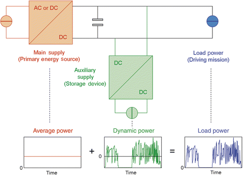
The design of hybrid power sources for electrical locomotives requires the knowledge of driving ‘missions’ (e.g. load power demand during driving cycles) for sizing the system elements Citation1. For these particular electrical architectures, a possible energy management strategy consists of providing the average part of the load power by a primary energy source Citation9,Citation10 (). The rest of the power (i.e. the fluctuant part) is devoted to a storage system (i.e. the auxiliary source). With this particular power dispatching, the size of the main supply essentially depends on the average load power Pav defined as
(5)
where ΔT denotes the mission duration and Pload represents the load power required by the mission.
Figure 3. Typical architecture of hybrid locomotive with storage and associated energy management strategy.

On the other hand, the size of the storage device can be characterized in terms of power, according to the maximal power imposed to this auxiliary supply, i.e. Pmax–Pav where Pmax represents the maximal load power during the mission. It also depends on the maximum energy quantity Eu transferred to the storage device. This energy can be computed as
(6)
where the storage energy level Es is defined as follows:
(7)
It can be seen from the previous equations that the global sizing of the hybrid electrical architecture is related to the three following factors: Pmax, Pav and Eu computed with regard to the driving mission.
In addition to these sizing indicators, two performance criteria should be considered in order to characterize driving profiles. The first criterion is an indicator of the storage device lifetime which can be expressed as the number of cycles Ncycles imposed to the storage device Citation1,Citation11. This number can be computed from the evolution of the storage device state of charge during the driving mission, using the rainflow counting method Citation12. The second criterion is the cumulative distribution function CDF (Pload) computed with the corresponding probability density function (pdf) associated with the load power variations during the mission. illustrates this criterion for a particular driving profile Pload(t).
Figure 4. Typical power profile with corresponding pdf and CDF: (a) load profile Pload(t), (b) pdf(Pload(t)) and (c) CDF(Pload(t)).

As the system efficiency generally differs for different load power values, this statistic indicator should be considered in order to assess the global system efficiency. Finally, it should be noted that sizing and performance criteria previously defined (i.e. Pmax, Pav, Eu, Ncycles, and CDF(Pload)) are capable of characterizing a driving profile in terms of temporal, frequency and statistics features. The complexity associated with the design of hybrid electric system for railway applications (or more generally with EVs) is related to the fact that they have to fulfil a set of driving missions instead of a unique mission. To overcome this problem, the design of hybrid electric systems can be carried out by separately simulating all driving missions of the data set. However, this solution generally increases the computing time of design models in an optimization context. We propose a second approach which consists in finding a fictitious driving profile including all features of the set of driving missions (i.e. critical value of the sizing indicators and average values of the performance criteria). Such profile can be obtained from target values of the sizing and performance criteria by solving the corresponding inverse problem with the signal synthesis scheme proposed in Section 2. This approach will be more deeply investigated in Section 3.3.
3.2. Generation of a reference railway driving profile
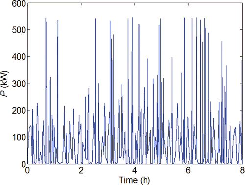
In this section, we first investigate the capability of finding a reference driving profile by our signal synthesis scheme. For that purpose, the driving profile of is taken as a case study. EAs are applied in association with each signal model (segment, sine and cardinal sine models) with the aim of minimizing the mean error ε between the reference and the generated profiles by the EA. This error can be defined as
(8)
where Pref and Pgen, respectively, represent the powers of the reference and generated profiles and N denotes the number of equally spaced sample points on the profiles (we take N = 863, i.e. one sample point per second).
3.2.1. Results with a fixed number of patterns
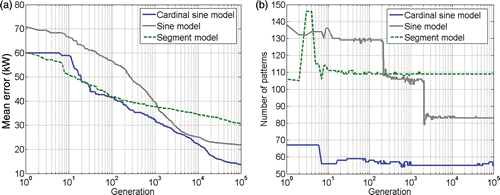
We first examine the efficiency of EAs for generating the reference profile of by considering a fixed number of patterns. We take n = 75 for the segment and sine models and n = 50 for the cardinal sine model, which leads to the same number of unknowns (i.e. 150) in the inverse problem. It should be noted that the mixing between different pattern types is not considered. The population size of each EA (ES, RTS and CL) is set to 100 and the generation number is G = 100,000. Five independent runs are performed for each combination (EA and signal model types). Best runs are illustrated in . In this figure, we plot for each EA and signal model the evolution of the mean error ε versus generations. It can be seen from this figure that CL outperforms ES and RTS in all cases. However, the mean error after 100,000 generations is still higher than 10 kW. We compare in , the profiles generated by CL with the reference driving profile of . It can be seen from this figure that results obtained with the segment and sine models are poor.
3.2.2. Results with a variable number of patterns
The a priori setting of the number of patterns is not straightforward. On the one hand, increasing the number of patterns increases the ‘inverse’ problem complexity by increasing the number of parameters that have to be identified by the EA. On the other hand, reducing the number of patterns does not to find signals with sufficient variability and diversity that are capable of representing real driving profiles. Therefore, we have proposed, in Section 2.2, a chromosome encoding strategy allowing the parallel investigation of signal configurations with different number of patterns. To assess the efficiency of this approach, we solve the same problem as previously with the same EA parameters. Results are illustrated in . We plot the evolution of the mean error and of the number of patterns during generations. It can be seen from this figure that results are not clearly improved in comparison with those obtained from a chromosome encoding with a fixed number of patterns. Nevertheless, it can be seen from that the algorithm tends to converge to higher number of patterns, i.e. 109 for the segment model instead of 75 stated in the previous section, 83 for the sine model instead of 75 and 53 for the cardinal sine model instead of 50. This obviously indicates the need of increasing the number of patterns to correctly identify the reference driving profile. On the other hand, the number of generations also has to be increased to converge to better solutions. Note that 5 days are required on a standard computer to find a solution after 100,000 generations. Consequently, the proposed approach is rather limited to accurately ‘reconstruct’ real driving profiles.
3.3. Generation of driving profiles from sizing and performance criteria
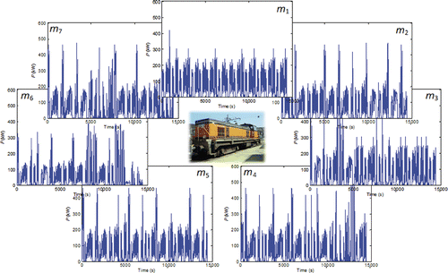
We now investigate the capability of our approach to represent a ‘fictitious’ driving profile that fulfills some design criterion. For that purpose, a set of seven railway driving profiles with same duration (i.e. 4 h) is considered (). The characteristics of these profiles with regard to the sizing and performance criteria defined in Section 3.1 are given in . Note that the useful energy Eu (column 3 of ) relative to the storage system is computed by considering the averaged power over all driving cycles (i.e. Pav = 70 kW). In effect, the power of the main supply Pav required to fulfil all driving cycles can be chosen in the following interval:
(9)
where i = 1…7 denotes the index of the driving profiles. This interval traduces the tradeoff between the main supply sizing and the auxiliary supply sizing. In order to reduce the size of the main supply, the minimum value of the interval has been taken, i.e. Pav = mean Pav(i) = 70 kW. Then, designing a hybrid electric system that fulfills all driving cycles requires setting the other sizing parameters to their critical values, i.e.:
(10)
(11)
Table 1. Set of seven driving profiles characterized with the sizing and performance criteria.
The values of the performance criteria computed from the seven profiles can be expressed as the averaged values over these profiles, i.e.:
(12)
It should be noted that contrary to Citation1, this number of cycles is expressed per unit of time (i.e. per hour) for allowing the comparison of cycling profiles with different lengths.
The CDF associated with all profiles is obtained by integrating the pdf computed from the concatenation of all driving profiles.
Finally, the global set of driving cycles of can be summarized by an equivalent fictitious profile with the sizing and performance criteria of .
Table 2. Sizing and performance criteria relative to an equivalent profile representative of the set of seven profiles.
We use our signal synthesis approach in order to find a ‘fictitious’ driving profile which represents the set of driving profiles. For that purpose, we defined the global error ε between the generated profile and a reference ‘fictitious’ one as follows:
(13)
where the statistic error εstat is defined as the mean-squared error, computed over 100 equally spaced points, between both CDFs relative to the power of the driving cycles:
(14)
The global error ε is minimized using CL in association with the segment model and with the chromosome strategy allowing a variable number of patterns. The population size is set to 100 and the number of generations is G = 20,000. The ‘fictitious’ driving profile obtained after the problem inversion is given in . We also give in the values of the sizing and performance criteria of this profile in comparison with the reference values. Results show that our signal synthesis approach performs well and is capable of easily finding a profile shape representing the whole set of driving profiles. It should be noted that the ‘fictitious’ profile duration is about 8 h. In comparison with the global duration of the seven profiles (i.e. 28 h), the profile duration has been reduced by 3.5. Consequently, in a design optimization process such as in Citation1, the simulation of any hybrid electric system will be reduced by the same factor.
Figure 10. ‘Fictitious’ driving profile generated by CL from 263 elementary segments with equivalent characteristics of the whole set of profiles.

Table 3. Comparison of sizing and performance criteria of the ‘fictitious’ driving profile generated by CL with the corresponding reference criteria representative of the whole set of driving profiles.
4. Conclusion
In this article, a signal synthesis approach has been proposed for generating signals with particular shapes. This approach consists of combining elementary patterns (segment, sine or cardinal sine) in order to fulfil several constraints related to the signal features. The characteristics of the patterns (amplitude, phase or duration) are optimized with an EA. An original chromosome encoding strategy has also been presented with the aim of determining the pattern parameters as well as the appropriate number of patterns. Our approach has been applied to the generation of driving profiles in the context of railway system design. On the one hand, the signal synthesis method has shown some limitations to correctly ‘reconstruct’ and represent a real’ driving cycle of the BB 63 000 locomotive, due to the important number of patterns required. On the other hand, it has been successfully applied to the simplification of a set of driving profiles. By fulfilling representative sizing and performance criteria issued from the analysis of the data set, the proposed method was capable of finding a ‘fictitious’ driving profile with the same features. Such an approach leads to an implicit reduction of the profile duration and consequently to the reduction of the computing time associated with the locomotive simulation in an optimization process. Finally, it should be noted that this approach could be extended for any hybrid electric vehicles. More generally, it could also be applied to represent and simplify any system environmental variables.
References
- Akli, CR, Sareni, B, Roboam, X, and Jeunesse, A, 2009. Integrated optimal design of a hybrid locomotive with multiobjective genetic algorithms, Int. J. Appl. Electromagnet. Mech. 4 (2009), p. 151−162.
- Jaafar, A, Sareni, B, and Roboam, X, , Clustering analysis of railway driving missions with niching genetic algorithms, 11th International Workshop on Optimization and Inverse Problems in Electromagnetism (OIPE’2010), Sofia, Bulgaria, 2010.
- Bracewell, R, 1999. The Fourier Transform and its applications. New York: McGraw-Hill; 1999.
- Schwefel, HP, 1995. Evolution and Optimum Seeking. New York: Wiley; 1995.
- Sareni, B, and Krähenbühl, L, 1998. Fitness sharing and niching methods revisited, IEEE Trans. Evol. Comput. 2 (1998), p. 97−106.
- Petrowski, A, , A clearing procedure as a niching method for genetic algorithms, IEEE International Conference on Evolutionary Computation, Nagoya, Japan, 1996.
- Harik, G, , Finding multimodal solutions using restricted tournament selection, 6th International Conference on Genetic Algorithms, San Francisco, CA, 1995.
- Nguyen-Huu, H, Sareni, B, Wurtz, F, Retière, N, and Roboam, X, , Comparison of self-adaptive evolutionary algorithms for multimodal optimization, 10th International Workshop on Optimization and Inverse Problems in Electromagnetism (OIPE’08), Ilmenau, Germany, 2008.
- Ehsani, M, Gao, Y, and Butler, K, 1999. Application of electrically peaking hybrid (ELPH) propulsion system to a full-size passenger car with simulated design verification, IEEE Trans. Veh. Technol. 48 (1999), pp. 1779–1787.
- Akli, CR, Roboam, X, Sareni, B, and Jeunesse, A, , Energy management and sizing of a hybrid locomotive, 12th European Conference on Power Electronics and Applications (EPE'2007), Aalborg, Denmark, 2007.
- Dufo-Lopez, R, and Bernal-Agustin, JL, 2008. Multi-objective design of PV–wind–diesel–hydrogen–battery systems, Renew. Energy 79 (2008), pp. 2559–2572.
- Baek, SH, Cho, SS, and Joo, WS, 2008. Fatigue life prediction based on the Rainflow cycle counting method for the end beam of a freight car bogie, Int. J. Auto. Technol, 9 (2008), pp. 95–101.
![Figure 2. Individual genotype according to the chromosome encoding strategy: (a) with fixed (n) and (b) variable (n ∈ [1, npmax]) number of patterns.](/cms/asset/795540ab-c0a2-41f2-83d5-2a6aa071d637/gipe_a_624619_f0002.gif)


