Abstract
This article presents a direct application of a Tikhonov inversion with a quadratic constraint applied in the case of a corrosion diagnosis. The main originality of this method is to inject physical information during the inversion to automatically restrict the Tikhonov parameter space. This application is then tested on a real case of corrosion diagnosis from electrical measurements in the water.
1. Introduction
During its operating life, an underwater steel structure needs to be protected from corrosion. With an adapted painting, an effective way to passivate defects is the cathodic protection. This system creates currents in the water circulating from anodes to cathodes and noble parts. This induces a varying electromagnetic field in the conducting media which can be measured and used to make a corrosion diagnosis of the structure. Such a diagnosis tool requires a modelling of the structural physical behaviour leading to a numerical system which is then inversed. This system is unfortunately often ill posed and different inversion techniques have been tested. Tikhonov method has been finally used, which provides good results in simulations. Some of them have been presented in another article Citation1 and we propose here to give a main improvement by constraining the Tikhonov parameter choice, thanks to an inequality constraint. After having described the case studied in forward modelling, the improved inverse method and some results are described. In the final part, some experimental achievements are presented.
2. Description of the case studied
To develop a diagnosis tool, first, an interest in modelling the electromagnetic field is necessary. It is called Forward modelling. The first part of this article deals with its matrix formulation and its use in inversion.
2.1. Green identity
Let us consider an underwater domain, where water is supposed to be linear, homogeneous and isotropic. Working in a static case, the electric potential ϕ distribution satisfies the Laplace's equation in the domain Ω:
(1)
Using Green's third identity, a general expression is obtained:
(2)
In this last equation, h is the solid angle seen by M0 and S(Ω) the whole surface of Ω with a normal vector n. This equation will be frequently used to build numerical methods of inversion. The normal derivative of the electric potential can be expressed with normal current density and domain conductivity σ.
(3)
2.2. Writing an interaction system
The two unknowns of Equation (2) are the electric potential and its normal derivative on the surface S. It is necessary to define those quantities in corrosion protection: to prevent an underwater structure from corrosion, two main methods exist, which are the Sacrificial Anode Cathodic Protection (adding of a less noble metal to be corroded instead of the one to be protected) and the Impressed Current Cathodic Protection (ICCP) Citation2. We will only focus on ICCP, in which currents are injected in the water through noble anodes (in platinum), placing cathodes in their passivation area. This is done by decreasing their electrochemical potential ϕM (depending on the current quantity injected) to a desired smaller value.
An important hypothesis admitted is the binary behaviour of the structure: its surface can only be painted or corroded. This is not completely realistic but physically admissible as a less corroded area behaves as a strongly corroded one. Three different boundary conditions are finally available for underwater structure:
| • | Anodic parts (further subscripted A) inject currents in the water. Current densities JA (and so ∂ϕA/∂n) are known. | ||||
| • | Cathodic parts (further subscripted C) are the polarizable paint defects of the structure. Their polarization law, linking JC (and so ∂ϕC/∂n) to ϕC is well known, but most of the time non-linear, which will further lead to numerical difficulties. This law can be expressed as ∂ϕC/∂n = f(ϕC − ϕM). | ||||
| • | Isolated parts (further subscripted I) which are not corroded and do not let current enter. Their current density is null and so is ∂ϕI/∂n. | ||||
A last remark concerns the evaluation of electrical potentials here: indeed, a reference has to be chosen. Potentials involved in Equation (5) are contained into the conductive media (water); so it is interesting to compare them towards the metallic one of cathodes ϕM (cathodic protection target). Moreover, a polarization law defines the relation of current densities crossing a cathode towards its potential gap between metal and water (ϕC − ϕM). Setting this common metallic cathodic potential ϕM as a reference is a good way to only keep ϕC as the cathodic potential unknown in the water. Final polarization laws represent ∂ϕC/∂n = f(ϕC) and often have such a shape ().
Figure 1. Typical polarization law of marine steel.
Equation (2) is too complicated to be analytically solved; so it is turned to a numerical one with a structure meshing into N surface elements. The behaviour of the both quantities introduced (ϕ and ∂ϕC/∂n) has to be defined on an element: a zero-order approximation is considered, meaning that ϕ and ∂ϕ/∂n are supposed to be constant per element. This hypothesis is not physically acceptable but will be further sufficient for a corrosion diagnosis. Moreover, those quantities will be expressed at the geometric centre of each element, and Equation (2) becomes (for the i-geometric centre Qi):
(4)
Finally, the global interaction system needs 2N integral computations and can be written Citation3:
with
(5)
This step of coefficients calculation, not described here for concision reasons, is made thanks to the well-known Gauss method (choosing an adapted Gauss points number to replace analytical integrals by steady sums). However, singularities occur when computing Hii and Tii (influence of an element on itself). In this case, rii and ni are always perpendicular: Hii is set null. To compute Tii, each triangle is divided into six right-angled triangles which have the geometric centre in common. An analytical formula exists to compute T at the geometric centre of the former triangle for each new triangle Citation4. The sum of those six new quantities is Tii.
2.3. Resolution and post-processing
Once System 5 is obtained, a resolution step has to be made to find the missing ϕA, ϕC, ∂ϕC/∂n and ϕI. As mentioned before, the main problem stands in the non-linearity of the polarization law linking ϕC and ∂ϕC/∂n. A Newton–Raphson iterative solver is used for its ease of both implementation and parameterization. Its residual norm R is composed of two quantities (based on BEM and Polarization law) and a varying parameter :
(6)
Finally, all ϕ and ∂ϕ/∂n are obtained on the whole surface of Ω with few iterations (five or six in most cases). A qualitative remark for corrosion diagnosis is that cathodic areas (paint defects) have the lowest potentials and positive current densities (as we have defined current injection with negative current densities).
Once all the boundary conditions have been computed, the electric potential is available everywhere in Ω with Equation (2). With the previous meshing, potential at an inner P point can be computed with 2N integrals:
(7)
This post-processing step is completely linear, avoiding the use of an iterative solver. It has to be kept in mind while building the inverse problem.
2.4. A simulation case
Let consider an application of the previous method, with a parallelepipedic and isolated bowl. An isolated mock-up is immerged at the centre bottom of the bowl, with two rectangular paint defects and one centred anode. Both the meshed bowl and mock-up are represented in .
Figure 2. Meshed bowl (a) and mock-up (b), with two green defects and one red anode.
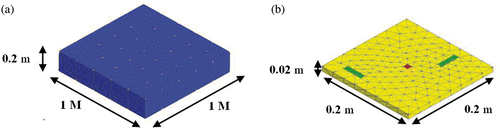
This example of meshing leads to 612 surface elements (2 anodic, 12 cathodic, 598 isolated). After building System 5, resolution step is run and the following boundary conditions are obtained (for σ = 0.1 S m−1, JA = 5 A m−2, non-linear polarization law) on the mock-up (with a residual norm precision fixed to 10−4, algorithm convergence in five iterations; ).
Figure 3. Boundary conditions obtained on the mock-up: potential in V (a) and current density in A m−2 (b).
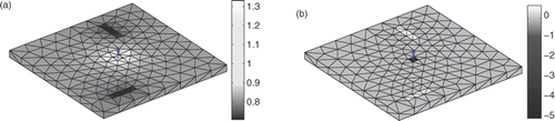
As mentioned before, corroded areas have the lowest potentials and highest positive current densities (from the definition of normal vectors). An important remark is that quantities considered here (polarization law, conductivity and current densities) have been chosen from real marine cases. Let us now consider a calculation grid in the water, near the mock-up, where 400 electric potentials will be computed. System 7 allows the computation of the electric potential on this grid.
Some additional contents about magnetic computation can be found in a previous communication Citation5. We have presented here a prediction method of the electric potential in the water from the knowledge of a part of boundary conditions (location of corroded parts, etc.). An interesting idea is now to develop an inverse method for the corrosion diagnosis of immerged structures under cathodic protection, from a set of electric measurements in the water.
3. Inverse method
3.1. Defining the problem
As mentioned before, the main interest of the inverse method is to find back the corrosion state of an underwater structure from a set of electrical measurements in the water. Remembering linear Equation (7), it consists, from a ϕm vector (all measurement quantities will further be subscripted m), of finding the boundary conditions vector X (ϕ and ∂ϕ/∂n) on the structure.
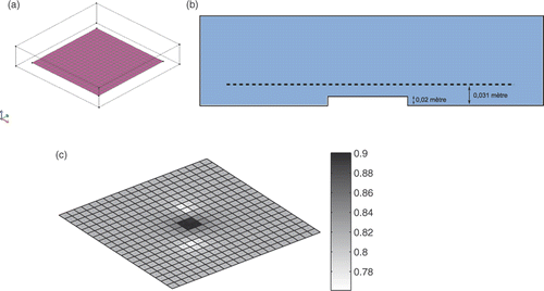
In this part, the study will be illustrated with the case presented in the previous paragraph. With the same structure (presented in ), the aim is, from measurements, to obtain boundary conditions of . As mentioned before, boundary conditions point out the corroded areas with lowest potentials and/or highest positive current densities. Three new surface regions are considered: an anodic one (again subscripted A), the bowl region (subscripted B) whose current density is null and the structure region (subscripted S) where the corroded areas are searched.
Figure 4. Calculation grid in the bowl (a) and transversal view of the bowl (b) and electric potential (V) (c).
Finally, this problem can be summarized with the following general system:
(8)
This problem is hard to solve because several difficulties are encountered:
| • | The only information we have on the structure is the current density injected in the water (and so ∂ϕA/∂n) which represents few clues about the state of the system. | ||||
| • | ϕm is a vector that contains measurement errors. | ||||
| • | Matrix Am is built from calculation of integral terms (Equation (10)), containing rounding errors. | ||||
| • | Vector X has two kinds of unknowns which are potentials and their normal derivative. They may not have the same range, which also interfere in the coefficient of A (the two kinds of integrals terms in Equation (7) will not have the same range, due to decreased rates at different orders: 1/r and 1/r2). | ||||
| • | Last but not least, the number of equations (that is to say measurements) and unknowns are in most of the cases different. A is rarely a square matrix, which leads to the main difficulty of this inverse problem. | ||||
Finally, when evaluating the condition number of System 8, it appears that we face a very ill-posed problem. To illustrate this, it is possible to solve the inverse problem with a direct method, like the Singular Value Decomposition (SVD) or minimization of the normal equation. The last one consists of:
(9)
It leads to a pseudo-solution X0 of the form:
(10)
From a finer meshing of the structure (1576 total unknowns) and 1600 measurements, the huge condition number obtained is about 1.48 × 10¹⁹. Inversing the problem gives the following boundary conditions ().
Figure 5. Boundary conditions obtained on the structure: potential in V (a) and current densities in A m−2 (b).
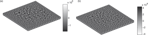
These results are mathematically right (it fits Equation (7)) but it is obvious that they are physically wrong, with huge range of values and no convenient behaviour. First, work has to be previously done on the system for avoiding this kind of results.
3.2. Adding equations
In the previous paragraph, we have presented the main reasons leading to inversion difficulties. We cannot do anything for most of those, such as measurement and calculation errors. But let us focus on the fourth one, concerning the two ranges of unknowns. Indeed, a direct inversion leads to a non-physical solution, especially because unknowns are not linked to each other, but only with measurements Citation6. One smart idea may be introducing the third Green equation system expressed in Equation (5), which is newly written here:
(11)
The new system to inverse is then:
(12)
This new writing has two main advantages: solution values further obtained may be huge but will fit the Laplace equation and so have a more correct physical behaviour. Moreover, the system can be simplified by removing one kind of unknown, which will be post-calculated thanks to a forward modelling. The current density injected in the water (∂ϕA/∂n) will be conserved as unknown, leading to the following system:
(13)
As we know the values of ∂ϕA/∂n and ∂ϕB/∂n (null), the final system becomes:
(14)
A numerical analysis of AmS may now impact the inversion process: As a defined set of measurements is the starting point of the inversion, it is possible to properly choose the structure meshing:
| • | From a structure with more meshing elements (and so unknowns) than equations (called underdetermined), we get a global diagnosis with local corrosion clues. It may be interesting to quickly check the state of an underwater structure. | ||||
| • | With more equations than unknowns (called over determined), a corrosion evaluation on each meshing element can be obtained. Accurate information, and especially gradient between meshing elements, can be obtained. | ||||
The objective is to locate corroded areas of a structure; so the second case will be considered in the following sections. Thus, the structure studied is meshed with fewer elements than measurements. Unfortunately, it algebraically leads to an infinite number of solutions. A proof of this is the condition number, which is not significantly better. This is also due to rounding in AmS computation and measurement approximations. A regularization technique has to be used to find an acceptable solution.
3.3. Choosing a regularization technique
Different regularization techniques exist, such as the Truncated SVD (TSVD) or recent non-linear regularization. However, in this study, the chosen one is the well-known Tikhonov regularization. It can be applied to different systems, depending on the information physically provided (a priori solution known, physical behaviour of the solution, etc.). In our case, a priori information about the physical behaviour of the solution can be guessed. Thus, two new quantities are introduced:
| • | A regularization matrix L representing the physical behaviour guessed on the further solution. It should be remarked that TSVD is a Tikhonov regularization taking L as the identity matrix. | ||||
| • | A regularization parameter λ settling the compromise between solution accuracy and regularization effect. | ||||
With these new parameters, regularization aims to minimize the following residual S term:
(15)
The new solution of the normal equation is the following:
(16)
It must be mentioned that Equation (16) is not exactly used to compute the solution: using deteriorates the condition number deeper. Using the Generalized SVD (decomposing AmS, B2 and L) does not affect the inversion. This new writing does not add visible information; so, it is not presented here for reasons regarding concision, but will be further used during numerical steps.
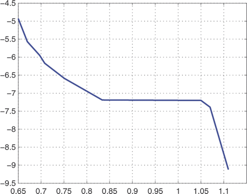
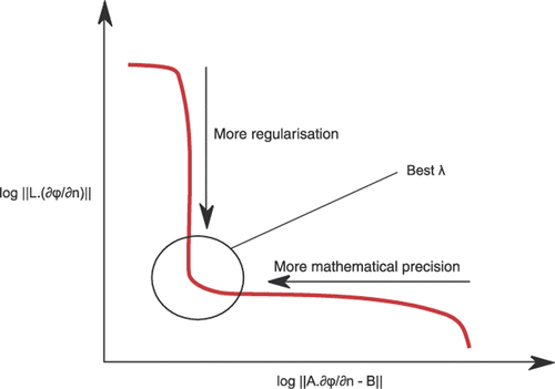
To summarize, Tikhonov technique consists of, from an L matrix choice, finding the best λ parameter, a compromise between solution precision (meaning mathematical precision) and preferred physical behaviour. One common way to evaluate this compromise is to draw the L-curve, representing residual norm towards regularization one for different λ values Citation7. Its name comes from the form it often has in this case ().
Figure 6. Example of an L-curve.
3.4. Choice of the L matrix
The first step of regularization concerns the L matrix choice, which is the representation of the preferred physical behaviour of the solution. Different kinds exist:
| • | Order 0: it is the identity matrix, whose dimension is the same as the number of unknowns. Minimizing the regularization norm gives the minimum norm solution. It is the basic one with lowest amplitudes. | ||||
| • | Order 1: this matrix helps in minimizing the difference of the solution gradient, that is to say the value difference between an element and its neighbour. | ||||
| • | Order 2: this time, it leads to the minimization if the Laplacian of the quantity on the meshing. | ||||
| • | Many other kinds of regularization matrixes could be imagined, etc. | ||||
First, let us have a look at those different kinds of matrixes; order 0 one appears the most fitted, especially because current density can vary much from one element to its neighbour. But when using this, many errors appear on the boundaries, like negative current densities (corresponding to injection ones). That is why an order 2 is preferred: some amplitude errors can occur but they globally smoothe the result. As the result required is more qualitative than quantitative (indeed, clues of corroded areas are positive current densities, ‘no matter’ the amplitude, etc.), it fits our philosophy more.
To build this matrix, it is first necessary to find all the neighbours of each element. Considering a p element with v neighbours, the corresponding row in the L matrix will be:
(17)
3.5. Application to the previous example
Let us use the previous example in simulation: We first consider the potential values of as entries. To fit more realistic cases, it is decided to add random noise to those values (up to 10% of the maximum value). Then, a realistic meshing is built without defect delimitation. The number of meshing elements must be carefully chosen to stay in an over-determined case (less M-elements than measurements). The new meshing contains:
| • | 2 Anodic elements. | ||||
| • | 372 Mock-up elements. | ||||
| • | 386 Bowl elements (not represented in ). Figure 7. Meshing of the mock-up (a) and noisy values for ϕm on the grid (b). 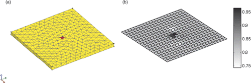 | ||||
Before inversing the system, it is important to discuss how results are analyzed. Indeed, quantitative results give clues about the mathematical aspects of the solution towards the expected one. But it can be difficult in those cases to clearly differentiate corroded areas. Actually, it is more interesting to strongly regularize solutions and obtain false amplitudes to see the cathodes better. That is why a qualitative observation is more relevant than a quantitative one.
When building System (14), 372 normal derivatives of potential are unknowns. Then, L matrix is built and the L-curve can be drawn. As we face a simulated case, L-curve has a quite ‘L’ shape and λ choice is made easier (5 × 10⁻⁴ is kept). For more visibility of the results, we decide to keep only the 50% upper values of positive current densities and the 5% lowest values of the potentials ().
Figure 8. L-Curve obtained (a) 50% upper positive current densities in A m−2 (b) and 5% lowest potentials in V (c).
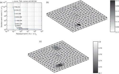
Comparing those results to the target ones of , we observe that the corroded areas are found back. As the meshing is no more adapted to the defects, those are not completely recovered. Let us see how it works with a more meshed structure and the creation of another set of 1296 measurements (1182 S-elements; ).
Figure 9. 50% upper positive current densities in A m−2 (a) and 5% lowest potentials in V (b) on a finer mesh.
With this new example, some errors appear during the diagnosis, illustrating the limit of refining too much of a meshing. Indeed, redundancy appears with too many measurements. A compromise between the concentration of meshing elements and precision (from the number of measurement to make) has to be considered. The main drawback of this method stands in the manual choice of the λ parameter, from numerical considerations (L-curve). One smart improvement shall consist of using more a priori information to avoid or constrain this choice.
4. Improving the method with constraints
4.1. Introduction of error estimation
We have seen in inverse problem definition that measurement and calculation errors lead to a degradation of the condition number. This first improvement deals with the estimation of those errors to constrain the λ parameter choice. Let us first consider the measurement error e on B2 vector. This error may be evaluated and defines a maximal measurement error parameter δe Citation8. Thus, residual norm can be upper bounded. New goal is now choosing λ, whose solution (∂ϕS/∂n)λ verifies the following equality:
(18)
To go deeper into this philosophy, we may take into account the calculation error δE of matrix AmS (depending on the precision of the computer, often negligible towards others). It also contains errors introduced by the use of a meshing and especially approximation hypothesis (zero-order and point matching approach). This leads to the new writing of the previous equation (subscripted exact mean solution without regularization):
(19)
Taking back the previous test case, random noise introduced is upper bounded by 10% of the maximum potential value (0.92 V), which has 0.1 V difference with the mean value (0.82 V). Finally, maximum noise introduced is 10 mV. This is really more than the recent computer precision and meshing approximation; so δE is negligible here. Finally, we come back to Equation (18). Having evaluated error e, δe, has now to be chosen. It induces a new problem: if we take λ from the equality in Equation (23) with δe = (m.e), the results are often too smoothed. Diagnosis fails, simply because random error cannot be estimated but drastically upper bounded. So, it is chosen to use δe only as an inequality constraint:
(20)
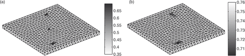
The λ choice is still manual but the space of solutions shall be reduced. Practically, this method is not much better than the previous one, as a too important search space remains for λ choice. Some tests with different λ values have to be done to observe the smoothing effect and precision level. With this method, we finally find λ leading to the following results on the fine meshed ().
Figure 10. Results with an error estimation: 50% upper positive current densities in A m−2 (a) and 5% lowest potentials in V (b).
Corroded areas are found but the λ choice, although easier, is still too difficult to make and has a part of random behaviour. Let us try to develop other tools with no error estimation.
4.2. Introduction without error estimation
4.2.1. General cross-validation
This method Citation9 allows us get to a solution without estimating the error. This is done by tracing a new curve illustrating the residual norm towards the matrix gap due to regularization. Let us write the regularized solution in this way which is a new one:
(21)
is the matrix modified due to regularization to get the same B2 vector. A new G function is then introduced:
(22)
The trace function is a sum of diagonal coefficients from A · A# matrix. Numerator represents the residual norm for the corresponding λ and denominator the matrix gap induced by this regularization. Finding the minimum of this function stands as the best compromise between mathematical precision and numerical divergence limitation. Once again, the General SVD is used, but here to introduce L matrix in the previous definition of G. In our case, the G-curve has the following form with corresponding results ().
Figure 11. G-curve with minimum for λ equal to 9.1 × 10⁻⁵ (a), 50% upper positive current densities in A m−2 (b) and 5% lowest potentials in V (c).
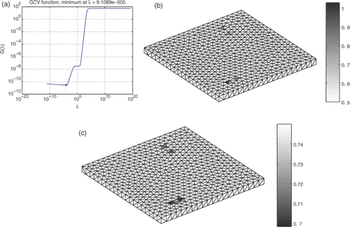
This method does not need a λ choice anymore and guarantees good results. Its only drawback is its sensitiveness to numerical approximation due to regularization. Practically, a solution obtained can leave a part of its physical definition, with great amplitudes for example. But once again, the aim of the diagnosis is more qualitative than quantitative; so this tool is very useful. Let us now try to inject more physical information to the λ search instead of doing numerical reasoning.
4.2.2. Least square quadratic inequality constraint
The main goal of this method is to drastically limit the λ search using physical information. This is done by finding α or β parameter to apply one of the two following least square quadratic inequality (LSQI) constraints:
(23)
(24)
Once one constraint has been chosen, the resolution process consists of searching the best λ parameter in the truncated L-curve. Numerically speaking, we observe both residual norms for a defined set of λ and take the one fitting most Equation (24). This may appear like an insufficient constraint but it works. Indeed, when choosing a smart α or β, the search is clearly restricted to few values of λ. Most of the results obtained with those λ give the same solution. The main advantage of the method with error estimation is the choice α or β, which is clearly defined.
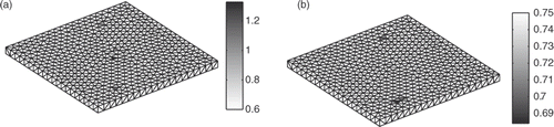
This article is based on Laplace equation and so on conservation of currents in the water. As we know the quantity of currents injected in the water, we also know the quantity expected to go back to the structure. Thus, it is possible to impose not only positive currents on the structure but also bound the sum of those currents. This works with Equation (23), taking an order 0 regularization and so an identity matrix for L. The quadratic norm of L multiplied by ∂ϕM/∂n is the sum of currents going back to the structure. The α coefficient is thus the sum of injected currents in the water. Empirically, we see that it can be interesting to relax the current's direction on each element and underestimate this parameter: this avoids a global smoothing of the diagnosis. From a reduction α equal to 50% of the currents injected, the following results are obtained ().
Figure 12. Results with a LSQI with α equal to 50% of the injected currents: 50% upper positive current densities in A m−2 (a) and 5% lowest potential in V (b).
This reduction of α gives a less regularized solution, which can be a little bit noisy instead of being smooth. But in all cases of tests, it works well to determine the corroded areas. The only necessity to assure best results is to do previous simulations to observe the sensibility solution towards α or β parameter. Without this, solutions obtained are precise enough but we often have to superpose current and potential diagnosis to find all the corroded areas. We can imagine other improvements like both using order 0 and 2 regularizations to avoid this final noisy behaviour.
The last two methods give good results with efficiency, regarding imprecise considerations made (graphical choice of λ, errors estimation), and it may be complicated to choose the best one. Actually, general cross validation (GCV) method is general and its accuracy depends only on numerical approximations. This method will be kept when no extra information can be taken from the physical context. On the other side, when having unused information about solution behaviour or residual norm, it is more interesting to use the LSQI. In general, this leads to same kind of results of the GCV with more physical values.
5. Experimental validation
5.1. Measurement bowl
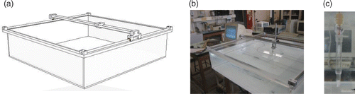
Throughout this article, a main example of underwater structure has been built, especially to test the inverse method and its improvements. This simple structure choice comes from a final wish of experimentally testing our algorithm in laboratory. Remembering the wish of a structure immerged in the centre bottom of finite volume of water, a parallelepipedic bowl is imagined. Its surface has to be an isolated part; so it will be made of PMMA (Plexiglas). To realize the electric potential measurements, a mobile system on two sets of rails is imagined, which can carry an electrochemical reference electrode. An illustration of this system is presented below ().
Figure 13. Bowl design (a), bowl realized in measurement stage (b), reference electrode (c).
5.2. Mock-up studied
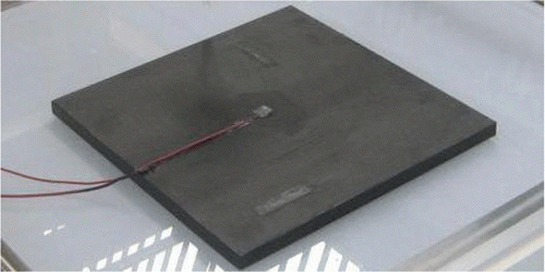
Then, an experimental structure is created, fitting the description made in the second part: a metallic plate (in common steel, 0.2 × 0.2 × 0.02 m3) is covered with an adapted painting, except two rectangular areas which simulate defects. This painting should be carefully chosen, as many of them are composed of zinc (to behave like a primary sacrificial cathodic protection), which does not isolate the structure with an ICCP. This last anodic protection is realized with a platinum mesh placed at the upper centre of the structure with an adapted welding for electric connection ().
Figure 14. Steel mock-up created with two rectangular defects and one anodic protection.
5.3. Performing measurements
To correctly realize the measurements, the conductive media has to be carefully chosen and controlled. In the previous parts, the conductivity σ has been set to 5.6 S m−1, which is a realistic case of seawater. Unfortunately, it makes the media too conductive and currents do not expand enough in the bowl to be correctly measured. As we used marine range of values, we have to make a scale modelling to better fit the bowl dimensions. Thus, a new conductivity σ = 0.1 S m−1 is set, which corresponds to a particular salinity. Abacuses exist to directly link salinity to conductivity at different temperatures. Checking the water temperature (15°C) leads us to use a 5 g L−1 one. This concentration avoids quick deposition of salt at the bottom side, which is a non-negligible advantage with regard to the stability of measurements.
Remembering that the aim of those measurements is to obtain a set of electric potentials on a grid in the water, the electrical scheme has to be considered. It can be easily done using a voltmeter whose positive side is directly linked to the reference electrode and the negative one to the steel mock-up. As mentioned in the definition of the interaction system, the metallic potential of cathodes is numerically set to zero, which corresponds to the way it is suited here.
Measurements are then done for a total injection of a 400 mA current, thanks to the platinum anode. Evaluation of the potential in the water stands in local variations around a meaning value, set by the electrochemical context (polarization law, conductivity and current density). The main problem is the small difference value between those potentials and the meaning one, leading to redundancy. We have to let a security gap between measurement points to distinguish the correct differences. Consequently, it is impossible to perform as many measurements as used in the last parts of this article. Finally, 400 measurements are made, following the position illustrated in . A last remark concerns the reaction kinetic, as electrochemical reactions do not instantaneously stabilize. A checking of injected currents permits the evaluation of this stability, which normally needs more or less 1 h.
5.4. Meshing used and inversion results
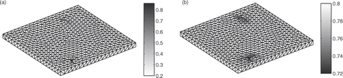
Having those measurements, the structure meshing used is also the one shown in , leading to primary 372 values unknown in ∂ϕM/∂n. The final system (14) is then built from the knowledge of all meshing positions. As anodic current is also set, it is possible to use the LSQI to perform the corrosion diagnosis on the structure. With the final definition of α parameter made in the previous part, the following inverse results of current densities and rebuild of potentials are obtained ().
Figure 15. Result of the experimental diagnosis: 50% upper positive current densities in A m−2 (a) and 5% lowest potentials in V (b).
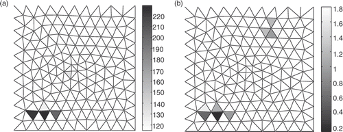
Considering only current density result helps us to find only one corroded area and it needs the study of the potential result for corroboration. In this way, the diagnosis succeeds in finding the corroded areas, with less accuracy due to the size of meshing elements. Those results are very encouraging as this laboratory sample experimentation is more numerically constrained than the real cases. Indeed, in Marine applications, for example, anodic currents are in the range of 10 V. Even in physical scale modelling, this represents much more than ones used in this part. Relevant space of measurements is increased and Marine sensors are at least as precise as the reference electrodes used. It seems reasonable to think that measurements on real structures could give interesting results.
6. Conclusions
This article has presented an efficient tool to complete a corrosion diagnosis of an underwater structure under cathodic protection, from electric potential in the conductor. It leads to a very ill-posed problem containing many unknowns and a huge condition number. But from a smart way of simplifying the system and using well-adapted regularization techniques, realistic clues about the position of corroded areas can be found. This interesting methodology is finally tested on a real case in laboratory, with very encouraging results. Many applications can be imagined, such as vessel hulls, pipe-lines, off-shore oil-platforms and off-shore wind power plants.
Some other improvements could further be done regarding the numerical methods used here. Using different orders for the potential evaluation on the meshing could improve the diagnosis from close measurements. Some other regularization matrixes could be imagined to improve the behaviour of the diagnosis solution. Those matrixes could also be used in parallel with the classical ones during the constraining step of the inversion. Finally, experimental tests have been found to be suitable only on small structures with a lack of relevant measuring space. Some new results obtained on more realistic mock-ups are being prepared for further communications.
As a conclusion, we would say that this study has been realized with a corrosion diagnosis goal. But it can be applied to any other kind of study where the Laplace equation is verified (thermic, bioelectricity, etc.). This needs adapted adjustments, but opens many ranges of work.
References
- Brebbia, JA, Telles, JCF, and Wrobel, LC, 1984. Boundary Elements Techniques, Theory and Applications in Engineering. Berlin: Springer-Verlag; 1984.
- Morgan, J, 1987. Cathodic Protection, . Houston, TX: National Association of Corrosion Engineers; 1987. p. 519.
- Zamani, NG, Chuang, JM, and Porter, JF, 1987. BEM simulation of cathodic protection systems employed in infinite electrolytes, Int. J. Numer. Meth. Eng. 24 (1987), pp. 605–620.
- Haghi-Ashtiani, B, , Méthodes d’assemblage rapide et de résolution itérative pour un solveur adaptatif en équations intégrales de frontières destiné à l’électromagnétisme, Ph.D., The Ecole Centrale de Lyon, 1998.
- Guibert, A, Coulomb, J-L, Chadebec, O, Rannou, C, and Nogueira, RP, 2009. Ships hull corrosion diagnosis from close measurements of electric potential in the water, IEEE Trans. Magn. 45 (3) (2009), pp. 1828–1831.
- Duthoit, FM, Krähenbühl, L, and Nicolas, A, 1985. The boundary integral equation method for the extrapolation of field measurement, IEEE Trans. Magn. MAG-21 (6) (1985), pp. 2439–2442.
- Hansen, PC, 1997. Rank-deficient and Discrete Ill-Posed Problems: Numerical Aspects of Linear Inversion (Monographs on Mathematical Modeling and Computation). Philadelphia: SIAM Editions; 1997.
- Golub, GH, Heath, MT, and Whaba, G, 1979. Generalized cross-validation as a method for choosing a good ridge parameter, Technometrics 21 (1979), pp. 215–223.
- Morozov, VA, 1966. On the solution of functional equations by the method of regularization, Soviet Math. Dokl. 7 (1966), pp. 414–417.