Abstract
Direct synthesis of recursive digital filters, whose characteristic function belongs to the new IIR filters class, is described in this article. Attenuation characteristic in the passband lies between the Butterworth's and the Elliptic's attenuation characteristics. All zeros of transfer function are placed on the unit circle so that the condition for complementary decomposition is fulfilled. Complementary decomposition into parallel connection of two allpass filters is performed. Then, lowpass filter is obtained summing these two filters and its complementary highpass filter – by their subtraction. The main advantage of this kind of filters is its smaller sensitivity to digital word length change compared to standard filters.
1. Introduction
During the last two decades, power symmetric filter banks have been used in sub-band of speech signals, image processing, multirate signal processing, wavelets and transmultiplexers. Originally, the concept of power symmetric filter banks is introduced for removing aliasing distortion in speech coding. Many design algorithms have been developed to obtain perfect or nearly perfect reconstruction filter banks. Most of these techniques focus on the design of the FIR filter bank that does not suffer from instability and phase distortion Citation1–4. However, the resulting filters require a large number of coefficients to meet the magnitude specifications. It is well known that from the aspect of decreasing the number of coefficients, the IIR filter bank is more efficient. Designing an IIR filter that has to meet both magnitude and phase specifications simultaneously is generally difficult Citation5–13.
Complementary decomposition, among known filters, has been possible only for the Butterworth and the Elliptic filters since only attenuation characteristics with the same number of extrema in the passband and in the stopband can be used. Direct synthesis of a new IIR filter class, whose attenuation characteristic lies in the area between the Butterworth's and the Elliptic's attenuation characteristics of the same order, is proposed in this article. All poles of the new transfer function are on the imaginary axis and all zeros are on the unit circle. This function satisfies all complementary decomposition conditions and condition for the removal of aliasing distortion.
Determination of the coefficients of digital lowpass and highpass transfer functions, which form power symmetric filter pair, has been formulated as inverse problem and carried out by the following procedures.
Squared magnitude function, with two extrema in both the passband and the stopband, generated by the new IIR filter design, is presented. Numerical procedure for the determination of extremal values of attenuation characteristics, in aim to make it equiripple in both the passband and the stopband, is performed in analogue domain (according to given value of minimum stopband attenuation).
Using appropriate frequency variable, this analogue square transfer function is mapped into digital domain. As a result, lowpass transfer function with all poles on the imaginary axis and all zeros on the unit circle in the z plane is obtained. Only poles that lie inside the unit circle are adopted and digital transfer function is obtained. This function is separated into two allpass filters by complementary decomposition. Finally, lowpass and highpass filters, as power symmetric filter pair, are obtained using those allpass filters.
2. Approximation
The IIR filter squared magnitude function can be specified by
(1)
where KN(x) is the characteristic function and x is frequency variable. At the passband edge it is K(1) = 1.
The proposed characteristic function, which defines the new IIR filter class, is given by
(2)
where N = M + 2L is the filter order, x0i are zeros of transfer function and real numbers (x0i < 1). Note that for L = 0 and M > 1, proposed characteristic function gives the Butterworth's polynomial. Furthermore, for L > 1 and M = 0 or M = 1, the result is the Elliptic function of even and odd order, respectively. New class of filters suitable for complementary decomposition is obtained for values L ≥ 1 and M > 1 and it will be referred to as Transitional Butter–Elliptic filters.
If x is analogue angular frequency x = Ω, then function (1) is the magnitude characteristic of the analogue lowpass transfer function. On the other hand, there are three possibilities for frequency variable x to obtain digital lowpass transfer function
(3)
(4)
and
(5)
where ωT is digital angular frequency and ωp is 3 dB passband edge. Equation (3) leads to transfer function with multiple zero at the origin, which is not suitable for complementary decomposition. Equations (4) and (5) lead to lowpass transfer function with multiple zero at z = −1 (ωT = π). However, Equation (5) gives transfer function that is inferior in comparison to Equation (4).
A two-channel filter bank consists of the analysis and synthesis bank as well as the signal processing unit between these two banks. It is well known that for the aliasing free reconstruction, the filter bank should satisfy the following condition in z domain Citation5:
where H0(z), H1(z) are analysis filters and G0(z), G1(z) are synthesis filters that have to be chosen as: G0(z) = H1(−z) and G1(z) = −H0(−z) in order to completely eliminate aliasing errors.
In order to obtain complementary filter pair, [H0(z), H1(z)], necessary and sufficient conditions that have to be fulfilled Citation12 are:
| a. | Power-symmetry condition, H0(z)H0(z−1) + H1(z)H1(z−1) = 1, where H0(z) is lowpass filter and H1(z) = H0(−z) is its complementary highpass filter. | ||||
| b. | Poles of power symmetric filters are restricted to be pure imaginary, | ||||
| c. | Zeros of power symmetric filters are on the unit circle. | ||||
According to conditions described above, frequency variable given by Equation (4) is the only acceptable one. Thus, for the new filter class design, frequency variable for lowpass filters synthesis is
(6)
with z = ejωT and tan(ωpT/2) = 1, since for half-band filter ωp = 2πFs/4 where Fs is the sampling frequency.
In order to perform complementary decomposition, transfer functions H0(z) and H1(z) are separated into two allpass filters, A0(z) and A1(z), as follows:
(7)
and
(8)
Therefore, it is necessary to determine the transfer function based on known squared magnitude characteristics on the unit circle (1). Known parameters of function (1) are: degree of flatness at the origin, M, number of ripples in the passband (stopband), L, and minimum stopband attenuation, Rs. Solution of this inverse problem are the coefficients bi and ai of the lowpass transfer function
(9)
The coefficients of the highpass transfer function, H1(z), has the same values except in numerator, where odd coefficients has the opposite sign.
Allpass filter coefficients for the odd filter order are real but for the even filter order are complex and therefore realization is harder for the even filter order. Only odd transfer functions will be considered below.
3. New class for L=2 and M > 1
The proposed characteristic function, with two ripples in the passband (stopband) and arbitrary degree of flatness at the origin, which defines new IIR filter class, is given by
(10)
where N = M + 4 is the filter order, x01 and x02 are zeros of the transfer function and both are real numbers (x01 < x02 < 1).
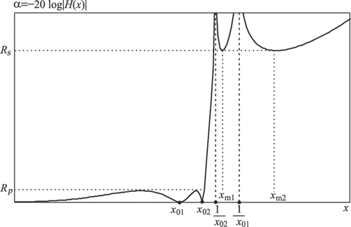
To make complementary decomposition possible, the attenuation characteristic should be adjusted to be equiripple, as it is shown in , i.e. values x01 and x02 should be calculated in reference to the given minimum stopband attenuation Rs. The unknown vector x = [x01, x02, xm1, xm2]T is determined using the Newton–Raphson method for solving the system of four nonlinear equations.
Figure 1. Attenuation characteristic of the transfer function with two extrema in both the passband and the stopband.

The first step is to determine the initial values of vector x, x0 = [x01, x02, xm1, xm2]T, which satisfy condition 1 < 1/x02 < xm1 < 1/x01 < xm2 < ∞ (e.g. x0 = [0.7, 0.9, 1.2, 1.7]T).
The set of four nonlinear equations can be expressed as F(x) = 0, where
(11)
and they have to be solved using an iterative procedure. The Newton–Raphson method has been used for solving these equations. The relations between the current values of x, x(i), and the new values of x obtained after one iteration, x(i + 1), may be expressed in the matrix form xi+1 = xi − λJ−1F(xi), i.e.
(12)
where J represents the Jacobian matrix and λ ∈ (0, 1] is the parameter which improves solution convergence. At the beginning of iterative procedure, a value of λ should be set at λ = 0.1. When condition max{ fj(i)} ≤ ϵ is fulfilled (ϵ is very small number, e.g. 10−4), λ = 1 is adopted.
This procedure can be simplified in terms of avoiding the second derivations which appear in Jacobian matrix for functions f3 and f4. At the same time, the number of nonlinear equations, which have to be solved by the Newton–Raphson method, is reduced to L. Now, for L = 2, the problem can be solved using the following steps:
| 1. | Set the initial conditions x0 = [x01, x02]T. | ||||
| 2. | Determine the values xm1 and xm2 as zeros of symmetric polynomial P(x) in numerator of rational function, obtained from the first derivation of characteristic function:
| ||||
| 3. | If the condition | f1| + | f2| < ϵ is satisfied, the above values for x01, x02, xm1 and xm2 are final and this is the end of numerical calculation. If not, go to next step. | ||||
| 4. | Obtain the new values of x01 and x02 using the Newton–Raphson method for solving the set of nonlinear equations:
| ||||
As a result of this numerical procedure, the obtained attenuation characteristic α = −20 log|H0(x)| is equiripple in both the passband and the stopband. If minimum stopband attenuation, Rs, is achieved then maximum passband attenuation is .
Next step is calculation of poles and zeros, in the z plane, of the squared magnitude function (1) using Equation (6), which gives digital squared magnitude function with all poles on the imaginary axis. By adoption poles inside the unit circle digital lowpass transfer function, H0(z) is obtained. Using complementary decomposition (Equations (7) and (8)), this transfer function is separated into two allpass filters. Then, lowpass filter is obtained summing these two filters and its complementary highpass filter – by their subtraction. Numerator coefficients of those power symmetric transfer functions are labelled as bi and denominator coefficients as ai.
4. Results of approximation
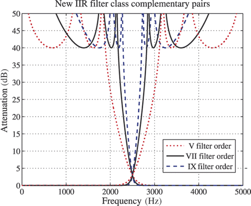
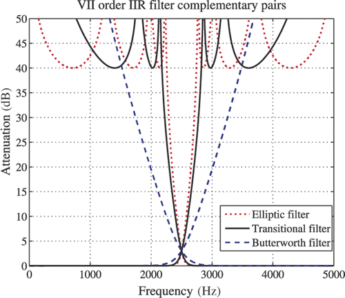
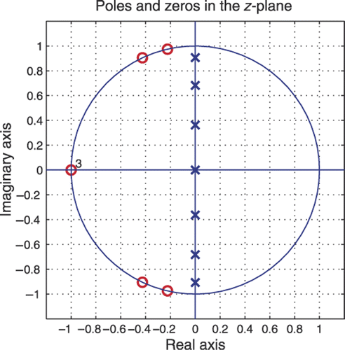
Complementary pair attenuation characteristics for the fifth, the seventh and the ninth order new class filters are shown in , where minimum stopband attenuation is Rs = 40 dB. Sampling frequency is Fs = 10 kHz and attenuation is 3 dB at the half of the frequency band fs = Fs/4. shows the Transitional filter complementary pair of the seventh order compared to the Butterworth's and the Elliptic's complementary pairs of the same order. Poles and zeros arrangement of the seventh order Transitional filter, for values M = 3 and L = 2, is shown in . Poles are located on the imaginary axis and zeros on the unit circle since passband frequency is equal to half of the frequency range.
Figure 2. Complementary pair attenuation characteristics for the fifth-, seventh- and ninth-order new class filters.

Figure 3. New IIR filter complementary pair attenuation characteristics for the seventh order compared to the Butterworth and the Elliptic filter of the same order for Rs = 40 dB.

Transfer function coefficients for the fifth, the seventh and the ninth order lowpass new class filters, are given in .
Table 1. Transfer function coefficients for the fifth-, seventh- and ninth-order lowpass new class filters.
In comparison with Butterworth filter, the Transitional filter has better selectivity but lower selectivity than Elliptic filter (). However, since Elliptic filter is designed using the bilinear transformation, its poles are not pure imaginary and their real part increases with the filter order. This results in error in highpass filter amplitude characteristic. This means that the Elliptic filter cannot achieve high accuracy in complementary allpass filter decomposition. The advantage of proposed new filter class is that it has pure imaginary poles and the accuracy in complementary decomposition is much higher.
5. Conclusion
Complementary decomposition has been possible only using transformation variable for the Butterworth and the Elliptic filter. In this article, synthesis of a new Transitional IIR filter without transformation variable, whose attenuation characteristic lies in the area between the Butterworth's and the Elliptic's attenuation characteristics, is presented. The new class filter has somewhat better properties in comparison with the Elliptic and the Butterworth filters.
Complementary decomposition procedure for transfer functions with two simple complex zeros on the unit circle and multiple zero at z = −1 is described. Those transfer functions have two oscillations in both the passband and the stopband. It is possible to form complementary decomposition for transfer functions with more oscillations, but it is necessary to fulfil condition that the number of oscillations in the passband and in the stopband is equal.
The advantages of the new class filter are the following:
| a. | The proposed new filter class has pure imaginary poles and accuracy in complementary decomposition is at very high level, which the Elliptic filter cannot achieve. | ||||
| b. | The practical realization of the new class filter is easier than for the Elliptic filter since the new class has two pairs of conjugate-complex zeros on the unit circle and one multiple zero at z = −1. | ||||
| c. | Poles and zeros of the Elliptic filter are accumulated near the passband edge and the distance between them decreases as the filter order increases. This requires a very long digital word length for high-order filter realization. The new class filter has approximately equidistant arrangement of poles so it can be realized with shorter digital word length than it is required in the Elliptic filter realization. | ||||
| d. | The new class filter has better stability since poles lie closer to the origin. | ||||
References
- Jou, YD, 2007. Design of two-channel linear-phase quadrature mirror filter banks based on neural networks, Signal Proc. 87 (2007), pp. 1031–1044.
- Kumar, A, Singh, GK, and Anand, RS, 2009. Design of quadrature mirror filter bank using particle swarm optimization (PSO), Int. J. Recent Trends Eng. 1 (2009), pp. 213–217.
- Kumar, A, Singh, GK, and Anand, RS, 2008. Near perfect reconstruction quadrature mirror filter, World Acad. Sci. Eng. Technol. 37 (2008), pp. 204–207.
- Park, SY, and Cho, NI, 2006. Design of signed Powers-of two coefficient perfect reconstruction QM bank using CORDIC Algorithms, IEEE Trans. Circuits Syst. I 53 (2006), pp. 1254–1265.
- Vaidyanathan, P, and Regalia, SMP, 1987. Design of doubly-complementary IIR digital filters using a single complex allpass filter with multirate applications, IEEE Trans. Circuits Syst. 34 (1987), pp. 378–389.
- Galand, CR, and Nussbaumer, HJ, 1984. New quadrature mirror filter structures, IEEE Trans. Acoustics, Speech, Signal Process. 32 (1984), pp. 522–531.
- Regalia, P, and Mitra, S, 1987. Tree-structured complementary filter banks using all-pass sections, IEEE Trans. Circuits Syst. 34 (1987), pp. 1470–1484.
- Selesnick, I, 1999. Low-pass filters realizable as all-pass sums: Design via a new flat delay filter, IEEE Trans. Circuits Syst. II Analog Digital Signal Process. 46 (1999), pp. 40–50.
- Milić, L, and Saramaki, T, 2003. Power-complementary IIR filter pairs with an adjustable crossover frequency, Facta Univ. Elec. Energ. 16 (2003), pp. 295–304.
- Zhang, X, and Amaratunga, K, 2002. Closed form of maximally flat IIR half-band filters, IEEE Trans. Circuits Syst. II, Analog Digital Signal Process. 49 (2002), pp. 409–417.
- Stojanović, VS, and Nikolić, S, 1998. Direct design of sharp cutoff low-pass recursive digital filters, Int. J. Electr. 85 (1998), pp. 589–596.
- Vaidyanathan, P, 2007. "Some properties of IIR power-symmetric filters". In: in ICASSP 2007. Vol. III. Hawaii, USA: Honolulu; 2007. pp. 1449–1452.
- Shpak, DJ, and Losada, R, 2002. IIRGRP delay in MATLAB Filter Design Toolbox. Natick, MA: The Mathworks, Inc.; 2002.
