Abstract
Thin platinum resistance thermometers (herein called thin film sensors) are often used in applications where rapid measurements of surface temperature are required. These gauges are typically vapour-deposited onto a non-conducting substrate surface and electrically connected with small wires through access holes to the surface. The time response of the gauge is measured in milliseconds and surface temperature data obtained with this gauge are often combined with a pseudo-inverse heat conduction algorithm to provide information about the surface heat flux. However, the thermal mass of the connecting wires, though small in absolute terms, is large compared to that of the thin film, and the capacitive effect of this mass gives rise to distortions in the temperature field in the area of the gauge, resulting in a small error in the sensed temperature. This temperature error, when used in the inversion for heat flux, also results in an error. In this article, a detailed model of a particular thin film gauge is used to compute the response of the sensor to supposed heating conditions. The response of the sensor and the undisturbed surface temperature are compared to estimate the temperature error. The effect of thermal contact resistance in the model is investigated. Finally, the error in the computed heat flux is determined. A simple technique based on superposition is applied to reduce the error in the estimated heat flux.
1. Introduction
It is well established that thermocouples embedded within a low-conductivity material give rise to distortions in the temperature field surrounding the junction Citation1–10. This distortion of the temperature field ultimately results in a temperature bias error. Typically, this bias error results in a sensed temperature lower than the temperature of the surroundings. This is because the presence of the high conductivity thermocouple lead wires offers a preferential path for heat removal from the bead and cooling of the region around the bead.
Most recently, Woolley Citation10, conducted a comprehensive investigation into temperature measurement errors through high-fidelity modelling of thermocouple installations. His findings affirm the previously reported results Citation1–3 for thermocouples mounted perpendicular to the heated surface. However, he also demonstrated that temperature field distortion and measurement error will also occur when thermocouples are installed parallel to the heated surface, although this effect is considerably smaller than for the perpendicular case.
What is less established is the effect of instrumentation on other types of contact temperature measurements: RTDs, thermistors, etc. Since these types of instrumentations also rely on metallic conductor wires for transmitting signals to a recording or readout device, it is reasonable to presume that these devices might also be subject to bias errors.
In this article, the results of a numerical investigation into the possible temperature field disturbance associated with a specific thin film thermometer design and installation are reported. The numerical model details are presented in the next section, followed by the results of computation to determine the temperature field in the region surrounding the sensor when excited by a constant heat flux history. Further computations are performed using a triangular time-varying heat flux, and the bias error is evaluated from these simulations. The effect of an interfacial contact resistance on the wiring installation is investigated and it is shown that increased resistance results in lower temperature bias. A ‘pseudo-inverse’ heat conduction solution is used to determine the heat flux using these biased results, both without and with simulated noise. Finally, a simple approach to improve the heat flux estimates by utilizing the detailed computational model to generate sensitivity coefficients is demonstrated.
2. Sensor model
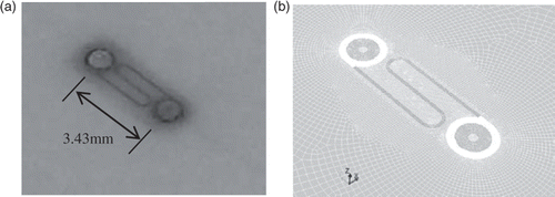
A photograph of the subject thin film sensor is shown in and its corresponding mesh model is in . The serpentine conductor between the two circular connections is actually the thin film of platinum, which was vapour-deposited and laser-etched on the surface. The body of the object on which the sensor is mounted is Macor and is about 6.35 mm (0.25 inch) thick. The material filling the main portion of the circular connecting post regions is silver epoxy which gives electrical continuity between the platinum film and copper wires beneath the surface. Note that the scale of the sensor is small with an overall length dimension of about 4.6 mm (0.180 inch) and the distance between centrelines of the connections is about 3.43 mm (0.135 inch).
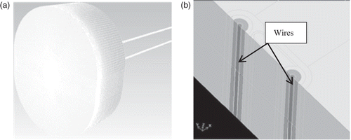
A numerical model of the sensor was created by isolating the sensor from the surroundings on a small plug of Macor, as illustrated in . This plug is about 25 mm (1 inch) long and 19 mm (0.75 inch) wide and about 6.35 mm (0.25 inch) thick. This isolation entails the assumption that the heat flow into the surface far away from the sensor is strictly one-dimensional, and therefore, the boundary along the edge of the ‘plug’ is adiabatic. Also shown in are the copper lead wire models which are connected to the thin film sensor via drilled holes in the Macor and the silver epoxy potting material. These wires are about 0.127 mm (0.005 inch) in diameter, and are seen in a cross-sectional view in . The surrounding grey material in is the silver epoxy.
It should be noted that in the base case considered, perfect thermal contact between all interfaces was assumed. Later, the effect of thermal contact resistance between the parent Macor material and the silver epoxy filling will be considered.
In the discussion that follows, reference will be made to the ‘sensor’ or ‘measured’ temperature and also the ‘undisturbed’ or ‘actual’ temperature. The sensor/measured temperature will be determined from the model output by calculating the average temperature of all the platinum thin film elements on the surface that connect the two wire posts together. This is readily obtained from the software by defining the collection of platinum thin film elements as a ‘surface’ and obtaining as an output the time history of the average temperature of that surface. The undisturbed/actual temperature is the temperature of the parent Macor material far away from the sensor. This was taken as the temperature of an element located at an arbitrary distance inside the far boundary of the Macor plug.
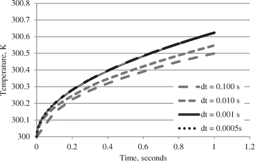
An initial grid with about 1.7 million calculation volumes was used and an integration time refinement study performed. The grid density was then increased to about 3 million volumes and integration time refinement performed. shows the temperature response at the undisturbed location (far from the sensor) for four different time steps. There is virtually no difference between the solutions for dt = 0.001 s and dt = 0.0005 s. For these two different time steps, the difference in the sensor response was 0.036 K. Thus, it was determined that an integration time step of 0.001 s was sufficient to limit discrepancies to 0.04 K and this time step was employed for subsequent calculations.
3. Demonstration of temperature bias
To demonstrate the bias error, a constant heat flux of 1000 W m−2 was imposed on the top surface of the Macor plug. All other surfaces were treated as adiabatic. As mentioned previously, the sensor temperature is taken as the volume-averaged temperature along the length of the serpentine platinum wires since the actual sensor temperature corresponds to the average resistance of the thin film on the substrate.
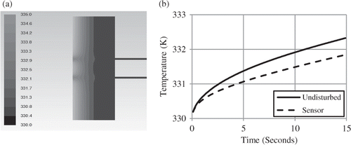
The source of the bias error can be seen in the centreline cross-section temperature contours of . The depression in the temperature field on the surface in the area of the connection terminals can clearly be seen.
The evolution of this bias error over time can be found by comparing the sensed temperature to that of the ‘undisturbed’. The undisturbed temperature was extracted from the numerical model by tracking the temperature of the surface of the Macor at a point near the edge of the plug. The sensed and the undisturbed temperatures are shown in for 15 s heating with a 1000 W m−2 heat flux. Note that the error at the end of the heating is about 0.5 K.
4. Effect of bias on the inverse solution
The determination of surface heat fluxes from measured surface temperatures is often called a ‘pseudo-inverse’ problem. This is because the temperature field in the body can, theoretically, be determined using the measured temperature of the surface as a boundary condition. The heat flux into the domain can then be found from the temperature field using the Fourier Law. Nevertheless, inverse methods, such as Beck's sequential function specification method Citation11 can be used to invert the measured surface temperature to obtain the surface heat flux. Use of an inverse method offers the possibility to regularize the solution to combat noise in the measured surface temperatures.
Beck's method is well documented in literature Citation11, but a brief derivation is given here. Beck's method is based on a convolution integral representation of the solution for T(x, t) as
(1)
where ϕ(x, t) is the solution kernel which represents the response of the domain to a step change in q at the surface.
The classic Beck's method is obtained by considering discrete time intervals t = iΔt, i = 1, 2, … , N. The simplest representation results when the function q(t) is considered piece-wise constant. That is, q(iΔt) = q1, q2, … , qN, for i = 1, … , N. Under these assumptions, the temperature at a particular location xj can be expressed as follows using the second expression of Equation (1)
The notation can be compacted significantly by introducing the familiar shorthand
Then
(2)
Suppose that all heat flux components up to time tM−1 have been estimated, and that qM is to be estimated using measurements YM, YM+1, … , YM+r−1.
(3)
The idea is to minimize the squared error between the expressions in Equation (3) and the measurements
Note that the last term is independent of the unknown heat flux components; so, a shorthand notation can be introduced
and the sum of squares becomes
Beck's method introduces stabilization (regularization) at the expense of bias in the solution by making the assumption that the unknown heat flux components are all the same over the r time steps
Then, the summation becomes
By minimizing this expression with respect to the single unknown heat flux, qM, the classic Beck's formula results.
Note that
So, the summation is reduced and the expression is
Solving for qM
(4)
Complete details of the method used can be found in Beck et al. Citation11.
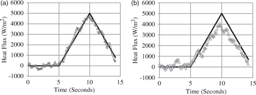
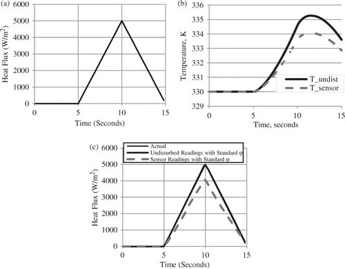
A triangular heat flux pulse, illustrated in , was used as input to the Macor plug and sensor. From this computation, the sensed and the undisturbed temperature histories were extracted and are depicted in . These temperatures were used directly as an input to solve the corresponding IHCP using Beck's method, and the results are seen in . The upper heavy black line is the result of estimation using the undisturbed data, while the lower light dashed line is that of the sensed temperature data. Note that the upper curve overlays the imposed (exact) heat flux, while the lower one under-predicts the heat flux by about 20% at the peak.
Figure 5. (a) Imposed heat flux; (b) recovered simulated data for undisturbed (upper) and sensor (lower) temperatures; and (c) recovered heat fluxes (errorless data).
To demonstrate the effect of noise on the data to the solution of the pseudo-inverse problem, random noise in the range of ±0.5 K was added to both the sensed and undisturbed temperature histories. These simulated measurements were then used as an input to Beck's method. The results, obtained with a value of r = 8, are seen in . shows the recovered heat flux if the ‘undisturbed’ temperature with noise is used as data and the result if the sensed temperature with noise is used. Note that a level of random noise (±0.5 K), which is slightly higher than what might be obtained in a well-designed experiment, causes significant excursions in the heat flux predictions. This is a manifestation of the inverse nature of the problem, even though data are obtained at the surface of the heat disturbance. Use of an inverse solver allows some smoothing of the solution through regularization of the problem.
5. Effect of thermal contact resistance
The sensor model just presented assumed perfect thermal contact between all materials in the sensor. This is very reasonable for some cases, for example, for the case of thin film sputtered on the substrate; however, the interfacial condition between the silver epoxy filling the holes with the walls of the Macor is unknown. Computations were performed to investigate the potential significance of this parameter.
Contact resistance was simulated by inserting a thin conductive layer with conductivity the same as air between the silver epoxy filler and the Macor. The first two rows of lists the textbook values for contact resistance between metals indicating a range of about 3E–4 to 25E–4 m2 K W−1. The last two rows show the resulting theoretical contact resistances of simulated conduction air gaps in the model for two thicknesses of air gap. Note that these two values are slightly higher than the corresponding entries in the first two rows.
Table 1. Contact resistances.
shows the results obtained from the simulation of thermal contact resistance between the epoxy and Macor. In , the sensor temperature histories for the three cases (perfect contact, low resistance, high resistance; these are the lower curves) are shown along with the ‘undisturbed’ response (upper curve). Note that the effect of the contact resistance is to isolate or insulate the parent domain from the unwanted effects of the copper wires. In other words, the contact resistance is favourable and helps the average temperature of the thin film to more closely track the temperature of the surrounding Macor.
Figure 7. (a) Resulting temperatures with thermal contact resistance and (b) heat fluxes computed with temperature histories using ‘undisturbed’ sensitivity.
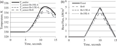
shows the heat fluxes obtained from the inverse solution using the simulated measurements in the case of thermal contact resistance. Not surprisingly, the closer the sensor temperature tracks the true surface temperature (‘undisturbed’), which is the case for higher interfacial heat transfer coefficients, the better the heat flux estimates.
6. Improved estimates through sensor modelling
The IHCP solution can be substantially improved if an accurate detailed model of the sensor dynamics is available. The sensitivity coefficients, ϕi, in Equation (1) can be computed from the detailed model by imposing a constant heat flux and monitoring the sensor output. This numerical technique for determining the ϕ function can be combined with the traditional Beck's method of Equation (1) to obtain much improved estimates.
shows the sensitivity functions obtained from the numerical model. The upper heavy line is the ‘undisturbed’ sensitivity function and corresponds to the ϕ function used for all the preceding IHCP solutions in this article. The lower light dashed line shows the temperature rise of the sensor due to a 1000 W m−2 heat flux imposed on the surface. When this latter ϕ is used as the sensitivity function in the IHCP and noised data from the thin film sensor are used, the heat fluxes in are obtained. These results are dramatically improved over the previous estimates using the sensed data (cf. ).
Figure 8. (a) Sensitivity coefficient functions and (b) results with noised sensor data using sensor sensitivity.
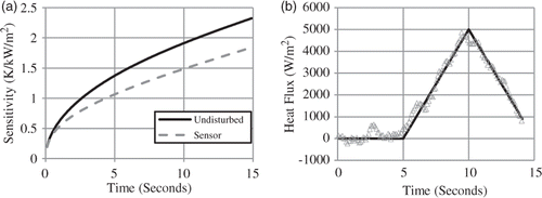
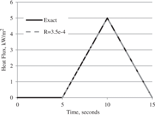
The use of the sensor model to improve estimates can, of course, also be applied to the model with contact resistance. The noiseless data from were used in Beck's procedure using sensitivity coefficients derived from numerical solution of the sensor subjected to a uniform heat flux of 1000 W m−2. Sensitivity coefficients were computed for the low resistance case and these were used in Beck's method to estimate the heat flux using the simulated data. The results are shown in . Note the dramatic improvement (cf. Figure 7(b)), as the exact and recovered heat fluxes are indistinguishable.
7. Conclusions
The presence of lead wires in a low conductivity domain may result in temperature disturbances in the regions of interest, leading to biased temperature readings. Use of these biased temperatures in the IHCP can, owing to the inverse nature of the problem, result in large errors (∼20%) in the estimated heat flux. Even if the problem is pseudo-inverse, and noise is present in the data, the regularization in an IHCP solution will help smooth the solution. For the thin film gauges studied in this article, the presence of a contact resistance between the silver epoxy filler and the parent material isolates the thin film sensor from the unwanted distortion of the temperature field due to the instrumentation. Detailed sensor modelling can be used to determine sensitivity coefficients that take account of the biasing sensor dynamics. Incorporation of these more accurate sensitivity coefficients in the solution results in a dramatic improvement in the estimated heat flux history.
References
- Beck, JV, 1962. Thermocouple temperature disturbances in low conductivity materials, J. Heat Transfer 84C (1962), pp. 124–132.
- Pfahl, RC, , Jr and D. Dropkin, Thermocouple temperature perturbations in low-conductivity materials, Paper 66-WA/HT-8, ASME, 1966.
- Attia, MH, and Kops, L, 1986. Distortion in thermal field around inserted thermocouples in experimental interfacial studies, J. Eng. Ind. 108 (1986), pp. 241–246.
- Attia, MH, and Kops, L, 1988. Distortion in thermal field around inserted thermocouples in experimental interfacial studies – Part II: Effect of the heat flow through the thermocouple, J. Eng. Ind. 110 (1988), pp. 7–14.
- Park, JE, Childs, KW, Ludtka, GM, and Chu, W, 1991. Correction of errors in intrinsic thermocouple signals recorded during quenching, AIChE Symp. Ser. 87 (283) (1991), pp. 309–318.
- Attia, MH, and Kops, L, 1993. Distortion in thermal field around inserted thermocouples in experimental interfacial studies – Part III: Experimental and numerical verification, J. Eng. Ind. 115 (1993), pp. 444–449.
- Attia, MH, Cameron, A, and Kops, L, 2002. Distortion in thermal field around inserted thermocouples in experimental interfacial studies – Part IV: End effect, J. Manuf. Sci Eng. 124 (2002), pp. 135–145.
- Tszeng, TC, and Saraf, V, 2003. A study of fin effects in the measurement of temperature using surface-mounted thermocouples, J. Heat Transfer 125 (2003), pp. 926–935.
- Gupta, A, , Effect of deterministic thermocouple errors on the solution of the inverse heat conduction problem, M.S. thesis, The University of Alabama, 2004.
- Woolley, JW, , Accounting for transient temperature measurement error with a high fidelity thermocouple model and application to metal/mold interfacial heat flux estimation, Ph.D. diss., The University of Alabama, 2009.
- Beck, JV, Blackwell, B, and St Clair, C, 1985. Inverse Heat Conduction: Ill-posed Problems. New York: John Wiley; 1985.
- Incropera, FP, DeWitt, DP, Bergman, TL, and Lavine, AS, 2007. Introduction to Heat Transfer. New York: 5th ed. John Wiley and Sons; 2007.
