Abstract
A left ventricular assist device (LVAD) is a mechanical pump that helps patients with a heart failure (HF) condition. This pump works in parallel to the ailing heart and provides a continuous flow from the weak left ventricle to the ascending aorta. The current supplied to the pump motor controls the flow of blood. A new feedback control system is developed to automatically adjust the pump motor current to provide the blood flow required by the level of activity of the patient. The systemic vascular resistance (RS) is the only undeterministic variable parameter in a patient-specific model and also a key value that expresses the level of activity of the patient. The rest of the parameters are constants for a patient-specific model. To determine the level of activity of the patient, an inverse problem approach is followed. The output data (pump flow) are observed and using an optimized search technique, the best model to describe such output is selected. Furthermore, the estimated RS is used in another patient-specific cardiovascular model that assumes a healthy heart, to determine the blood flow demand. Once the physiological demand is established, the current supplied to the pump motor of the LVAD can be adjusted to achieve the desired blood flow through the cardiovascular system. This process can be performed automatically in a real-time basis using information that is readily available and thus rendering a high degree of applicability. Results from simulated data show that the feedback control system is fast and very stable.
1. Introduction
The American Heart Association estimates that 5.8 million patients above the age of 20 are suffering from heart failure (HF) Citation1, a condition in which the heart cannot pump enough blood into the circulatory system and thus is not providing the body with its needs of nutrients and oxygenated blood. This occurs because the heart muscle is not strong enough to push the blood volume stored in the left ventricle to the ascending aorta and from there to the rest of the body. For such patients, a heart transplant (HTx) is the best treatment. Patients often wait a long time before a suitable donor heart is available (300 days in average). During this period, they require some sort of mechanical support to help the ailing heart perform its functions. The left ventricular assist device (LVAD) is such a device. It is a rotary mechanical pump powered with batteries and connected to a controller that sets the pump speed. This pump can provide an alternative way for the blood to flow with a higher rate between the ventricle and the aorta for HF patients.
At present, the LVAD control is simply a manual setting to regulate the pump to operate a constant speed level that matches the lowest venous return Citation2. This technique limits the activity of the patients and prevent their return to workforce and many other forms of life that require the blood flow to be from moderate to high. This would be acceptable if the device is used in bridge to transplant (BTR) therapy. As mentioned above, in BTR therapy, the device is only connected for a period of time until the HTx is performed. Nowadays, the LVAD is used as destination therapy Citation3 device for patients who do not qualify for HTx due to their age and/or condition Citation4. Since the device will have to support the patients for a longer period of time, then it requires an automatic feedback controller that can sense and respond to the needs of the patients for more or less blood flow Citation5. By doing so, the controller can manipulate the current signal input to the pump motor, which directly controls the pump flow, to match the physiological need. This controller will allow the patients to leave the hospital and return to a relatively independent and normal lifestyle. Such controller requires real-time measurements of the hemodynamic of the patients. However, under the current state-of-the-art technology, the implantation of long-term sensors inside the human heart is not possible due to the vulnerability to thrombus formation over the sensing diaphragm and the extra strain on the batteries used to power both the pump and the controller Citation6. External sensors like the ones used in pacemakers are not highly reliable to be used in conjunction with the LVAD. Previous work has been conducted to develop a physiological demand-based controller Citation7,Citation8; Vollkron et al. Citation2 used the venous return, the required level of perfusion and heart rate to accomplish this. In the study by Wu et al. Citation9 adaptive control methods were implemented.
The pump flow data seem to be a good candidate to be used to control the pump motor current as it can be easily measured by a flow-meter at one of the pump cannulae Citation10. It has been shown that the flow through the pump will change, without any changes to the controller parameters, as a reaction to a change in the level of activity of the patient Citation11. The systemic vascular resistance (RS) is the total resistance offered by the systemic circulation to the blood flow through the body's arterial, bed and venous return system. It is also an indication of the activity level of the patient; that is, if the RS is high it means that the patient is at rest, and vice versa. Using this relation, the RS can be estimated based on the changes that occur in the pump flow. Using inverse problem techniques, the pump flow is observed and using its variations, the RS is estimated. Since the RS is the only variable parameter in the model, then the information required to determine the physiological demand of the patient is obtained.
(1)
where Q is the pump flow and G(Rs) the model governing the relation between the pump flow and the systemic vascular resistance.
A Fibonacci search algorithm is used as a one-dimensional optimization method to minimize the error of the estimation. The Fibonacci search method was chosen over other one-dimensional optimization schemes because, among other reasons, the number of iterations to arrive at a converged solution can be pre-determined based on a required tolerance Citation12. This feature is extremely important in applications such as the one presented herein as the decision process must be quick and accurate, and implemented in real-time.
2. The cardiovascular model
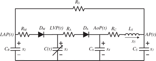
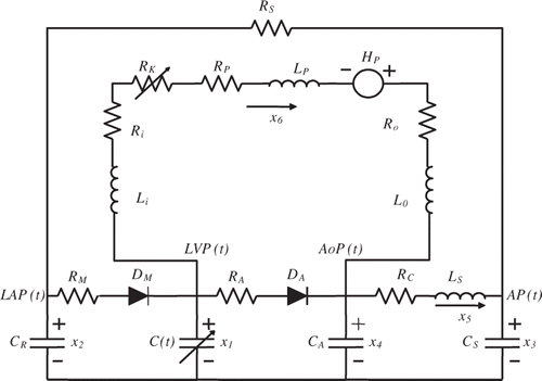
The cardiovascular system can be represented by a 5th order circuit model and the LVAD pump can be simulated by a 1st order circuit model. Combining both models will result in a 6th order model that has a minimum number of parameters that can offer enough complexity to give an accurate representation of the heart and the LVAD.
shows the 5th order model of the cardiovascular system. This model is adopted from previous work Citation13 where every resistance, inductance, capacitance and diode used in the model is well explained and a standard value is provided in for a typical adult.
Table 1. Cardiovascular model parameters.
There is a need, however, to discuss in more detail some important elements in this circuit like: which represents the systemic vascular resistance. This particular parameter can be used to simulate the level of activity experienced by the patient, where the higher value means that the patient is resting and the lower value means that the arteries are offering less resistance to the blood flow because of the high level of activity of the patient (like running, exercising, etc.)
The left ventricular compliance is the inverse of the elastance function of the heart
. The elastance represents the contractual state of the left ventricle. It relates to the ventricle's pressure and volume according to the following expression:
(2)
where LVP(t) is the left ventricular pressure, LVV(t) the left ventricular volume and V0 a reference volume, which corresponds to the theoretical volume in the ventricle at zero pressure. The elastance function E(t) can be approximated mathematically. In our work, we use the expression:
(3)
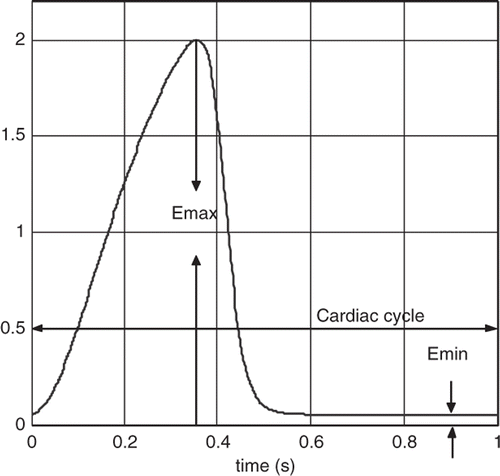
where E(t) represents the elastance of the heart, as shown in . En(tn) the normalized elastance (also called ‘double hill’ function) Citation14 represented by the expression:
(4)
In the expression above, En(tn) is the normalized elastance, tn = t/Tmax, Tmax = 0.2 + 0.15tc and tc the cardiac cycle interval, i.e. tc = 60/HR, where HR is the heart rate. Notice that E(t) is a rescaled version of En(tn) and the constants Emax and Emin are related to the end-systolic pressure volume relationship and the end-diastolic pressure volume relationship, respectively. shows a plot of EH(t) for a healthy heart with Emax = 2 and Emin = 0.06 mm Hg mL−1, and a heart rate of 60 beats per minute. For a heart with cardiovascular disease, the elastance expression used in our model is scaled using the value of Emax which can be varied from 1 to 0.25 mm Hg mL−1 to represent mild to severe HF, respectively.
and
are the ideal diode representations of the aortic and mitral valves. The opening and closing of these valves are controlled by the pressures across them. They are used to simulate the dynamics of the two valves and hence the four phases of the cardiac cycle, mentioned in , are achieved.
Table 2. Phases of the cardiac cycle.
3. The combined LVAD-cardiovascular model
The LVAD pump can be modelled as a 1st order system. When added to the 5th order model in , the result will be a 6th order model that is shown in . The pump functions in parallel to the heart of the patient, hence the parallel connection of the LVAD pump between the left ventricle and the aorta. indicates the six state variables for this circuit model.
Table 3. State variables in the cardiovascular model.
The LVAD considered in this article is a rotary mechanical pump connected with two cannulae between the left ventricle and the aorta. The LVAD pumps blood continuously from the left ventricle into the aorta. The pressure difference between the left ventricle and the aorta is characterized by the following relationship:
(5)
In the expression above, Hp is the pressure (head) gain across the pump and Q the blood flow rate through the pump. The parameters, Ri, Ro and Rp represent the flow resistances and Li, Lo and Lp represent the flow inertances of the cannulae and pump, respectively. Values for these parameters are shown in .
Table 4. Parameter values in LVAD model.
The nonlinear time-varying resistance Rk in (7) has the form:
(6)
Rk is included in the model to characterize the phenomenon of suction. Rk is zero when the pump is operating normally and is activated when LVP(t) (x1) becomes less than a predetermined small threshold 1, a condition that represents suction. The value of Rk when suction occurs increases linearly as a function of the difference between LVP(t) and
. The parameter
is a cannula-dependent scaling factor. The values used for the suction parameters are
and
.
The pressure gain across the pump Hp is modelled using the direct relation between the electric power supplied to the pump motor Pe and the hydrodynamic power generated by the pump Pp scaled by the pump efficiency as
. Furthermore, the electric power may be written in terms of the supplied voltage V and the supplied current i(t) to the pump motor as
, while the hydrodynamic power may be written in terms of the pump head or pressure gain Hp and the pump flow Q as
where
is the density of the reference fluid and g the acceleration of gravity (
). Combining these expressions yields:
(7)
Or
(8)
where
. For a typical LVAD, after applying the appropriate conversion factors and assuming a pump motor supplied voltage
as well as a pump efficiency of 100% (assuming that most losses are accounted for by the pressure losses induced by Rp and Lp), the constant
can be computed to be
.
Substituting (8) in (5), we obtain the nonlinear state equation governing the behaviour of the LVAD as:
(9)
where
and
. Note that it is important to validate the numerical solution when expression (9) is used by ensuring that the system does not allow for operation at zero pump flow Q(t) at any point during the cardiac cycle since Equation (9) exhibits its nonlinearity with the pump flow Q(t) in the denominator.
When combined with the model of the left ventricle, the LVAD state equation model in (9) will yield a model that is controlled by the pump motor current i(t) as desired. Furthermore, using the relation between the pump pressure Hp and the pump speed Citation10:
(10)
An expression for the pump speed in terms of the pump motor current can then be derived as follows:
(11)
Here . Note that it is now clear how the heart hemodynamic through Q(t) influence directly, in a highly nonlinear manner, the pump speed
.
The state space representation of the combined model can then be written in the following form:
(12)
where
(13)
and
(14)
where the
expression is defined by:
(15)
4. Development of a feedback control
The aim of the feedback controller is to adjust the LVAD speed to provide the required amount of blood flow depending on the level of activity of the patient. The current technology does not allow the implantation of sensors inside the human heart for long-term applications; hence there is a need to depend on the pump flow, which is accessible through the installation of a flow-meter sensor inside the pump cannulae, as a feedback variable to automatically adjust and control the pump motor current which in turn controls the pump speed.
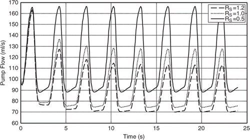
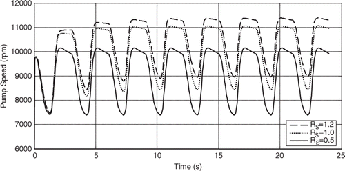
The results shown in are obtained by simulation (using the 6th order model presented above) and reveal that the mean pump flow decreases as the systemic vascular resistance (RS) increases while maintaining the pump motor current constant, see Citation11. Furthermore, this shows that the pump flow signal can be used as an input variable to estimate the patient's systemic resistance as well as to adjust the pump motor current to achieve a mean pump flow that satisfies the patient's physiological demand. shows how the mean pump speed is increased spontaneously as the RS increases and that is due to (11) where you can see the pump flow being the reciprocal for
.
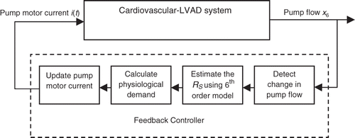
A block diagram for the proposed feedback controller is shown in . The controller consists of four stages of data acquisition, decision making, estimation and adjustment of the pump motor current. During the first stage, labelled ‘detect change in pump flow’, the mean pump flow signal is continuously read until a change is detected. This change is evidence that the activity level of the patient has changed and there is a need to adjust the pump motor current to respond to the new physiological demand. The first stage can be thought of as a gate to the rest of the feedback controller blocks. The controller will only work if the first block sends a signal as a response to a change in the mean pump flow.
During the second stage, labelled ‘Estimate the RS using the 6th order model’, the new RS is estimated by adjusting the numerical value of Rs in the 6th order model until the resulting mean pump flow (x6) matches the mean pump flow read in the previous stage. This is accomplished by setting the problem up as an optimization problem aimed at minimizing an objective function formulated as the absolute value of the difference between these mean pump flows. Details of this approach are provided in the next section.
During the third stage, labelled ‘Calculate physiological demand for estimated RS’, the physiological demand or required mean pump flow under the current activity level is determined by imposing the value of RS found during the previous stage into the 5th order model with to represent a healthy heart. This is done since the overall objective of the controller is to determine the actual output of a healthy heart under the current level of activity, characterized by the estimated RS, and try to match it with the LVAD.
During the fourth stage, labelled ‘Update Pump Motor Current’, the pump motor current i(t) will be adjusted until the mean pump flow reaches the physiological demand for the current level of activity calculated in the previous stage. Again, this requires an optimization approach aimed at reducing an objective function formulated as the absolute value of the difference between the physiological demand and the adjusted mean pump flow. This process is detailed in the next section.
5. Methodology and results
As discussed in the previous section, the change in the mean pump flow while the control parameters are fixed is an indication of a change in the level of activity of the patient (change in RS). This requires the estimation of the new RS for the patient which can be accomplished using a one-dimensional search algorithm. The Fibonacci search algorithm was chosen for this purpose because of its inherent advantage of having a predefined number of iteration before a solution is obtained. The number of iterations is based on the level of accuracy (error tolerance) chosen for the application. The following objective function is to be minimized:
(16)
Here, is the mean pump flow produced by the estimated
(RS) and
the target mean pump flow caused by the change of activity.
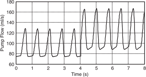
shows a simulation of a patient initially at rest who then becomes more physically active. This simulation is modelled by a change in RS from 1 to 0.5 mmHg s mL−1.
The Fibonacci search was then used to minimize the objective function in (16) to estimate this change in RS. The number of iterations required to arrive at a converged solution was predetermined based on both the possible range of RS's and the tolerance required; the former is assumed to be between 0.4 and 1.4 mmHg s mL−1 (this is the range of possible values of RS) while the latter was established as 0.01 mmHg s mL−1 (accepted tolerance for such application). Hence:
(17)
Here, the number of required iterations, n, is determined as the nth Fibonacci number larger than the search range divided by the tolerance. In this case, the 11th Fibonacci number satisfies this criterion.
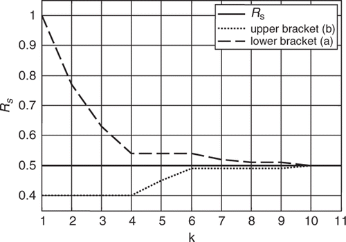
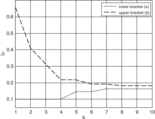
The Fibonacci search algorithm is then executed evaluating the objective function in (16) by running the 6th order model with each of the iterative estimates of RS. The search bracket is narrowed down at every iteration step until the convergence criterion is met after the nth iteration. This process is shown in .
Although the search interval was originally set for values of RS between 0.4 and 1.4 mmHg s mL−1, prior knowledge of the system could allow to have started from a narrower interval. That is, it could have been assumed a priori that the increase in mean pump flow signal was evidence of a decrease in RS and therefore start with a bracket between 0.4 and 1.0 mmHg s mL−1 instead, for example, leading to a smaller number of required iterations.
Once the RS is estimated, a similar approach is then used to adjust the pump motor current to provide the physiological demand. The objective function to be minimized in this case is:
(18)
where CO (cardiac output) is the patient's physiological demand estimated by running the 5th order model for a healthy heart (Emax = 2) with the estimated value of RS from the previous minimization process (RS = 0.5 mmHg.s mL−1 in this case), and
the mean pump flow provided by the iterative estimate of the pump motor current
.
For the case being implemented herein, the physiological demand (CO) was found to be 148.9 mLs−1, larger than the current pump flow of 115.3 mLs−1 achieved by a pump motor current of 0.1 amp, therefore, an increase of the pump motor current is necessary to achieve the goal of meeting the physiological demand. The initial bracket for the pump motor current was then established between 0.1 and 0.65 amp while a tolerance of 0.01 amp was set, leading to a predetermined number of 10 iterations to reach convergence. shows the evolution of the bracket throughout the Fibonacci search algorithm.
6. Conclusions
A new feedback control system is formulated in this article to automatically adjust the pump motor current of a LVAD to provide the blood flow required by the current level of activity of the patient. This is accomplished by first estimating the systemic vascular resistance (RS) of the patient from a coupled LVAD-cardiovascular model using information from measured LVAD pump flow. Furthermore, the estimated RS is used in a patient-specific cardiovascular model that assumes a healthy heart, to determine the demand in terms of blood flow. Once the physiological demand is established, the current supplied to the pump motor of the LVAD can be adjusted to achieve the desired blood flow through the cardiovascular system. This process can be performed automatically in a real-time basis using information that is readily available and thus rendering a high degree of applicability. Results from simulated data show that the feedback control system is fast and very stable.
Acknowledgement
This study was supported in part by the US National Science Foundation under grant ECCS-0701365.
References
- Lloyd-Jones, D, Adams, RJ, Brown, TM, Carnethon, M, Dai, S, De Simone, G, Ferguson, TB, Ford, E, Furie, K, Gillespie, C, Go, A, Greenlund, K, Haase, N, Hailpern, S, Ho, PM, Howard, V, Kissela, B, Kittner, S, Lackland, D, Lisabeth, L, Marelli, A, McDermott, MM, Meigs, J, Mozaffarian, D, Mussolino, M, Nichol, G, Roger, VL, Rosamond, W, Sacco, R, Sorlie, P, Stafford, R, Thom, T, Wasserthiel-Smoller, S, Wong, ND, and Wylie-Rosett, J, 2010. Heart disease and stroke statistics – 2010 update: A report from the American Heart Association, Circulation 121 (2010), pp. e46–e215.
- Volkron, M, Schima, H, Huber, L, Benkowski, B, Morello, G, and Wieselthaler, G, , Control of implantable axial blood pumps based on physiological demand, Proceedings of the 2006 American Control Conference, Minneapolis, MN, 14–16 June, 2006.
- Park, SJ, Tector, A, Piccioni, W, Raines, E, Gelijns, A, Moskowitz, A, Rose, E, Holman, W, Furukawa, S, Frazier, OH, and Dembitsky, W, 2005. Left ventricular assist devices as destination therapy: A new look at survival, J. Thorac. Cardiovasc. Surg. 129 (1) (2005), pp. 9–17.
- Carr, CM, Jacob, J, Park, SJ, Karon, BL, Williamson, EE, and Araoz, PA, 2010. CT of left ventricular assist devices, RadioGraphics 30 (2010), pp. 429–444.
- Olsen, DB, 2000. The history of continous-flow blood pumps, Artif. Organs 24 (6) (2000), pp. 401–404.
- Bertram, CD, 2005. Measurement for implantable rotary blood pumps, Physiol. Meas. 26 (2005), pp. R99–R117.
- Saito, I, Ishii, K, Isoyama, T, Ono, T, Nakagawa, H, Shi, W, Inoue, Y, and Abe, Y, , Preliminary study of physiological control for the undulation pump ventricular assist device, Proceedings of the International Conference of IEEE Engineering in Medicine and Biology Society, Buenos Aires, Argentina, 31 August – 4 September 2010, pp. 5218–5221.
- Giridharan, G, Pantalos, G, Koenig, S, Gillars, K, and Skliar, M, 2005. Achieving physiological perfusion with ventricular assist devices: Comparison of control strategies. Portland, OR: Proceedings of the 2005 American Control Conference; 2005, pp. 3823–3828.
- Wu, Y, Allaire, P, Tao, G, and Olsen, D, , Modeling, estimation and control of cardiovascular systems with a left ventricular assist device, Proceeding of American Control Conference, Portland, OR, 8–10 June 2005, pp. 3841–3846.
- Simaan, MA, Ferreira, A, Chen, S, Antaki, JF, and Galati, DG, 2009. A dynamical state space representation and performance analysis of a feedback-controlled rotary left ventricular device, IEEE Trans. Control Syst. Technol. 17 (1) (2009), pp. 15–28.
- Akimoto, T, Yamazaki, K, Litwak, KN, Tagusari, O, Mori, T, Antaki, JF, Kameneva, MV, Watach, MJ, Umezu, M, Tomioka, J, Kormos, RL, Koyanagi, H, and Griffith, BP, 1999. Rotary blood pump flow spontaneously increases during exercise under constant pump speed: results of a chronic study, Artif. Organs 23 (8) (1999), pp. 797–801.
- Dunlap, RA, 1997. The Golden Ratio and The Fibonacci Numbers, . Singapore: World Scientific Publishing Co. Pte. Ltd.; 1997.
- Faragallah, G, Wang, Y, Divo, E, and Simaan, MA, , A new current-based control model of the combined cardiovascular and rotary left ventricular assist device, Proceeding of 2011 American Control Conference, San Francisco, CA, 29 June–1 July 2011.
- Simaan, M, Faragallah, G, Wang, Y, and Divo, E, 2011. Reyes, G, ed. New Aspects of Ventricular Assist Devices. Croatia: InTech, Rijeka; 2011.
