Abstract
We use the linear sampling method (LSM) to identify a crack with impedance boundary conditions from far-field measurements at a fixed frequency. This article extends the work of Cakoni–Colton [F. Cakoni and D. Colton, The linear sampling method for cracks, Inverse Probl. 19 (2003), pp. 279–295] where LSM has been used to reconstruct a crack with impedance boundary conditions on one side of the crack and a Dirichlet boundary condition on the other one. In addition, we present two methods to also reconstruct the impedance parameters whence the geometry is known. The first one is based on the interpretation of the indicator function produced by the LSM, while the second one is a natural approach based on the integral representation of the far-field in terms of densities on the crack geometry. The performance of the different reconstruction methods is illustrated through numerical examples in a 2D setting of the scattering problem.
1. Introduction
We are concerned in this work with the inverse scattering problem from a crack with impedance boundary conditions. More precisely we shall investigate the application of the linear sampling method (LSM) to retrieve the geometry of the crack from multi-static far-field data at a given frequency. This inverse problem has its application in non-destructive testing of dielectrics (e.g. to monitor the quality of wood, composite materials, thin coatings, etc.) where one is interested in identifying infinitely thin inclusions or crack-type faults using electromagnetic or acoustic waves.
As compared to previous works on this type of problem and on employed methods Citation1–5, the originality of the present one relies on considering the case of impedance boundary conditions on both sides of the crack. This induces more technical difficulties in the justification of the method and raises new questions for the numerical algorithm. For instance, the numerical procedure proposed in Citation1 works only if a Dirichlet boundary condition is verified on one side of the crack. In that case the use of monopoles as test functions for the far-field equation is sufficient to obtain good reconstructions of the geometry. This is no longer the case if the impedance boundary conditions hold on both sides of the crack and the impedance values are small. In those cases the use of dipoles is important. The main difficulty then relies on the choice of the orientation of the dipole (or equivalent probing ‘small’ crack). On the basis of the theoretical justification of the LSM we propose a minimization procedure that enforces the correct choice of this orientation.
Prior to considering the inverse problem, we propose a study of the forward problem using an integral equation approach. This part is then used in deriving the theory associated with LSM and also in designing a numerical method to solve the direct problem and generate the synthetic data needed for the inverse scheme. The theoretical developments of this first part are inspired by Citation1. We also quote the work of Citation6 for the study of the direct problem using an integral equation approach in Hölder spaces and the work of Citation7 for the study of the inverse problem using a different sampling method.
After having reconstructed the geometry of the crack, it would be useful to obtain more information about the crack for example by determining the impedance values. To do so, we shall apply two approaches. The first one is a natural approach based on the expression of the far-field pattern and on the scattering problem. First, the measurement of the far-field pattern is used to find the values of the jump of the scattered wave and its normal derivative on the crack. These values are then used to retrieve the Cauchy data associated with the total field on each part of the crack and an estimate of the impedance values. This kind of approach is similar to the one used in Citation2 for planar cracks where Fourier expansion is used to evaluate the total field on the crack. The second approach is based on an interpretation of the solution of the far-field equation in terms of associated scattered field and on the reconstructed crack. This approach is similar to the one used in Citation8 for an obstacle with an impedance boundary condition.
For an overview of recent works on the impedance parameters identification we refer to Citation7,Citation9 and the references therein). We also quote that the extension of the first part of the current work to the factorization method Citation10 will be the subject of a forthcoming paper.
This article is organized as follows. In Section 2, the direct problem is introduced along with a study of the uniqueness and existence of the solution using an integral equation method. In Section 3, we introduce the inverse problem and we describe our formulation of the LSM along with the mathematical justifications. Then, we propose and test different sampling schemes for different shapes of the cracks and different values of the impedances. Lastly, we develop in Section 4 two different approaches to determine the unknown impedance values.
2. The direct scattering problem for a crack with impedance boundary conditions
Let σ ⊂ ℝm, m = 2 or 3, be a smooth non-intersecting m − 1 manifold. For further considerations, we assume that σ can be extended to an arbitrary smooth boundary ∂Ω enclosing a bounded domain Ω in ℝm. The normal vector ν on σ coincides with the outward normal vector to ∂Ω.
Impedance type boundary conditions on σ lead to the following problem
(1)
(2)
where the wave number κ is positive and λ± ∈ L∞(σ) are the given (complex-valued) impedance functions with non-negative imaginary part. Notice that
and
for x ∈ σ. The total field u = ui + us is decomposed into the given incident plane wave ui(x, d) = eiκd·x with unitary direction d and the unknown scattered field us which is required to satisfy the Sommerfeld radiation condition
(3)
uniformly in all directions
.
The ‘free space fundamental solution’ to the Helmholtz equation is given by
(4)
with x ≠ y and
being the Hankel function of the first kind of order zero.
In order to formulate the scattering problem more precisely we need to define the trace spaces on σ. If , H1/2(∂Ω) and H−1/2(∂Ω) denote the usual Sobolev spaces we define the following spaces Citation11:
Now we denote by H−1/2(σ) and
the dual spaces of
and H1/2(σ) respectively. Let us also introduce the boundary integral operators
defined for regular densities ψ and ϕ by
and the corresponding operators
defined on σ. These restricted operators have the following mapping properties Citation11
Using the notation
(5)
the problem (1)–(3) is a special case of the following problem:
Impedance crack problem (ICP): Given g± ∈ H−1/2(σ) such that and (λ±) ∈ L∞(σ) with Im(λ±) ≥ 0 and (λ + + λ−)−1 ∈ L∞(σ), find
satisfying the Sommerfeld radiation condition (3) and
(6)
(7)
The aim of this section is to prove the existence of the solution of the (ICP), since the following uniqueness result can be found in Citation2,Citation6:
Theorem 2.1
The (ICP) has at most one solution.
To prove the existence of the solution of the (ICP), we use a boundary integral equations approach (see Citation2 for a sound soft crack and a sound hard crack, Citation1 for a partially coated crack and Citation6 for a 2D impedance crack when λ + = λ− is Hölder continuous).
We define and
, the jump of us and ∂νus respectively, across the crack σ.
Lemma 2.2
Assume that (λ + + λ−)−1 ∈ L∞(σ) and g± ∈ H−1/2(σ) such that . The scattered field us is solution of the (ICP) if and only if
(8)
where the matrix operator
is given by
(9)
Proof
If us is a solution of the (ICP) then and
(see Lemma 2.2 in Citation1). Using the Green representation formula, the following relation holds for
(see theorem 2.24 in Citation2):
(10)
where Φ is the fundamental solution to the Helmholtz equation given by (4).
Next by making use of the jump relations of the single and double layer potentials across ∂Ω Citation11, we obtain from (10)
(11)
(12)
Moreover, from the boundary condition (7) and using (5), we have
(13)
(14)
Finally, by combining the relations (11)–(14), we show that ([us], [∂νus])T solves the system of Equations (8). Conversely, assume that ([us], [∂νus])T satisfies (8)–(9), so
(15)
and
(16)
The potential us, defined by (10), belongs to
and satisfies the Helmholtz equation in
and the Sommerfeld radiation condition. It remains to show that us satisfies the boundary condition (7). To this end, we first inject (12) into (15) and (11) into (16). We obtain
(17)
(18)
Multiplying (18) by λ± and adding the results to (17), we obtain that
Therefore, the field us given by (10) is a solution of the (ICP).▪
Lemma 2.3
The operator Aσ given by (9) has a trivial kernel.
Proof
Let satisfying
.
Define the potential
This potential belongs to
and satisfies the Helmholtz equation in
and the Sommerfeld radiation condition. Moreover, using the jump relations of the single and double layer potentials across σ, we get
Hence,
(19)
Therefore, as in the proof of Lemma 2.2, we show that
satisfies
and the Sommerfeld radiation condition. Then, from the uniqueness of the solution of this system, we have v = 0 and we conclude, by (19), that α = β = 0.▪
Lemma 2.4
Assume that (λ + + λ−)−1 ∈ L∞(σ). The operator given by (9) has a bounded inverse.
Proof
Let and
be the extension by zero to ∂Ω of
and
, respectively.
Let A∂Ω be the operator defined on H1/2(∂Ω) × H−1/2(∂Ω) → H1/2(∂Ω) × H−1/2(∂Ω) by
(20)
where
such that
and
. A can be decomposed as A = Ac,Ω + A0,Ω, where
(21)
and
(22)
We denote by T0,∂Ω the boundary integral operator corresponding to the Laplace operator, defined as T∂Ω by replacing the kernel Φ(x, y) by
(23)
The operator −T0,∂Ω is coercive on ∂Ω. Consequently, we can directly deduce that A0,∂Ω is invertible.
We now prove that the operator Ac,∂Ω is compact. In fact, Tc,∂Ω ≔ T∂Ω − T0,∂Ω is a compact operator since it has a continuous kernel.
Since the injection from to
is compact and
, the operators
and
are also compact from
to
.
On the other hand, is a compact operator from
to
. The operator S∂Ω is continuous from
to
. Thus
is compact from
to
. The operator K∂Ω is continuous from
to
, which implies that
is compact from
to
. We conclude that Ac,∂Ω: H1/2(∂Ω) × H−1/2(∂Ω) → H−1/2(∂Ω) × H−1/2(∂Ω) is a compact operator.
Let us prove now the same properties for Aσ. A decomposition of Aσ can be given as A0,σ + Ac,σ where A0,σ and Ac,σ are, respectively, defined by
and
(24)
We can observe that Ac,σ is the restriction of Ac,∂Ω to
on σ. Then, we can directly deduce the compactness of this operator. The coercivity of A0,σ is deduced from the coercivity of −T0,σ. In fact, we have for all
for some α > 0. Therefore
which leads to the coercivity of the operator −T0,σ on σ. Consequently, the operator A0,σ is invertible. In fact, let
and
such that
This is equivalent to
Consequently
Therefore the invertibility of Aσ,0 is equivalent to the invertibility of T0,σ.
Finally, Aσ is a Fredholm operator with index zero and since Aσ is injective (see Lemma 2.3) we conclude that it has a bounded inverse.▪
As a consequence of these lemmas, we have the following result
Theorem 2.5
The (ICP) has a unique solution given by
(25)
where ([us], [∂νus]) is the unique solution of the system of integral equations (8).
A detailed discussion about the numerical implementation of the (ICP) using a Galerkin method can be found in Citation12.
We recall that the solution of the (ICP) has the asymptotic behaviour of an outgoing spherical wave Citation13
(26)
where u∞ is the far-field pattern of the scattered wave,
,
and r = |x|.
3. The inverse problem
3.1. Settings and theoretical results motivating the LSM
In this section, we adapt the LSM for scattering by a partially coated crack Citation1 to the following inverse problem. We shall keep the same hypothesis on λ± as in Section 2.
Inverse scattering by an impedance crack (IIC): Given the far-field pattern u∞(·, ·) on 𝕊m−1 × 𝕊m−1 of the solution to (ICP), reconstruct the crack σ.
To solve the (IIC) by the LSM method, we first define the far-field operator
(27)
and consider the far-field equation
(28)
where
is given by
(29)
(30)
Notice that
is the far-field pattern of the potential ΦL defined by
(31)
with densities
and
, for any smooth non-intersecting open arc L ∈ ℝm−1.
We will characterize the crack σ by the behaviour of an approximate solution gL of the far-field equation (28).
To prove the existence of an approximate solution of (28), we factorize the operator F as F = Bℋ where maps the boundary data (g + , g + − g−) to the far-field pattern of the solution of (ICP) and ℋ is the trace operator defined by
where vg is the Herglotz wave function of kernel g ∈ L2(𝕊m−1),
(32)
We will show that the traces of the solution of the (ICP) on both sides of σ can be approximated by the appropriate traces of the Herglotz wave function vg.
Lemma 3.1
The operator ℋ is injective and has a dense range.
Proof
Let g ∈ L2(𝕊m−1) be an element of the kernel of ℋ. Then,
Since by assumption (λ + + λ−) ≠ 0 then vg = 0 and ∂νvg = 0 on σ0 ⊂ σ. From the unique continuation principle it implies that vg = 0 in ℝm and therefore g = 0 which proves that ℋ is one to one.
The main idea of the proof of the second part of the lemma is to show that ℋ*, the adjoint operator of ℋ, is injective.
To this end, we first determine the expression of ℋ*. Let g ∈ L2(𝕊m−1) and , then
satisfies
where
.
By changing the order of integration and using (32),
Therefore, for d ∈ 𝕊m−1, the operator ℋ* is given by
We observe that ℋ* is the far-field pattern of the potential
for
. This function is well defined in
since α and β can be extended by zero to functions in H1/2(σ). Moreover,
satisfies the Helmholtz equation and the Sommerfeld radiation condition.
Therefore, if ℋ*(α, β) = 0, the far-field pattern of V is zero and from Rellich's lemma and the unique continuation principle we conclude that V = 0 in . Then, by the jump relations of the layer potentials, we have [V] = −γα and
. This implies that
Thus, since by assumption (λ + + λ−)−1 ∈ L∞(σ), α = β = 0. We conclude that the operator ℋ* is injective and using Lemma 2.10 in Citation11 the operator ℋ has a dense range.▪
In the next step, we provide some properties of the operator B. We need to introduce the operators given by
(33)
and
defined by
(34)
Lemma 3.2
The operator M has a bounded inverse and B = γℱM−1.
Proof
For a given , the function
is the far-field pattern of the potential
The function
satisfies the Helmholtz equation in
and the Sommerfeld radiation condition. In addition, following the proof of Lemma 2.3, we show that ϕ = [P], ψ = −[∂νP] and
where
is given by (34). This operator is related to the matrix Aσ defined by (9). More precisely,
with
defined by
(35)
Since (λ + + λ−)−1 ∈ L∞(σ), 𝒞 is an invertible operator and by Lemma 2.4,
exists and is bounded.▪
Lemma 3.3
The operator is injective and has a dense range in L2(𝕊m−1).
Proof
The injectivity of ℱ can be proved in the same way as in Lemma 3.1, by replacing the potential V by P.
Proceeding again as in the proof of Lemma 3.1, let g ∈ L2(𝕊m−1) and ,
Therefore, ℱ*(g) = γ(∂νvg, vg)|σ.
Now, if ℱ*(g) = 0 then vg = ∂νvg = 0 on σ.
Thus, as in Lemma 3.1, g = 0 which proves the density of the range of ℱ.▪
Summarizing the previous results, the operator F defined by (27) is factorized as F = ℱM−1ℋ. Hence, the range of F is included in the range of ℱ. Therefore, thanks to the following lemma, there exists an approximated solution of Equation (28).
Lemma 3.4
For any smooth non-intersecting arc L and functions ,
such that (αL, βL) ≠ (0, 0), the function
given by (29) belongs to R(ℱ), the range of ℱ, if and only if L ⊂ σ.
Proof
First assume that L ⊂ σ. Since , it follows from (33) that
.
Now let L ⊄ σ and assume, on the contrary, that . Hence, there exists
and
such that
Thus is the far-field pattern of the potential
Since by definition
is also the far-field pattern of the potential ΦL given by (31) then using Rellich's lemma and the unique continuation principle, the potentials ΦL and P coincide in
.
Let and Bε a small neighbourhood of x0 with Bε ∩ σ = ∅. Then, P is analytic in Bε while ΦL or its normal derivative is not continuous across L which is a contradiction. This proves that
.▪
Theorem 3.5
We assume that L is a non-intersecting smooth open arc. The following is true:
| 1. | If L ⊂ σ; there exists a sequence (gn)n∈ℕ on L2(𝕊m−1) such that
| ||||
| 2. | Otherwise, for any sequence (gn)n∈ℕ ⊂ L2(𝕊m−1) that satisfies
| ||||
Proof
| • | If L ⊂ σ, it is easy to find a bounded solution of the far-field equation (28). In fact, we have | ||||
| • | Let L ⊄ σ and let us assume that | ||||
The integral operator ℱ is compact since it has a regular kernel and M−1 is a bounded operator, so that the operator ℱM−1 is also compact. Consequently,
and by the uniqueness of the limit, we have
We deduce that
and L ⊂ σ which is a contradiction.▪
For the purpose of the numerical experiments, we cannot give a crack characterization by using the norm of vg as suggested in Theorem 3.5 since this norm depends on the impedance values and on the crack σ. However, similar to the case of obstacles with non-empty interior Citation14, we expect that has the same behaviour as
in the sense that
has smaller values when L ⊂ σ, where gL denotes a nearby solution of the far-field equation. The latter heuristic argument can be for instance justified by the fact that, at the discrete level, the Herglotz operator ℋ is invertible. Our indicator function will be then based on
.
3.2. Numerical schemes and results
3.1.1. Numerical scheme
The numerical experiments are conducted in a 2D setting of the problem. We consider n equally distant observation points of the far-field on the unit circle 𝕊1.
(37)
where wj is the arc length between two adjacent points. Let L be a small segment of centre z and with normal ν. Then
(38)
The discrete equation to solve is then
(39)
using a classical Tikhonov regularization and the Morozov principle to fix the regularization parameter. The sampling procedure will consist then in varying z and ν in (38). According to Theorem 3 we expect ‖g‖ (where g is a solution to (39)) to be large except when z ∈ σ and ν is the normal to σ at z.
We shall consider two types of solutions: the first one denoted by gz corresponds to α(z) = 1 and β(z) = 0, the second one denoted by gz,ν corresponds to α(z) = 0 and β(z) = 1.
Remark 1
One can guess from the theoretical section (end of the proof of Lemma 3.4) that for a crack with Neumann boundary conditions (corresponds with vanishing impedances), Lemma 3.4 (and therefore Theorem 3.5) is not verified if αL = 0. The same is true if the impedances are infinite (Dirichlet boundary conditions) and βL = 0. From the numerical point of view, this suggests that gz,ν plays a more important role for small values of the impedances than for larger ones. The numerical reconstructions below will confirm this observation.
First criterion: Since a priori knowledge on the correct orientation of the normal ν is not known a priori, a natural approach would be to consider the use of two independent normals for instance ν1 = (0, 1)T and ν2 = (1, 0)T. At each sampling point z we then compute
(40)
This criterion would provide good reconstructions in the case of obstacles with non-empty interior. However, as we shall observe later, for the case of cracks it may not be efficient if ν1 or ν2 does not coincide with the exact normal to σ at z (see the numerical tests in Section 3.1.2).
Second criterion: Let us define the normal ν as
Therefore, by linearity of Equation (39)
Based on the theoretical justification, the normal ν to σ at z ∈ σ corresponds with the value ζ that minimizes
(41)
The proposed criterion will be the determination on each point z of
(42)
where gz,ν corresponds with ζ that minimizes (41).
3.1.2. Numerical tests
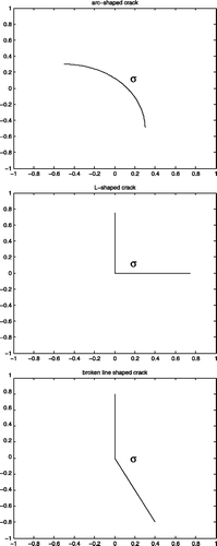
The efficiency of our approach is tested using both criteria for several ranges of the impedance values and for different shapes, namely arc-shaped cracks, L-shaped cracks and angular cracks (). We present in the following figures the isovalues of the right-hand side of (40) and (42). The location of the crack would correspond with the red isovalues in the figures.
In all the numerical tests, we use 100 observation points of the far-field pattern and the same number of incident plane waves. The wavelength is equal to 1 and the synthetic data is corrupted with 1% random noise. The minimization of (41) is simply done by taking the min value of (41) evaluated on 50 equidistant values of ζ. The reconstructions computational time is of order of seconds on a MacBook Pro laptop.
Both criteria give a good reconstruction of the crack for the case of large impedances (Figures ).
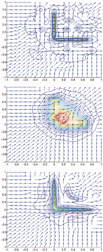
Figure 2. Reconstruction of an L-shaped crack (, middle) with vertices (0.75, 0), (0, 0), (0, 0.75) for λ± = 0.01(1 + i) (top), λ± = 5(1 + i) (middle), λ± = 1000(1 + i) (bottom).
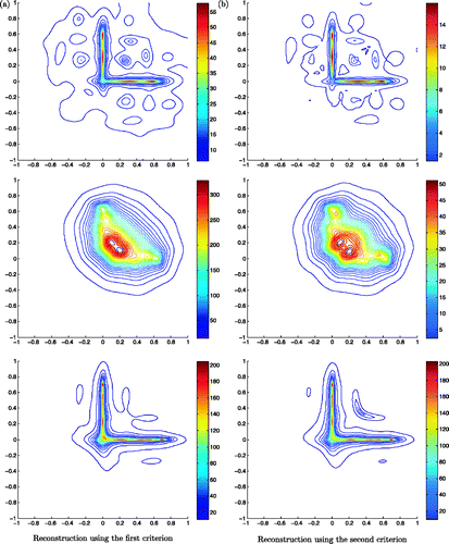
In the case of small impedances, using the first criterion, the result is not satisfactory for all geometries. This is due to the fact that for large impedances we are close to the Dirichlet case, hence the dominant term in (40) is whereas for small impedances we are close to the Neumann case where the dominant term is the one that contains the normal derivatives. shows that if ν1 or ν2 coincides with the exact normal to the crack we have a good reconstruction otherwise only the part of the crack for which the normal coincides with ν1 or ν2 is correctly reconstructed ( and ). Hence having a good approximation of ν is very important for the precision of the result. This problem is fixed by the use of the second criterion as demonstrated by the reconstruction shown in , and .
Figure 3. Reconstruction of an arc-shaped crack (, top) with centre (−0.5, −0.5), radius 0.8 and angle varying from 0 to π/2 for λ± = 0.01(1 + i) (top), λ± = 5(1 + i) (middle), λ± = 1000(1 + i) (bottom).
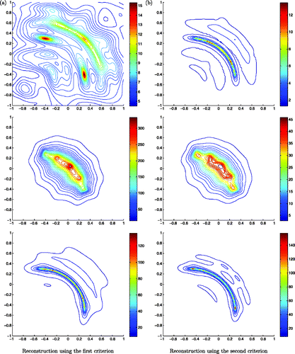
Figure 4. Reconstruction of two segments with endpoints (0, 0.8), (0, 0) and (0, 0), (0.4, −0.8) (, bottom) for λ± = 0.01(1 + i) (top), λ± = 5(1 + i) (middle), λ± = 1000(1 + i) (bottom).
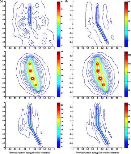
We also observe that the quality of the results deteriorates when the impedance values are intermediate between high and small magnitudes.
To illustrate the correlation between the reconstruction of the normals (i.e. the ν that minimizes (41)) and the precision of the crack reconstruction, we represent these vectors in . We observe that the best crack reconstructions for intermediate values of the impedances correspond with the cases where the normals at the crack are close to the exact ones. For large values of the impedances, the reconstruction of the normal is not correct but has negligible influence on the crack reconstruction (see Remark 1).
4. Determination of the impedance values
After determining the geometry of the crack, a second step would be to get estimates on the impedances values on both sides of the crack. To do so, we develop and compare two different approaches: a so-called natural approach and an approach based on the LSM formalism.
4.1. A natural approach
This approach is based on the expression of the far-field pattern. We recall that
By knowing the crack σ, we can deduce ([u], [∂νu]) on σ by inverting the operator
defined by
This is an ill-posed problem since ℱ is a compact operator. Consequently a regularization is needed. We shall use a Tikhonov regularization by solving
where ζ is a regularization parameter chosen by using the Morozov criterion. From the integral representation of the scattered solution one deduces
Finally, by considering the boundary conditions on σ,
In the case of constant impedance values we prefer using the formula
(43)
which would be less sensitive to pointwise small values of u±. This approach is tested for different shapes, namely a segment, an arc and a broken line (). The results are presented in –.
Table 1. Reconstruction of the average of λ± given by (43) on σ = [−0.5, 0.5] × {0} for n equidistant directions of plane waves starting from θ = 0 with the wavelength λ = 1.
In and , we fix the geometry and provide different estimates of the average of n reconstructed impedance values where n is the number of the different directions of ui for segment and arc-shaped cracks, respectively. Both tables show in general good estimates of the impedance values. One also observes that for the case of arc-shaped cracks, when the imaginary part is relatively high, the accuracy of reconstructed values deteriorates. Since this is not the case of segment, we think that the loss of accuracy is due to the non-convexity of the geometry.
Table 2. Reconstruction of the average of λ± given by (43) on the arc σ centred at (0, 0) with aperture  for n equidistant directions of plane waves starting from θ = 0 till θ = 2π with the wavelength λ=1.
We next test whether the reconstructed impedance is sensitive to errors on the cracks geometries. To do so, we introduce a small perturbation on the geometry of the crack by shifting its vertical position with ϵ. The results shown in and below indicate that a stable approximation is obtained only for kϵ small enough.
Table 3. Reconstruction of the average of λ± given by (43) on a perturbed geometry  where the exact crack is σ=[−0.5, 0.5]×{0} for 100 equidistant directions of plane waves starting from θ=0 till θ=2π and a wavelength λ=1.
4.2. An approach inspired by the LSM algorithm
According to the proof of the main lemma of the LSM (see Theorem 3.5), if L ⊂ σ then ΦL is an approximation of the scattered wave associated to an incident Herglotz wave with the kernel gL solution of the LSM equation (28). Hence we have the following relations:
(44)
We recall that
where
. Hence to estimate the value of the impedance over the small crack L, the following formula can be used, which can be directly deduced from (44) for constant impedance values over L.
(45)
The main advantage of this procedure as compared to the previous one is that a complete knowledge of σ is not required to obtain an approximation of λ± on L. This is particularly attractive for cases where the reconstructed geometry is good only in some parts of the crack. This has been observed for instance for complex geometries with impedances having ‘intermediate’ values.
Before investigating the cases where L is a part of σ let us consider similar configurations as for the previous approach. Namely we take L = σ = [−0.5, 0.5] × {0}. Since (α, β) should be in , we can choose β as a constant function and α as a function that vanishes on the vertices of σ given by
The results of show that a good reconstruction of the impedance values is obtained when using this criterion. The accuracy of the results seems to be not very sensitive to the values of β for the adopted choice of test functions.
Table 4. Reconstruction of λ± given by (43) on a perturbed geometry  where the exact crack is σ=[−0.5, 0.5] × {0} for 100 equidistant directions of plane waves starting from θ = 0 till θ = 2π and a wavelength λ = 4.
Table 5. Reconstruction of the average of λ± using formula (45) on L = σ = [−0.5, 0.5]×{0}.
As done in the first approach we test also the sensitivity of this approach to small perturbations of the exact geometry ( and ). We qualitatively observe similar behaviour as in the first approach, namely kϵ should be small enough to ensure a good accuracy. However, we can state that the second method seems to be more sensitive to error in the geometry than the first one.
Table 6. Reconstruction of λ± using formula (45) on the perturbed geometry  where the exact crack is σ = [−0.5, 0.5]×{0} for the wavelength λ = 1 and β = 6.
Table 7. Reconstruction of λ± using formula (45) on the perturbed geometry  where the exact crack is σ = [−0.5, 0.5]×{0}, β = 6 and the wavelength λ = 4.
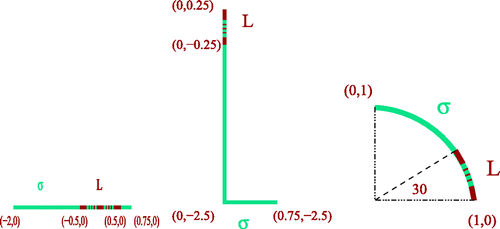
We now consider the cases where L is only a part of σ. We test this issue for three different geometries given in .
In the first experiment, we assume that L = [−0.5, 0.5] × {0} is a part of the exact crack σ = [−2, 0.75] × {0}. shows that a good estimate of the impedance is also obtained in this case.
Table 8. Reconstruction of the average of λ± using formula (45) when L = [−0.5, 0.5] × {0} is a part of the exact crack σ = [−2, 0.75] × {0} (see Figure 6, left).
In the following test, we show that even for a complex shape as the L-shaped crack we can get good reconstructions. In , σ is an L-shaped crack with vertices (0, 0.25), (0, −2.5), (0.75, −2.5) and L = {0} × [−0.25, 0.25] for a constant β and
Table 9. Reconstruction of the average of λ± using (45) on L = {0}×[−0.25, 0.25] which is a part of the exact L-shaped crack σ in Figure 6 for the wavelength λ = 1.
Finally, let L be a part of the arc shown in (right). The results in show that a good approximation of the exact values of the impedance is obtained on the known part of the exact crack.
Table 10. Reconstruction of the average of λ± on L using formula (45) where L is the arc centred at (0, 0) with aperture  which is a part of the exact crack σ (see Figure 6, right) for the wavelength λ=1.
Acknowledgements
This work is supported by the Ministère de l'Enseignement Supérieur, de la Recherche Scientifique et de la Technologie (MESRST, TUNISIA) under the LAB-STI-02 program and the Franco-Tunisian INRIA-DGRSRT 08/I10 scientific program.
References
- Cakoni, F, and Colton, D, 2003. The linear sampling method for cracks, Inverse Probl. 19 (2003), pp. 279–295.
- Delbary, F, , Identifications de fissures par des ondes acoustiques, Ph.D. diss. Université de Paris 6, 2006.
- Kirsch, A, and Ritter, S, 2000. A linear sampling method for inverse scattering from an open arc, Inverse Probl. 16 (2000), pp. 89–105.
- Zeev, N, and Cakoni, F, 2009. The identification of thin dielectric objects from far-field or near field scattering data, SIAM J. Appl. Math. 69 (2009), pp. 1024–1042.
- Zeev, N, 2011. Identification of surface impedance of thin dielectric objects from far-field data, Inverse Probl. 27 (2011), p. 025011.
- Kress, R, and Lee, KM, 2003. Integral equation methods for scattering from an impedance crack, J. Comput. Appl. Math. 161 (2003), pp. 161–177.
- Liu, JJ, and Sini, M, 2010. Reconstruction of cracks of different types from far-field measurements, Math. Meth. Appl. Sci. 33 (2010), pp. 950–973.
- Cakoni, F, and Colton, D, 2003. The determination of the surface impedance of a partially coated obstacle from far-field data, SIAM J. Appl. Math. 2 (2003), pp. 709–723.
- Ivanyshyn, O, and Kress, R, 2011. Inverse scattering for surface impedance from phase-less far-field data, J. Comput. Phys. 9 (2011), pp. 3443–3452.
- Kirsch, A, and Grinberg, N, 2008. The Factorization Method for Inverse Problem, Oxford Lecture Series in Mathematics and its Applications, Vol. 36. Oxford: Oxford University Press; 2008.
- McLean, W, 2000. Strongly Elliptic Systems and Boundary Integral Equations. Cambridge: Cambridge University Press; 2000.
- Hassen, FBen, Boukari, Y, and Haddar, H, , Application of the linear sampling method to retrieve cracks with impedance boundary conditions, Tech. Rep. INRIA 7478, 2010; available at http://hal.archives-ouvertes.fr/inria-00543901/PDF/RR-7478.pdf.
- Colton, D, and Kress, R, 1998. Inverse Acoustic and Electromagnetic Scattering Theory, Applied Mathematical Sciences. Vol. 93. Berlin: Springer-Verlag; 1998.
- Cakoni, F, and Colton, D, 2006. Qualitative Methods in Inverse Scattering Theory. Berlin: Springer-Verlag; 2006.
