Abstract
A shape identification scheme is developed in this article to determine the shape of the inaccessible parts of a two-dimensional object made of functionally graded material using the measured temperatures on its accessible parts. The proposed method is based on minimization of the differences between measured and calculated temperatures. The smoothed fixed grid finite element method which is a new approach based on the non-boundary-fitted meshes and the gradient smoothing technique are used for the solution of direct problem and shape sensitivity analysis. The boundary parameterization technique using splines is also adopted to manipulate the shape variations. The conjugate-gradient method is used as the optimization algorithm and some numerical examples are solved to evaluate the applicability of the proposed method in the context of functionally graded materials.
1. Introduction
The temperature field can directly be obtained in the heat conduction problems when the geometric shape of the problem domain, boundary conditions, initial conditions and material properties are given. The problem can also be inversely solved for one of these parameters if the temperature values at some points are known Citation1. For the heat transfer problems, the inverse geometry problems (IGPs) are a class of the inverse problems in which the geometric shape of inaccessible parts of the domain is unknown and must be determined according to the measured temperatures on the accessible parts of the domain. Some industrial applications of IGPs for heat transfer problems have been reported in Su and Chen Citation2. The main goal of this article is to present a numerical method for solving IGPs including functionally graded materials (FGMs). FGMs are new materials with interesting characteristics and have special applications in the aerospace technology Citation3.
Solution of IGPs is usually an iterative process and is carried out through the solutions of several forward problems. These problems can be considered as the variable domain problems in which the process starts with an initial guess for the unknown geometry and has to be modified in each iteration to fulfil some requirements, e.g. to minimize the differences between the measured and the computed temperatures.
Among several numerical methods proposed to obtain the solution of the forward problem, the most appealing one is the boundary element method (BEM). In the BEM, there is no need to discretize the problem domain into meshes and it makes BEM as the most preferable method for IGPs Citation4,Citation5. However, BEM has some drawbacks which limit its application in some problems. For instance, solution of problems involving FGMs is not so trivial with BEM and may require domain discretization Citation6. The other method is the finite element method (FEM). The main drawback of finite element analysis is that the mesh must be modified whenever the geometry of the problem is changed Citation7. An approach to decrease FEM dependency on conventional mesh is using non-boundary-fitted meshes (NBFMs). Using NBFMs in the analysis of variable domain problems reduces the analysis costs significantly, because there is no need to modify the mesh or re-meshing in iterations where the problem geometry is changed. The fixed grid finite element method (FGFEM) Citation8,Citation9 uses a fixed NBFM to perform a finite element analysis. In this method, the homogenization technique Citation10 (as used in Garcia and Steven Citation8) or a technique based on numerical integration (as used in Daneshmand and Kazemzadeh-Parsi Citation9) is implemented to compute the element matrices for the boundary intersecting elements (BIEs). However, the homogenization procedure decreases the solution accuracy whereas numerical integration increases computational costs Citation9.
In the best knowledge of the authors, the IGP of FGMs has not been considered so far in the literature. The recently proposed smoothed fixed grid finite element method (SFGFEM) is used in this article to investigate the solution of forward heat conduction problem and shape sensitivity analysis of FGMs. The proposed method is based on the NBFMs and facilitates the solution of forward problem. The main objective of the SFGFEM is to improve the accuracy of the formulation of the BIEs. The element matrices of BIEs are expressed as domain integrals over the internal parts of the elements and the gradient smoothing technique is used to evaluate the integrals numerically. The gradient smoothing technique has been previously used in the smoothed FEM Citation11. The most interesting feature of using the gradient smoothing technique is the simplification of integration over internal parts of the BIEs. It should be noted that the internal parts of BIEs are not in predefined shapes and therefore integration over the internal parts of these element is not trivial. This difficulty has also been reported in the generalized FEM Citation12 and the extended FEM Citation13. In the foregoing methods, integrals are evaluated via subdivision of the elements Citation12 or via high order Gauss quadrature method Citation13. Both of these techniques have intense computations. An additional work dealing with geometrically adaptive integration over arbitrary domains can be found in Luft et al. Citation14. However, a different approach based on the gradient smoothing technique is used in this article. In the SFGFEM, the domain integrals are transformed into line integrations over the edges of smoothing cells. This will reduce the computational costs significantly. In this article, direct differentiation method Citation15 is used to obtain the shape sensitivity of the temperature field. The other benefit of using NBFMs is that it leads to the fact that internal elements (IE) will undergo no changes during the boundary perturbation and therefore only the BIEs will participate in the shape sensitivity analysis. The SFGFEM has been previously used for the solution of IGPs of homogeneous materials Citation16,Citation17 and free surface flow problems in porous materials Citation18. In this article, the SFGFEM is examined in the solution of IGPs of FGMs.
In the remaining of this article, the mathematical formulation of IGPs is described and then the basic steps of SFGFEM are presented. Shape sensitivity analysis is discussed later and finally some numerical examples are used to evaluate the applicability of the proposed method for the solution of IGPs of FGMs.
2. Mathematical formulation of the IGPs
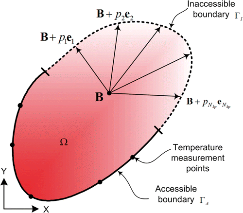
Consider a general steady-state conduction heat transfer occurred in a FGM defined on a bounded domain . As shown in , the domain boundary can be divided into two parts: the accessible part
and the inaccessible part
. It is assumed that Robin boundary condition is applied on these boundaries. Therefore, the temperature field
satisfies the following governing equation and boundary conditions,
(1)
(2)
(3)
where
is the thermal conductivity of the media,
,
,
and
the boundary condition constants on the accessible and inaccessible boundaries, respectively, and
the unit outward normal vector to the boundary. For direct problems, the geometry of the domain is assumed to be known, i.e. the shape of the boundary
is specified. In this case, the temperature distribution over the entire solution domain can directly be determined. In the IGPs, the shape of the boundary
is unknown a priori and must be determined using extra temperature measurements on the accessible part of the boundary. The over-determined boundary conditions are specified as:
(4)
where
is the measured temperature at the measurement points
and
the total number of measurement points.
In order to obtain an approximate solution, the unknown boundary is parameterized by a set of
shape parameters and a solution is pursued in a finite dimensional parameter space. Each distinct point in this parameter space represents a candidate shape for
. A forward problem can then be solved to obtain the corresponding temperature field. Therefore, the shape identification problem given by Equations (1)–(4) can be reformulated as an optimization problem. In other words, the inverse problem can be redefined as a problem of finding the shape parameters in such a way to minimize the differences between measured and computed temperatures. To do this, the following objective function
must be minimized with respect to the shape parameters.
(5)
where
and
are the measured and computed temperatures at
th measurement point, respectively.
In this study, the unknown boundary is approximated by a cubic spline to form a smooth boundary. As shown in , the location of the spline nodes can be determined using a base points and a set of direction vectors
as
(6)
where
is the number of key points and
the distance of the
th key point to the base point
. Therefore, the unknown boundary
is parameterized by a set of
shape parameters. These parameters can be arranged as the following unknown shape parameter vector
.
(7)
3. Smoothed fixed grid FEM
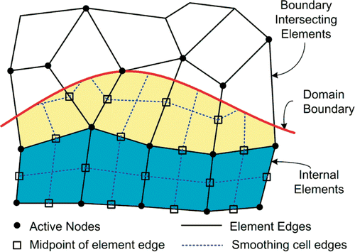
Using NBFMs, it is not necessary for the elements to coincide with the domain boundaries and therefore the boundaries can intersect the elements. A typical NBFM is shown in . The intersection of elements with boundaries causes production of three types of elements. The elements completely located inside the problem domain are the IE, those completely located outside the problem domain are the external elements and the remaining elements are BIEs. In this article, IEs and BIEs are contributing in the solution of direct problem and are considered as active elements. The nodes located on the active elements are also considered as active nodes. Therefore, the total number of degree of freedoms is equal to the total number of active nodes.
Figure 2. Classification of elements and nodes in a typical NBFM and construction of the smoothing cells in each element.
Using active elements, the interpolation of temperature field over the problem domain can be written in terms of temperatures at the active nodes as:
(8)
where
is the shape function vector and
the nodal temperature vector of the active nodes.
Differentiating this equation, the temperature gradient vector can be obtained as:
(9)
where
is the gradient matrix. Construction of gradient matrix
in the standard FEM requires direct differentiation of shape functions and leads to the domain integrals in the formulation of element matrices. In the SFGFEM, the gradient smoothing technique is used for evaluation of the field variable gradient. In this approach, each element is divided into some smoothing cells and the gradient of field variable in each smoothing cell is obtained using a smoothing operator Citation16. The smoothing cells of IEs and BIEs are schematically presented in . Considering
as the gradient of approximated temperature field, the smoothed temperature gradient in smoothing cell
denoted by
can be defined as:
(10)
where
is the domain of smoothing cell
and
the smoothing kernel defined for cell
. Integration by parts for the right side of Equation (10) leads to:
(11)
where
is the boundary of smoothing cell
and
the unit outward normal vector on
. A piecewise constant smoothing kernel is applied here which is assumed to be constant within cell
and vanish somewhere else,
(12)
where
is the area of the smoothing cell
. Substituting Equation (12) in Equation (11), the smoothed temperature gradient over smoothing cell
is obtained as:
(13)
It should be noted that the proper choice of smoothing kernel makes it possible to obtain the gradient of the field variable via a line integration along the edges of smoothing cell. Substituting Equation (8) in Equation (13), the smoothed temperature gradient at smoothing cell can be presented as:
(14)
(15)
where
is the smoothed gradient matrix.
Now, converting the differential equation and boundary conditions given in Equations (1)–(3) to the integral week form, introducing the interpolation equations (8)–(9) and using the Galerkin method Citation19, the discrete form of governing equations can be represented as:
(16)
where we have:
(17)
Construction of the conductivity matrix in Equation (17) requires integration over the problem domain
. This integration can be divided into two parts: integration over the entire IEs and integration over the internal parts of BIEs. In each IE or BIE, the integral is also broken down to the integrals over the smoothing cells. In other words:
(18)
where
and
are the domain and the internal part of Sth smoothing cell of ith IE, respectively.
Assuming constant thermal conductivity in each smoothing cell and noting that the smoothed gradient matrix is a constant matrix within each smoothing cell, the above equation reduces to:
(19)
For simplicity, the thermal conductivity of the media denoted by is considered constant in each smoothing cell and is evaluated at the centroid of the smoothing cell
. This approach has several advantages. The most interesting one is that the area integrations over the elements will convert to the line integrations along the smoothing cell boundaries. This is important in the context of NBFMs where the internal part of BIEs usually has a general polygonal shape. The other advantage is the less sensitivity with respect to geometric shape of the elements, because no geometric mapping for integration is used Citation11.
Other integrals in Equation (17) are line integrations over domain boundaries and can easily be obtained numerically by one-dimensional Gauss quadrature method.
4. Shape sensitivity analysis and optimization
As stated before, the IGPs can be transformed into an optimization problem where the objective function is given by Equation (5). In this article, a mathematical programming approach based on the conjugate-gradient method is used for this purpose. To evaluate the sensitivity of the temperature field with respect to the perturbation of the ith shape parameter , one can differentiate Equation (5) with respect to the shape parameter
as follows,
(20)
where is referred as the shape sensitivity coefficients of the computed temperature at jth measurement point with respect to ith shape parameter. Using a semi-analytical method Citation15, differentiation of Equation (16) with respect to shape parameter
leads to:
(21)
The above system of equations should be solved to obtain the temperature sensitivity . It should be noted that the solution of Equation (21) only consists of back substitution process because the nodal temperature vector
has been previously obtained and the coefficient matrix
has been previously factorized in the solution of direct problem. The terms
and
are also vanish because the accessible surface of the object is fixed. To evaluate the sensitivity of the loading vector
, defining a local coordinate system along the boundary
in each BIE and using a coordinate transformation between the local and global coordinate systems, the loading vector
in Equation (17) can be written as:
(22)
where
is the length of the segment of the boundary which is located in the Sth smoothing cell of jth BIE. Differentiating Equation (22) with respect to the shape parameter
, we have:
(23)
Using the similar procedure, is obtained as:
(24)
The integrals in Equations (23) and (24) can be evaluated using Gauss quadrature formula.
To find the derivative of the conductivity matrix with respect to shape parameter
, we use the finite difference method. Introducing a shape perturbation
to the shape parameter
, defining shape perturbation vector
and using the central difference approach, we have:
(25)
where
are the conductivity matrices for the perturbed domains
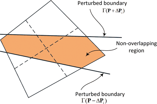
. A schematic representation of these perturbed boundaries is shown in . Substituting
from Equation (17) into Equation (25), we have:
(26)
Figure 3. Perturbed boundaries and non-overlapping regions in a BIE used in the shape sensitivity analysis.
Since the integrals of the perturbed domains and
, will cancel each other out over the overlapping regions, the evaluation of
consists only integration over non-overlapping region:
(27)
A portion of this non-overlapping region is also shown in . Finally, Equation (26) can be written as
(28)
where
represents the correct sign according to Equation (26). shows a BIE where the boundaries of the perturbed domains are passed through it. The integrals over
can be evaluated by integration over the area between these boundaries and using the gradient smoothing technique. Therefore, the area integral of Equation (28) is transformed to line integration along the edges of smoothing cells. Equation (28) reduces to:
(29)
where the correct sign for each smoothing cell is represented by
. After calculating
, Equation (21) can be solved to obtain the temperature sensitivities. Then using Equation (20), the shape gradient vector
of the objective function
can be determined by:
(30)
In this study, the unknown shape parameter vector is updated in each iteration using the conjugate-gradient method,
(31)
where
and
are the search direction and the step length of
th iteration, respectively. Let the first search direction as the steepest descent direction
. In the conjugate-gradient method, the search direction
of successive iterations is expressed as Citation15:
(32)
In this article, the optimal step length is obtained using a one-dimensional search algorithm based on the golden section search and polynomial interpolation Citation15.
5. Numerical examples
In this article, some numerical examples are solved to examine the capabilities of the proposed method. In these examples, IGPs of FGMs are solved via the SFGFEM and results are compared with exact ones. To solve these examples, only one NBFM is used for temperature and sensitivity analysis in the different iterations without any mesh adaptation or remeshing.
5.1. Example 1
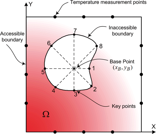
In the first example, consider a square two-dimensional object of edge length 1.0 with an unknown cavity inside, . A convective boundary condition is assumed on the external boundary with = 10.0 and
= 0.0. A uniform heat flux of
= 100.0 is also assumed on the internal surface of the cavity. Therefore, the boundary condition constants are presented as follows.
(33)
In addition to the above boundary conditions, the temperatures are also measured on 12 extra measurement points on the external surface, as shown in . The coefficient of thermal conductivity is assumed as . A NBFM with
regular elements is used for the solution of forward problem.
Practically, the temperatures in the measurement points must be obtained from a laboratory test. In this article, the measured temperatures are obtained via a numerically simulated experiment by applying a standard finite element analysis to obtain temperatures at the measurement points.
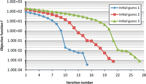
In the minimization of the objective function of Equation (5), the mathematical programming approaches such as conjugate-gradient method, generally tend to provide a local minimum. To show the applicability of the proposed method, a test case is considered and a circular cavity is identified using three different initial guesses. The initial guesses, history plot of the cavity shapes in different iterations and number of iterations needed to obtain the final shapes are given in . The variation of the objective function with respect to iteration numbers is also presented in . It is found from this example that the different choices of initial guesses do not have significant effects on the shape identification process and the identified shapes are in good agreement with exact shapes.
In the next cases, the effects of cavity shape are investigated. For this purpose, three different cavities are identified and exact and identified shapes are presented in . It can also be seen that the shape identification algorithm can detect the correct shape of the cavity.
5.2. Example 2
In the second example, consider a pipe with circular cross-section which is covered with a thick FGM layer with unknown thickness. A schematic representation of the problem is shown in . The radius of the pipe is selected as 1.0 and it is assumed that convective heat transfer occurred on the internal surface of the pipe ( = 1.0,
= 0.0) and on the external surface of the FGM layer (
= 1.0,
= 100.0). Therefore, boundary condition constants are presented as follows.
(34)
Figure 8. A circular cross-section pipe covered by a thick layer of FGM with unknown external surface ().
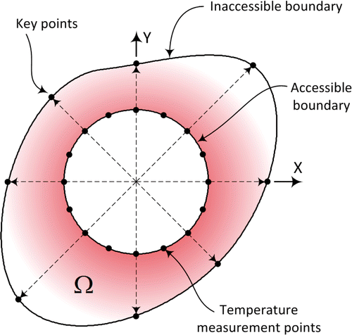
It is also assumed that the internal surface of the pipe is accessible and its temperature is measured on 16 distinct point on the internal surface temperature of the pipe. The thermal conductivity of the FGM layer is selected as and the objective is to estimate the geometric shape of the external surface of the FGM layer (inaccessible part of the boundary) via the measured temperatures on the internal surface of the pipe.
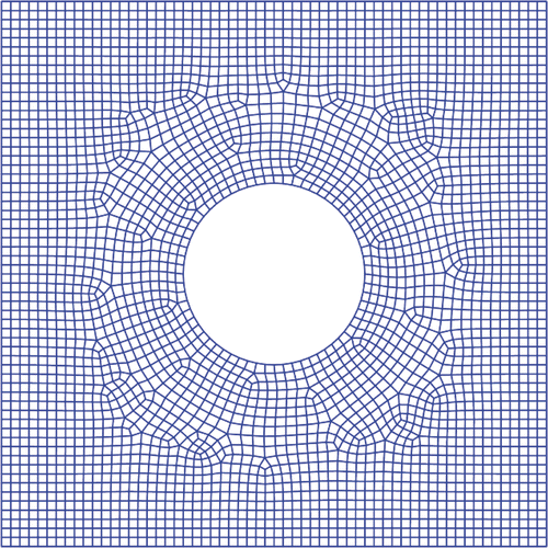
A closed spline with eight nuts is used for boundary parameterization. As shown in , the base point is positioned on the centre of the pipe and is considered fixed. The direction vectors are spaced with equal angle of 45°. The measured temperatures are also obtained via a numerically simulated experiment instead of a laboratory test. In this example, to demonstrate the stability of the proposed method with respect to the measurement errors, some random errors are also introduced in the temperature values. The amplitude of these random errors is selected as 2% and 4% of the average values. A fixed NBFM is used to solve the IGP and is shown in . Although it is not necessary, the mesh is generated in such a way that it conforms to the accessible part of the boundary.
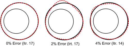
Three different cases are considered. In the first case, the shape of the external surface of FGM layer is selected as a circle of radius 1.5 centred at (0.25,0). The measurement error levels are selected as 0%, 2% and 4%. The IGP is solved and the shape of unknown boundary is obtained. The exact shapes and the approximated ones are presented in for different error levels. As this figure shows, the algorithm captured the unknown shape in different errors. It should be noted that no instability is observed in the solution process in spite of introducing the measurement error.
Figure 10. Shape identification of the FGM layer with circular external surface and different measurement errors.
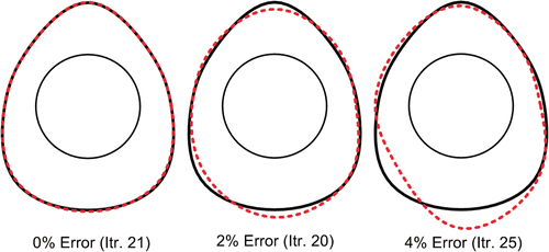
In the second case, the external surface is selected as an egg-shaped boundary whereas other parameters are selected similar to the first case. The problem is solved and the exact and approximated shapes are presented in for different error levels. As it can be seen from this figure, the approximated shapes are in good agreements with the exact solution without any instability in the solution process.
Figure 11. Shape identification of the FGM layer with egg-shaped external surface and different measurement errors.
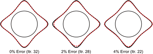
Finally in the third case, the external surface is selected as a star shaped boundary. The material property and boundary conditions on the external surface are similar to the previous cases except that a constant heat flux of is considered on the internal surface of the pipe. Three different error levels are also considered and the problem is solved. The exact shape and the approximated ones are presented in . As it can be seen, the results are in good agreements with the exact shapes and there was no instability in the solution process.
6. Conclusion
In this article, the inverse geometry shape identification problem of FGMs in the finite bodies with convective and heat flux boundary conditions were considered. The system identification scheme was based on the minimization of the squared differences between the measured and the calculated temperatures at some observation points. The boundary parameterization technique was utilized to manipulate the variation of the domain boundary during the iterative process. The optimization was performed by a mathematical programming approach using the conjugate-gradient method. In this study, the new SFGFEM approach which is based on the NBFMs was used for the solution of direct problem. In this method, a new integration scheme based on the gradient smoothing technique is used for the formulation of BIEs. The SFGFEM was also effectively used for the shape sensitivity analysis of temperature field using the semi analytic direct differentiation method. In this approach, the mesh modification (or remeshing) is eliminated completely in the direct problem or shape sensitivity analysis. Some numerical examples were solved and the validity and the effectiveness of the proposed method were examined. In these examples, the effects of different initial guesses, different measurement errors and different boundary shapes on the solution of inverse shape identification problem of FGMs were examined and the results were compared with the exact ones. It is believed that the use of the NBFMs simplified the forward and sensitivity analysis of variable domain problems and provides an effective engineering tool in IGPs of FGMs.
References
- Tikhnov, AN, and Arsenin, VY, 1977. Solution of Ill-posed Problems. Washington, DC: V.H. Winston; 1977.
- Su, CR, and Chen, CK, 2007. Geometry estimation of the furnace inner wall by an inverse approach, Int. J. Heat Mass Transfer 50 (2007), pp. 3767–3773.
- Birman, V, and Byrd, LW, 2007. Modeling and analysis of functionally graded materials and structures, Appl. Mech. Rev. 160 (2007), pp. 195–216.
- Huang, CH, and Shih, CC, 2006. A shape identification problem in estimating simultaneously two interfacial configurations in a multiple region domain, Appl. Therm. Eng. 26 (2006), pp. 77–88.
- Mera, NS, Elliot, L, and Ingham, DB, 2004. Numerical solution of a boundary detection problem using genetic algorithms, Eng. Anal. Boundary Elem. 28 (2004), pp. 405–411.
- Minutolo, V, Ruocco, E, and Ciaramella, S, 2009. Isoparametric FEM vs. BEM for elastic functionally graded materials, Comput. Model. Eng. Sci. 41 (2009), pp. 27–48.
- Lee, HS, Kim, YH, Park, CJ, and Park, HW, 1999. A new spatial regularization scheme for the identification of the geometric shape of an inclusion in a finite body, Int. J. Numer. Methods Eng. 46 (1999), pp. 973–992.
- Garcia, MJ, and Steven, GP, 1999. Fixed grid finite elements in elasticity problems, Eng. Comput. 16 (1999), pp. 145–164.
- Daneshmand, F, and Kazemzadeh-Parsi, MJ, 2009. Static and dynamic analysis of 2D and 3D elastic solids using the modified FGFEM, Finite Elem. Anal. Des. 45 (2009), pp. 755–765.
- Bendsoe, MP, and Kikuchi, N, 1988. Generating optimal topologies in structural design using a homogenization method, Comput. Meth. Appl. Mech. Eng. 71 (1988), pp. 197–224.
- Liu, GR, Dai, KY, and Nguyen, TT, 2007. A smoothed finite element for mechanics problems, Comput. Mech. 39 (2007), pp. 859–877.
- Strouboulis, T, Copps, K, and Babuška, I, 2001. The generalized finite element method, Comput. Meth. Appl. Mech. Eng. 190 (2001), pp. 4081–4193.
- Sukumar, N, Chopp, DL, Moes, N, and Bclytsohko, T, 2001. Modeling holes and inclusions by level sets in the extended finite element method, Comput. Meth. Appl. Mech. Eng. 190 (2001), pp. 6183–6200.
- Luft, B, Shapiro, V, and Tsukanov, I, , Geometrically adaptive numerical integration, Proceedings of 2008 ACM Symposium on Solid and Physical Modeling, Stony Brook, NY, June (2008), pp. 147–157.
- Haftka, RT, and Gurdal, Z, 1992. Elements of Structural Optimization. Amsterdam: Kluwer Academic; 1992.
- Kazemzadeh-Parsi, MJ, and Daneshmand, F, 2009. Solution of geometric inverse heat conduction problems by smoothed fixed grid finite element method, Finite Elem. Anal. Des. 45 (2009), pp. 599–611.
- Kazemzadeh-Parsi, MJ, and Daneshmand, F, 2010. Cavity shape identification with convective boundary conditions using non-boundary-fitted meshes, Numer. Heat Transfer, Part B: Fundam. 57 (2010), pp. 283–305.
- Kazemzadeh-Parsi, MJ, and Daneshmand, F, 2012. Unconfined seepage analysis in earth dams using smoothed fixed grid finite element method, Int. J. Numer. Anal. Meth. Geomech. 36 (2012), pp. 780–797.
- Reddy, JN, 2006. An Introduction to the Finite Element Method. New York: McGraw-Hill; 2006.
