Abstract
A mathematical model of the well resistivity-sounding problem is investigated. The model leads to an inverse problem of identification of the unknown coefficient (conductivity) in an elliptic equation in R2 inside a cylinder. The forward problem is formulated as a mixed BVP in axisymmetric cylindrical coordinates. Measured data along the axis of the well are assumed to be available. Owing to the ill-conditioned nature of the inverse problem, a logarithmic transformation is applied to the unknown coefficient, and the inverse problem is studied as a minimization problem for the residual functional. For the radial electrical-sounding case, an effective numerical method is proposed for interpreting the data of a well sounding. The method is implemented for realistic conductivity distributions, with both noise-free and noisy data.
1. Introduction
The theory of coefficient inverse problems is one of the most active areas of applied mathematics, with many practical applications. One of the most well-known applications is the electrical impedance tomography used in medicine, geophysics and defectoscopy. A review of the literature in this field of research can be found in Citation1. Kaufman and Dashevrky Citation2 provide an introduction to the basic principles and techniques of well electromagnetic sounding. Different electromagnetic sounding tools are considered by various authors. For instance, in Citation3,Citation4 the problem was formulated for an inductive logging tool. In the present work, we consider the problem of well sounding using the resistivity method. The original formulation of Langer Citation5 is regarded as the classical statement of the resistivity-sounding problem. The Langer model assumes a vertical electrical sounding where the electrical properties of the medium depend only on the depth, and a source electrode is placed on the surface of the medium. Tikhonov Citation6 also studied this model, and strictly proved the uniqueness of the solution to the inverse problem. This problem is a classical example of a coefficient inverse problem that is exponentially ill-posed Citation7. The general principles of the solution of problems of this kind, including quasisolution and regularization methods, are described in Citation8,Citation9. The first complete statement of the coefficient inverse problem (CIP) for an elliptic equation and elliptic system of equations is presented in Citation10,Citation11.
The first successful attempt at a numerical solution of the problem posed in Citation5,Citation6 is briefly described in the unfinished research of Alekseev et al. Citation12. These authors employed a regularization method, then smoothed the solution for each iteration step and obtained some examples of recovery of the unknown coefficient. In Citation13 we solved the problem numerically for various assumed conductivity distributions. Unlike Alekseev et al. Citation12, we do not use regularization of a residual functional, or a smoothing procedure. Instead, we use a two-stage procedure to recover the unknown coefficient Citation13, leading to a successful numerical solution of the considered inverse problem. In the first step, we recover a logarithmic derivative, p(z), of an unknown conductivity σ(z). In the second step, the function σ(z) is found using an analytical formula. The properties of the corresponding residual functional have been analysed in Citation14,Citation15 and established that the functional gradient is Lipschitz and satisfies a unilateral convexity condition. In this article, we also consider the problem of resistivity-sounding using a direct current.
The novel aspect of this article is the application of the method of Mukanova and Orunkhanov Citation13 to the well logging problem when the electrical properties of the medium depend only on the distance to the polar axis and do not depend on the depth. In addition, whereas the previous papers Citation5,Citation6,Citation12–15) consider the case where the source electrode is placed on the surface of the vertical layered media, we assume that the current source is placed inside a well and that the surrounding media are cylindrically layered. We express the problem in cylindrical coordinates (r, ϕ, z) and use a statement of the forward problem described in Citation16. This statement differs from the classical treatment of Citation5,Citation6 in both the boundary conditions and the geometry of the physical domain.
Well logging has been studied extensively in the Oil and Gas industry since the 1940s Citation17–22. Archie Citation17 demonstrated for the first time how the electrical log can be used to provide qualitative indications of the presence of oil and gas reservoirs. In Citation18, the spontaneous potential well logging inverse problem is formulated as a variational problem for an elliptic equation, in which the resistivity of the objective layer appears as a coefficient. The existence of solutions to the model is then proven, and sufficient conditions to ensure the uniqueness of the solution are obtained. The numerical solutions to the direct problem have been considered by many authors for different well logging tools (see, for instance, Citation19–22 and references therein).
This article is organized as follows. In Section 2, the problem is stated and the residual functional is constructed. In Section 3, the formula for the gradient of the functional is derived. The results of computational experiments with a specific noise model are presented in Section 4.
2. Statement of the problem
Assume that the conductivity of the medium in a well is a known constant, σw =const, and let rw be the radius of the well. Suppose that the well is surrounded by a penetration zone, rw ≤ r ≤ re, in which the conductivity of the medium changes continuously in the radial direction. Outside the penetration zone, the environment has another known and constant conductivity, σe =const for r > re.
For convenience, we introduce a number of dimensionless variables. Let the well radius rw be the unit of length, and let the unit of conductivity be σw. Let the current source be placed at the origin, with current amplitude I. We take(1) to be the unit of electric potential. Then the dimensionless conductivity function can be written as
where r1 = re/rw and σ∞ = σe/σw. The commonly used mathematical model of the resistivity sounding is the equation for the electric field potential. In the cylindrically symmetric case, it can be expressed as
(2) for as
(3) for 1 < r < r1, −∞ < z < ∞, and {0 < r < 1} ∪ {r > r1}, −∞ < z < ∞. Here, the function U(r, z) is the dimensionless field potential and should vanish at infinity. Additional boundary conditions should express the continuity of the potential U(r, z) and the current density σ(r)∂U/∂r at the boundaries r = 1 and r = r1. We will derive these boundary conditions later.
Let W(r, s) be the Fourier transform of the electric potential U(r, z) with respect to z:(4) Then
(5) We introduce the notation
(6) where σ(r) ∈ C2[1, r1], 0 < σ1 ≤ σ(r) ≤ σ2 < ∞, is a conductivity function. Then, the transformed governing equation is the following ordinary differential equation with parameter s:
(7)
Boundary conditions for Equation (7) were first derived in Citation16. As this reference is not readily available to most readers, we outline the proof here.
In the region where the conductivity function is constant, i.e. for r ∈ (0, 1) and r ∈ (r1, ∞), the function W(r, s) is a solution of the modified Bessel equationwhose general solution can be expressed in terms of modified Bessel functions of the first and second kind of order zero:
(8) We first construct the solution inside the well. Suppose that the solution is just the potential of a point source in a small region around the origin and can in general be expressed in the form
(9) where the function Φ(r, z) is bounded, vanishes as z → ∞, and has a well-defined Fourier transform (with respect to z). From the formula
that holds for Bessel functions and Equation (8), we find that inside the well, the function W(r, s) can be written as
(10) We next derive the boundary conditions at r = 1. The continuity conditions for the potential and current can be expressed in terms of the function W(r, s) as
(11) and
Eliminating A(s) from the previous two expressions, we obtain the following formula:(12) From the properties of the Bessel functions, we have
(13)
Now, we obtain boundary condition at the boundary r = r1. By the condition that W(r, s) vanishes at positive infinity for r > r1, the coefficient A(s) in Equation (8) must vanish, and we havefor r > r1. The continuity conditions at r = r1 can be written as
and
By eliminating B(s), we obtain
(14)
From Equations (13) and (14), with an obvious change in notation, we obtain(15)
(16) where the functions
(17) are defined in terms of the modified Bessel functions K1, K0 and I0. Equations (7), (15) and (16) comprise the forward problem, where the conductivity function is known. In the statement of the inverse problem, we suppose that the electrical properties of the medium outside the well are unknown but that we have an additional information: we assume that the potential can be measured on the axis of the well.
We now proceed to describe our model of the measured data. Let(18) be the Fourier transform of the function Φ(0, z) in Equation (9).
Using Equations (9) and (18), we express the measured potential on the well axis as(19)
Then, the function ψ(s) can be evaluated using the inverse Fourier transform:(20) By Equation (11), the solution to Equation (7) on the well boundary is given by
(21)
The inverse problem is formulated as follows:
Find the function σ(r) ≡ a(r)/r using the solution of the BVP stated in Equations (7), (15) and (16), satisfying the additional condition (21), where the function ϕ(s) is given.
We have thus reduced the inverse problem to Equations (7), (15)–(16) and (21), which coincide with the solution in Citation13 except our different boundary conditions. We can therefore apply the same numerical method used in Citation13.
3. The gradient of the residual functional
As in Citation13, we introduce the logarithmic derivative of the coefficient in Equation (7):(22)
Let(23)
be the residual functional, where 0 ≤ s1 < s2 < ∞. We construct a quasisolution to Equations (7), (16) and (21) by minimizing the functional (23) with respect to the function p(r) Citation9.
However, we cannot apply the method of Citation13 directly because we need the formula for the gradient of the functional (23). We presently derive the formula for the gradient and then apply the gradient method to find the minimizer of the functional. We express Equation (7) in terms of variations:(24)
Multiplying both sides of Equation (24) by W and using the identitieswe obtain
Integrating this equation over the range (1, r1), we obtain(25)
Multiplying (7) by δW, we have s2aWδW = a′W′δW′ + aW″δW. Substituting this expression into (25) and integrating, we obtain(26)
Using the boundary conditions (15) and (16) and the equality δa(1) = 0, we have(27)
As a(1) = 1 in dimensionless variables,(28)
It follows from the definition (22) that(29)
Substituting the last expression into (28) and changing the integration order, we obtain(30)
Multiplying (7) by W and integrating over the range (t, r1), we have(31)
Using (31), expression (30) reduces to(32)
Varying expression (23) and using (32), we obtain
Finally, we obtain the gradient formula(33)
This last expression is similar to the one given in Citation13–15. The difference is in the weighting coefficient l−1(s). Equation (7) and the coefficient restrictions are the same as in Citation13–15. Only the boundary conditions are different. We can therefore expect that the theoretical conclusions obtained in Citation14,Citation15 are also correct for the case considered here. However, this consideration is beyond the scope of this article.
4. Computational experiments and their interpretation
4.1. The solution to the direct problem and synthetic data generation
To generate synthetic data ϕ(s), we provide the function σ(r) and solve Equations (7), (15)–(16) with a(r) = rσ(r). We therefore need to define the range of s values. We first performed a series of numerical experiments with different ranges of s ∈ [s1, s2]. When we use a range with s1 < 0.5, we encounter numerical instabilities, while large values of s2 require more grid points for s and are more computationally expensive. Our numerical experiments have demonstrated that the interval s ∈ [s1, s2], with s1 = 0.8, s2 = 5 is admissible for most of the considered σ(r). To test our solution of the inverse problem, we recover the function σ(r) as if it were unknown. In all cases, we use the value r1 = 3 and solve the problem on the interval r ∈ [1, 3].
We solve the forward problem, Equations (7), (15)–(16), using the finite difference method (FDM) on a uniform grid, ri = 1 + hi, h = (r1 − 1)/Nr, i = 0, … , Nr.
The values of a(r) = rσ(r) correspond to the points ri+1/2. Equation (5) is approximated by the finite difference scheme(34) and the boundary conditions are approximated by the expressions
(35)
Equation (22) is replaced with its finite-difference analogue(36)
4.2. A gradient method algorithm
We solve the inverse problem using the following iterative algorithm Citation23:
| i. | Specify the value of ϵ used in the termination criterion (see below); choose an initial guess p(0)(r) = ln(rσ(0)(r))′. | ||||
| ii. | Find the new values of p and q using the conjugate gradient method formulas: | ||||
| iii. | Repeat step (ii) until the following termination criterion is satisfied: | ||||
4.3. Noise simulation
To assess the efficiency of our algorithm, we add stochastic noise to our input synthetic data. In practice, we cannot measure the potential function in the vicinity of the source point and must therefore extrapolate the potential using the function 1/z near the source electrode. This process produces an error in the value of σ(1) = σw of the conductivity inside the well. It has been shown in Citation13 that this noise can be simulated by adding a constant δ1 to the transformed output data. The influence of this kind of noise has been studied in detail in Citation13. There is an additional noise contribution from measurements of the potential function. We assume that this noise can be represented as a linear combination of harmonics with random amplitude:(40)
Here, zmax is the maximum coordinate where the potential can be measured, and coefficients ak, k = 1, … , m are assumed to be random variables uniformly distributed on the interval [−δ, +δ]. The noise model therefore depends on three parameters: the number of random variables, m; the scale length, L and the maximum amplitude of the random data, δ. The number m depends on a measurement and is limited by some frequency filter. To choose admissible noise parameters, we calculate the function W(1, s) for a sufficiently wide range of the parameters and compute the potential u(z) numerically, using Equations (20) and (21):(41)
We tried different values of smin and smax and found the values smin = 0.05, smax = 10 to be admissible to calculate the improper integral in (41). The function W(1, s) was evaluated on a logarithmic grid with 256 points.
We then added the noise given by (40) to the function u(z). We specify the noise level through the parameter(42)
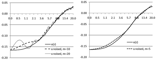
Graphs of the noisy potential are shown in Figure for various values of the noise parameters. The preliminary measurements are pre-processed; therefore, cases like those presented in the left-hand panel of Figure are unlikely to occur in practice. A more realistic noisy potential function is presented in the right-hand panel of Figure with m = 5, L = 1, δ ∼ 0.001 and zmax = 5.
In our numerical simulations, we first compute the noise-free function ϕ(s) = W(1, s) and then we analytically calculate the Fourier transform of the noise, χ(z). By Equations (20) and (21), we have:(43)
Here, the range smin, smax of the parameter s is taken to be the same as in Equation (41). The function ω(s) is used to set the termination criterion for noisy data in Equation (39).
4.4. Numerical results
In all of the numerical tests described below, we take r1 = 3, s1 = 0.8, s2 = 5 and noise parameters m = 5, L = 1, and zmax = 5. We set the tolerance ζ on αn, defined by Equation (38), equal to 10−8.
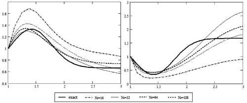
We have first tested the algorithm for different numbers of grid points, Nr = 16, 32, 64, 128, with the results shown in Figure . One can see that a finer grid gives superior results. All the results in Figure were obtained with ‖∇J‖ ≤= 1.5 × 10⁻⁵, and corresponding values of the residual depend on the grid point numbers and vary from 5 × 10⁻⁵ to 3 × 10⁻⁸. We also varied the number of grid points in s, Ns = 32, 64, 128, with results similar to those shown in Figure
Most of our numerical simulations were performed with Nr.s = 64 grid points in both r and s. Our simulations show that the termination criterion ϵ ∼ 5 × 10⁻⁵ is admissible with this number of grid points. Our numerical experiments suggest initialising the iterations with a very small αn ∼ 10−5 and then setting the value of αmax automatically in subsequent iterations using the empirical condition: max|∇J| × αmax = 1.
We generate synthetic data σsynth(r), r ∈ [1, 3], according to the equation:
We can explore various forms of σ(r) by varying the parameters A1, A2, c0, c1, and ϑ.
Our computations show that the conditions under which the solution can be obtained numerically are similar to those described in Citation13. In particular, we recover the conductivity function with satisfactory quality for contrast ratio amax/amin up to 10 and for simple distributions of σ(r). The results of our numerical reconstruction with noisy and noise-free data for a few forms of σ(r) are shown in Figures The relative errors δ ≔ ‖σexact − σrecov‖/‖σexact‖ in C-norm and the corresponding number of iterations are given in Table . In all cases, we stop the iteration process when criterion (39) is satisfied. In most of the cases we considered, the residual functional and its gradient decline too slowly when ϵ < 5 × 10⁻⁵, and the number of iterations therefore increases sharply. However, the increased number of iterations does not yield significant improvement of the solution.
Figure 3. Data interpretation for the monotone conductivity function with a contrast ratio equal to 10.
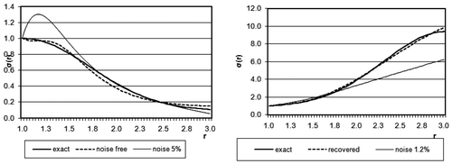
Table 1. Relative errors δ in C-norm and corresponding iterations number.
The number of iterations required before the termination criterion is satisfied depends on σ(r). In most cases, it varies from 200 to 15,000. More acceptable results are obtained for the cases where σ(r) is monotonic. Figure shows the results for noise- free and noisy data with contrast ratio equal to 10. When σ(r) is decreasing, the quality of the reconstruction remains fairly high up to a noise level of 5%. However, when σ(r) is increasing, we only obtain satisfactory results up to a noise level of 1.2%. The case where σ(r) has a local maximum near the well zone is also favourable; the results for this case are presented in the left-hand panel of Figure . In this case, acceptable results are obtained for contrast ratios above 2.5 and noise levels up to 2.5%.
Figure 4. Data interpretation for a conductivity function maximum and minimum near the well zone, at the distance equal to 0.4.
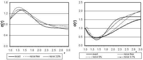
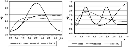
The most unfavourable case occurs when the conductivity has a local minimum near the well zone. The reason for this is an ‘overshadowing’ effect. The zone with low conductivity is located in a valley between two zones with higher conductivity, so that very little current reaches the distant areas. The impact of the distant areas in the output data on the well boundary is negligible, and the residual functional is therefore insensitive to variations in the conductivity of these areas. As shown in table 1, line 4, a large number of iterations is required to reach the termination criterion because of this effect, and it also produces high relative errors. However, in the nearest zone, for 1 ≤ r ≤ 1.5, the quality of the reconstruction is high enough (see, for instance, the last line of Table ). The cases with distant local extremums of the function σ(r) are also unfavourable, as are cases with two or more extremums. The results are shown in Figure (right) and Figure . In these cases, the reconstruction quality was admissible as long as the distance to the well boundary was less than 0.5, i.e. for r ≤ 1.5. The influence of the distance on the quality of the reconstructed conductivity function can be seen in Figures and . These figures show the deterioration in quality at large distances.
Figure 5. Data interpreation for a conductivity function having distant maximum and for a wavy conductivity distrbution with different noise level.
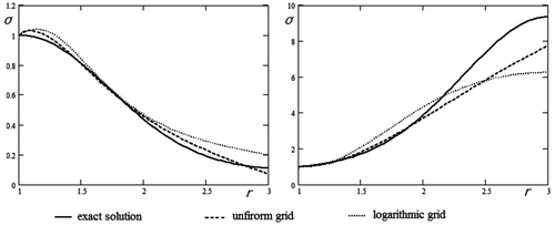
We attempted to improve the quality of the recovered data with a logarithmic grid for the solution of the direct problem (7)–(16). We applied the transformation of variables q = ln(1 + r) and then proceeded to solve the problem numerically. However, we did not achieve any significant improvement of the numerical solution using this technique. The results obtained using a uniform and a logarithmic grid are compared in Figure .
5. Conclusions
We have reduced a mathematical model of a cylindrical well resistivity-sounding to one of a vertical electrical sounding (VES); the only differences are in the boundary conditions and the weighting coefficients in the gradient of the residual functional. We have applied a numerical method, which is successful in VES, to the interpretation of well resistivity-sounding data. The method has been implemented numerically for some realistic conductivity distributions. Our numerical results with noise-free and noisy data demonstrate that in some simple cases, the unknown coefficient can be accurately reconstructed near the well. However, the results obtained for the cylindrically symmetric case turn out to be significantly worse than those for a vertical layered media model, and require further improvement.
Acknowledgements
The author is grateful to professor Alemdar Hasanoglu (Hasanov) for giving attention to this work and for valuable suggestions. The author would like to thank to the referees whose comments and suggestions substantially aided this article.
References
- Borcea, L, 2002. Electrical impedance tomography: Topical review, Inverse Probl. 18 (2002), pp. R99–R136.
- Kaufman, AA, and Dashevsky, YuA, 2003. Principles of Induction Logging. Amsterdam: Elsevier; 2003.
- Pen'kovskii, VI, and Korsakova, NK, 2010. The new method of data interpretation of well electromagnetic sounding, Inverse Prob. Sci. Eng. 18 (7) (2010), pp. 983–995.
- Tabarovsky, LA, Beard, DR, and Mezzatesta, A, 1994. Induction logging: resolution analysis and optimal tool design using block spectrum analysis, Society of Professional Well Log Analysts Logging Symposium Transactions, Okla, Japan, (1994), pp. DD1–DD19.
- Langer, RE, 1933. An inverse problem in differential equations, Amer. Math. Soc. Bull. 39 (1933), pp. 814–820.
- Tikhonov, AN, 1949. About uniqueness of geoelectrics problem solution, Doklady Acad. Sci. USSR 69/6 (1949), pp. 797–800, (in Russian).
- Alessandrini, G, 1988. Stable determination of conductivity by boundary measurements, Appl. Anal. 27 (1988), pp. 153–72.
- Tikhonov, A, and Arsenin, V, 1977. Solution of Ill-Posed Problems. New York: John Wiley; 1977.
- Ivanov, VK, 1963. On ill-posed problems, Mat. Sbornik 61 (2) (1963), pp. 211–223, (103) (in Russian).
- Hasanov, A, and Mamedov, A, 1994. An inverse problem related to the determination of elastoplastic properties of a plate, Inverse Prob. 10 (1994), pp. 601–615.
- Hasanov, A, 1995. An inverse coefficient problem for an elasto-plastic medium, SIAM J. Appl. Math. 55 (1995), pp. 1736–1752.
- Alekseev, AS, Tcheverda, VA, and Niambaa, Sh, 1989. "Optimizational method for solving the inverse problem of geophysical prospecting by electric means under direct current for vertically-inhomogeneous media". In: Proceedings of the Inverse Modelling in Exploration Geophysics. Braunshweig, Wiesbaden. 1989. pp. 171–189.
- Mukanova, B, and Orunkhanov, M, 2010. "Inverse resistivity problem: Geoelectric uncertainty principle and numerical reconstruction method". In: Math. Comput. Simulation, 80 (2010). 2010. pp. 2091–2108.
- Mukanova, B, 2009. An inverse resistivity problem: 1. Lipschitz continuity of the gradient of the objective functional, Appl. Anal. 88 (5) (2009), pp. 749–765.
- Mukanova, B, 2009. An inverse resistivity problem: 2. Unilateral convexity of the objective functional, Appl. Anal. 88 (5) (2009), pp. 767–788.
- Dvoretckiy, PI, and Yarmakhov, IG, 1998. Electromagnetic and Hydrodynamic Methods in Oil and Gas Deposit Exploration. Moscou: Nedra; 1998, (in Russian).
- Archie, GE, 1942. The electrical resistivity log as an aid in determining some reservoir characteristics, AIME Trans. 146 (1942), pp. 54–62.
- Peng, Y-J, 1997. An inverse problem in petroleum exploitation, Inverse Prob. 13 (1997), p. 1533.
- Lv, W-G, Chu, Z-T, Zhao, X-Q, Fan, Y-X, Song, R-L, and Han, W, 2009. Simulation of electromagnetic wave logging response in deviated wells based on vector finite element method, Chin. Phys. Lett. 26 (2009), p. 014102.
- Geng, M, Liang, H, Yin, H, Liu, D, and Gao, Y, 2012. Numerical simulation in whole space for resistivity logging through casing under approximate conditions, Procedia Eng. 29 (2012), pp. 3600–3607.
- Epov, MI, Mironov, VL, Muzalevskiy, KV, and Yeltsov, IN, 2010. "UWB electromagnetic borehole logging tool". In: IEEE International Symposium on Geoscience and Remote Sensing IGARSS. Honolulu, Hawaii, USA. 2010. pp. 3565–3567.
- Onegova, EV, and Epov, MI, 2011. 3D simulation of transient electromagnetic field for geosteering horizontal wells, Russian Geol. Geophys. 52 (7) (2011), pp. 725–729.
- Vasil'ev, FP, 1981. Methods for Solving Extremal Problems. Moscow: Nauka; 1981.
