Abstract
This study deals with an inverse detection of stiffness degradation that occurs due to multiple cracks in bridge decks subjected to unknown moving loads. Six unknown parameters are considered to determine the damage distribution, which is a modified form of the bivariate Gaussian distribution function. The proposed approach is more feasible than the conventional element-based damage detection method from the computational efficiency because a finite element analysis coupled with a hybrid genetic algorithm using a small number of unknown parameters is performed. The validity of the technique is numerically verified using a set of dynamic data obtained from a simulation of the actual bridge modelled with a three-dimensional solid element. The numerical examples show that the proposed technique is a feasible and practical method, which can prove the location of a damaged region as well as inspect the distribution of deteriorated stiffness although there is a modelling error between actual bridge results and numerical model results as well as unknown moving loads.
1. Introduction
Civil engineering infrastructures such as a bridge deteriorate with time as a result of outdated materials, excessive use, overloading, climatic conditions, inadequate maintenance and deficiencies in inspection methods. In order to reduce the failure probability of bridges in service, the techniques assessing the condition of the bridges and detecting the overloading of moving vehicles to prevent continual growth of damage are needed. Recently, condition assessment technology and non-destructive evaluation (NDE) techniques have provided various solutions for safety of structures by means of detecting damage or defects from static or dynamic responses induced by external loading. Among many NDE methods, this study is focused on the use of dynamic response in detecting localized single or multiple cracks in bridge decks subjected to unknown moving loads. From a practical viewpoint, it is very important to detect damage in bridge decks without external loading information. For instance, at service state under passing vehicular traffic, it needs to inspect the condition of bridge damage without any information or with limited information related to moving loads to avoid traffic control. For this reason, a new method for enabling condition assessment without the information of moving loads is considered in this study. Considering the interaction forces between vehicle and bridge with the viscous damping on the Euler-Bernoulli beam model, Law et al. Citation1 identified moving loads using modal superposition principle in time domain. Moreover, Law et al. Citation2 proposed frequency time domain method by performing Fourier transformation of the load-response relationship to identify the moving load directly using least squares. Chan et al. Citation3 applied moving loads identification method based on the Euler's beam theory together with modal analysis. In addition to these methods, Steffen and Rade Citation4 used a Fourier series to identify moving load on a simply supported beam. To obtain a good quality of moving loads, Chan et al. Citation5 developed a method applicable to the prestressed concrete bridges considering the effect of the prestress on the structure. Chan and Ashebo Citation6,Citation7 identified moving loads on the continuous bridge using only a target span. Also, they found that the accuracy of the identified value of moving loads based on bending moment response is better than acceleration response. These methods, despite their improvements over analytical methods based on the closed form solution, still possess several restrictions from a numerical computation point of view, such as divergence and instability problems, during numerical calculations, and the trap of minimum especially for large and complicated structures.
Recently, direct search methods based on metaheuristics techniques and artificial intelligence, such as genetic algorithms (GAs), simulated annealing methods and neural networks have been introduced and promisingly applied to the field of structural identification Citation8. Among them, GAs attract our attention because they do not require a considerable amount of data in advance in dealing with complex problems and can make global solution search possible as opposed to classical gradient-based optimization techniques. Suh et al. Citation9 presented a hybrid neurogenetic technique that is able to identify the region and extent of damage in a beam or frame structure using only frequency information. Mares and Surace Citation10 demonstrated the ability of a GA to identify damage in elastic structures. Friswell et al. Citation11 combined the genetic and eigen sensitivity algorithms for locating the damage. Chou and Ghaboussi Citation12 proposed a GA-based method to determine the region and extent of damage in truss structures from the measured static displacements. Krawczuk Citation13 presented a wave propagation approach to detect damage in beam structures based on GA and the gradient technique. However, conventional GAs have a limit in solving inverse problems using GA because of the high computational cost of a large number of iterations: it is necessary to perform iterative forward computations for each chromosome. Thus, the total time spent in solving the forward problem could be extremely long, usually in the order of magnitude of several thousand or more depending on the complexity of the problem Citation14. Unlike these, a uniform micro GA (μGA) can avoid premature convergence, so that it can provide faster convergence to the near optimal region than a simple GA. Carroll Citation15 found that a uniform μGA is more roust in handing an order-3 deceptive function than the traditional GA methods. Au et al. Citation16 developed a natural-frequency-based μGA for detecting damage in a one-dimensional beam. Lee and Wooh Citation17 applied a μGA for detecting damage in plate structures subjected to dynamic loading. However, the numerical examples used in the studies are not practicable in that they regard damage as a predetermined rectangular element Citation18. Rus et al. Citation19 examined the identification of defects in laminated composite structures subjected to in-plane static loads using the boundary element method and μGA. They used an elliptic function with five unknown parameters to represent an arbitrary damage shape. However, this approach has several limitations such as the use of static loads, limitation to in-plane behaviours, and lack of capability to detect the extent of damage. Lee et al. Citation20 presented a method to detect stiffness degradations using a modified bivariate Gaussian function, with which it is possible to consider an arbitrary damage shape. The method has been applied to concrete plates subjected to impact loads using the finite element method (FEM) and μGA. Lately, Park et al. Citation21 proposed the damage-detection technique to determinate damage distribution, which is a modified form of the bivariate Gaussian distribution function. This method used a combination of the combined FEM and the advanced μGA and moving loads as input excitation. However, it is required the position and velocity of the moving load in advance.
In this study, the alternative damage-detection technique that can determinate degraded stiffness distribution under unknown moving loads. The proposed method uses a modified form of the bivariate Gaussian distribution function to detect degraded stiffness characteristics. In addition, an advanced hybrid GA (h-GA) is employed as an algorithm for solving the inverse problem. The h-GA can avoid premature convergence like μGA and provide faster convergence to the near optimal solution than μGA by introducing a conventional gradient-based technique that local searching power is excellent due to fast convergence. Meanwhile, a three-dimensional (3-D) solid bridge model is used for obtaining the measurement data. On the other hand, a two-dimensional (2-D) plate model is used to run an inverse procedure to obtain better computational efficiency. Thus, the approach of the present study is more similar to reality than using the same model for generating the simulated experiment and using the inverse procedure. This is because the difference of measured data due to modeling error between real bridges and numerical models can be accounted for.
The objective of this study is to present a new method for evaluating multiple cracks happened in bridge decks without the information about moving loads. In the next section, the damage model and the moving load model that can simulate cracked bridges under moving loads are formulated at the forward procedure. Then, the characteristic of h-GA and the combined algorithm of FEM and h-GA are presented at the inverse procedure. For numerical verification, six examples with different moving forces and multiple cracks are tested with dynamic data measured from a 3-D bridge model considering a realistic circumstance with model uncertainty. The numerical examples demonstrate that the proposed method has a good capability for detecting multiple cracks and evaluating overall degraded stiffness distribution in bridge decks.
2. Forward procedure
In the numerical model for forward procedure, a two-dimensional MZC (Melosh, Zienkiewicz, and Cheung) rectangular plate model is employed. The MZC rectangular element has the merit that is simple geometry and is easy to formulate.
2.1. Damage model
In a finite element formulation, the stiffness matrix of a structural system is expressed in terms of its material properties, geometry, and boundary conditions. In numerical approach for detecting damage, there are two different methods to define the damage extent. The first is the reduction of material properties (Young's modulus or Poisson's ratio) of a specific element. For example, 20% damage at an element implies that there will be 20% reduction of Young's modulus or Poission's ratio Citation22,Citation23. The other method is to define the stiffness reduction factor reflecting the severity of the damage. For example, when damage occurs in a structure, the stiffness matrix of the damaged structure can be represented as the sum of the element stiffness matrices multiplied by a reduction factor representing the damage Citation10,Citation16. Although it is not the limitation of the approach in general, we have a restricted study scope in this paper, in that the damage is defined as the stiffness reduction factor at one or more local areas. In specific, the structure is discretized into a set of finite elements categorized into undamaged and damaged states of different degradation levels.
For such a model, the global material stiffness matrix of the th-damaged element can be expressed as
(1) where
denotes the stiffness reduction factor; and
denotes the material stiffness in its original (undamaged) state. Note that the tilde (∼) symbol above a variable is used to denote the damaged state. The stiffness matrix of the damaged element in the local coordinates can now be written as the volume integral of the form
(2) where
denotes the strain–displacement matrix of the element (
); and the superscript T denotes the transpose operator. Note that
and
are a property that is independent of damage; thus it is applicable to all the elements (
), whether damaged or undamaged. For a 2-D plate model, the formulation to represent the characteristics of stiffness reduction can begin by applying the bivariate Gaussian distribution function given by
(3) where
is the determinant of the standard deviation matrix
;
is the coordinate vector;
is the mean vector; in the two-dimensional case
(4) and
is the correlation factor between
and
. Considering the distribution of stiffness reduction of a plate with the total length sizes
and
in the
and
directions, the correlation factor becomes
because the coordinates
and
are statistically independent of each other. In addition, the parameters multiplied by the exponential function in Equation (2.3) could be considered as the extent (
) of the stiffness damage at the central point of the
th-damaged element. The damage field becomes identical to the undamaged state in all elements for
. The distribution function of damage with Gaussian shape, which distributed from the central point of the
th damaged element, can be defined using Equation (2.3) as
(5) where,
(6) and the damage extent
is the value between 0 and 1; the coordinates
and
vary with the range from 0 to
and
, respectively; the mean values
and
are selected in the range from 0 to
and
, respectively; the standard deviations
and
are determined in the range from 0 to
and
, respectively; and the variables
and
are the values between 0 and 1 chosen to seize the specific shape of damage. In order to represent the stiffness reduction rotated at an arbitrary angle, the coordinate vectors
of each element rotated on the revolution point of
can be expressed using the following rotational transformation relationship:
(7) where
is the rotational matrix with the rotation angle
, that is
(8)
Note that in Equation (2.7) because the two-dimensional distribution for the stiffness reduction is only arbitrarily rotated without the movement of the coordinate of the mean vector
. In order to associate the stiffness reduction factor
in Equation (2.1) with the extent of stiffness damage
in Equation (2.5), the stiffness distribution at the arbitrary coordinates
and
in a plate is described using the relation as
(9)
The generalized stiffness distribution function is expressed in terms of independent constants by substituting Equation (2.7) into Equation (2.5) and using the relation Equation (2.9). Thus, the stiffness reduction function distributed from the central point of the th-damaged element of a plate can be expressed as
(10) where the rotated coordinates
are arbitrary as the original coordinates
. This contains the six unknown parameters, that is
(11)
The modified bivariate Gaussian function presented above is capable of an illustration of stiffness reductions in an arbitrary distribution type. However, it does not mean that it can represent directly real damage types such as cracks. The Gaussian function reflects the distribution of stiffness reductions in structures transformed equivalently from dynamic responses changed from damages.
In order to determine the stiffness reduction factor of each element, Equation (2.10) can be expressed in
th element as
(12) where
(13) and
and
denote the number of elements divided in the
and
coordinates, respectively. In the finite element formulation, the stiffness matrix of the kth damaged element in the local coordinates can now be written as the volume integral form, that is
(14) where
is the coordinate vector of
th element; and
is the stiffness matrix at the
th element of a plate. Note that
is a property that is independent of damage; thus it is applicable to all the elements (
), whether damaged or not.
The governing equation of motion of the system using Equation (2.14) is written in the form(15) where
and
are the displacement and acceleration vectors, respectively;
is the mass matrix without loss before and after damage;
is the stiffness reduction matrix; and
is the time history of the applied moving load. The damping effects in Equation (2.15) are neglected, because the damping matrix can not be constructed from element damping matrices, such as the mass and stiffness matrices of the element assemblage. In the restricted scope of our study, we focused on solving the inverse problem using the modified bivariate Gaussian distribution function.
2.2. Moving loads
For the transient analysis of a slab bridge subjected to the effects of moving loads, an implicit time integration method, called as the Newmark integration technique is adopted with the integration parameters and
, which lead to constant-average acceleration approximation. Considering a moving load with a velocity
on a plate element, the total moving distance (
) of the load at time
is given by
(16) where 1/3.6 is a velocity conversion constant which transforms km h−1 into m s−1 and
denotes the initial coordinate of the moving load in the longitudinal direction. The location number
of the element which the moving load passes through at time
can be expressed as
(17) where
(18) and
and
are the number of division elements in the longitudinal (
) and transverse direction (
),
is the initial coordinate of the moving load in the transverse direction;
and
are the length of a plate in the
and
directions, respectively; and INT() means the integer part of the value in a parenthesis.
The moving load vectors at an arbitrary location on the
th element of the plate should be inevitably distributed to the nodal loads
using the zeroth-order Hermite (Lagrange) interpolation function
. The natural coordinates
of the element for the moving load at time
can be derived as
(19)
In a four-node element with three degrees of freedom per node, the moving load distribution into four neighbourhood nodes not considering distribution of moment can be expressed as(20)
The total external force vectors applied on the plate at
can be obtained by summing up the distributed
loads as given by
(21)
In the Newmark integration scheme, the effective loads at time can be calculated as
(22)
The dynamic displacements , accelerometers
, and velocities
at time
can be solved as
(23)
(24)
(25) where the triangularized effective stiffness matrix is
; and
,
,
,
, and
are integration constants in the Newmark integration method, respectively.
3. Inverse procedure
Inverse procedure presented is to detect a distribution of stiffness reduction in a structure and to determine the damage region and its extent. Since the entire procedure is associated with FEM solvers in each iteration step, the rate of convergence is heavily dependent on the complexity level of the FEM formulation. Because of this reason, we adopt the h-GA algorithm for inverse procedure, which could significantly reduce the number of iterations and thus reduces the computation time for the calculations of FEM solvers Citation17.
3.1. Hybrid genetic algorithm
The accuracy of a system identification method applying a conventional gradient-based technique may be influenced by the insufficient initial information. That is, the trap of minima due to the incomplete initial values often occurs and this problem should be gotten over. In this study, to resolve the earlier trouble of a gradient-based technique in estimating system parameters, the advanced system identification technique applying the h-GA is employed. In general, GAs are good at global searching but slow at converging because they are necessary to perform iterative forward computations for each chromosome. On the other hand, a conventional gradient-based technique is good at local searching but lack a global search power; thus to enhance searching capability and improve convergence performance, the incorporation of a GA with a conventional gradient-based optimization technique is enough to attract attention. The introduced h-GA is such an algorithm. In addition, the h-GA can overcome a limit in solving inverse problems using a conventional GA because the high computational cost of a large number of iterations can be reduced dramatically by operating on a very small population size. The small population size very often leads to the phenomenon of the genetic drift in chromosomes in a few generations. To maintain the genetic diversity in the population, the h-GA enhances the genetic operation and search strategy.
To identify the unknown parameters such as damage characteristic of bridges accurately, the h-GA should be combined with the FEM that can reflect the change of structural properties and loading condition in bridges in the present state. In other words, the FE model parameters that can explain the change of stiffness induced by cracks in bridges under moving loads sensitively should be utilized as identification parameters in inverse procedure. In this study, to identify the damages due to single crack or multiple cracks in bridges subjected to moving loads, unknown parameters, , describing stiffness and moving loads change, will be selected adequately. For example, the following identification parameter vector with
is to estimate the local damage characteristic induced by cracks in bridges under constant moving velocity and weight:
(26) where
denotes the stiffness reduction factor;
denote the
-coordinate of the center of local damage;
denotes the measure of dispersion along the
-axis;
denotes the
-coordinate of the center of local damage;
denotes the measure of dispersion along the
-axis;
denotes the rotation angle of the centre of local damage;
denotes the weight of moving loads;
is the velocity of moving loads. In terms of the GA, the unknown parameter vector
is represented by the selected individuals on each iteration. While, dynamic analysis using the combination of FEM and h-GA can be considered as the following vector function.
(27) where Ω is the vector space of identification variables;
is the number of identification variables;
is the vector space of dynamic response such as displacements or acceleration data; N is the number of measured data used to identify a system and
are dynamic responses calculated by using the dynamic analysis combining the FEM with the h-GA from an arbitrary
. After all, identifying a distribution of stiffness reduction and moving loads become a problem finding the values distributed by the identification parameters when the measured data agree with the values of the function U. Thus, the problem for computing a distribution of stiffness reduction and a moving load is described as the following optimization problem set:
(28) where
are the measured data; and
(
) is the function satisfying
.
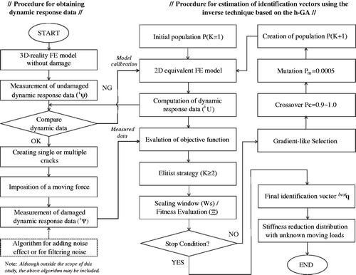
Figure illustrates a flow chart for identifying the parameters qs computed by the combination of FEM and h-GA, as applied in this study. Using the combined finite element analysis and h-GA, the central location of a damaged region due to single or multiple cracks in bridges as well as the overall distribution of deteriorated stiffness finally can be determined by investigating the unknown parameters qs.
4. Numerical examples
4.1. Numerical model
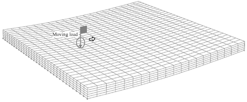
In order to consider the uncertainties between the equivalent model in forward solver and 3-D-reality, the measurement data obtained from the bridge modelled by a 3-D FE model Citation24,Citation25 shown in Figure are used in the inverse procedure for detecting the characteristic of degraded stiffness and moving loads. In addition, we consider a 2-D FE plate-like model with 400 divided elements () subjected to unknown moving loads for an efficient numerical model, as shown in Figure . As shown in the figure, the nine measurement points are used for computing the response data, which coincide with the location of sensors in a 3-D concrete slab model. The acceleration time histories during the excitation of a moving load are recorded as the sampling frequency of 100 Hz. The induced fundamental frequencies of the example structures in simulation are 13.095–13.122 Hz (first mode). It is known in general that the sampling rate is feasible for 4–20 times higher than fundamental frequencies of structure (rule of thumb). The geometrical and material properties of the 3-D model are same as those of numerical model. For a 3D-model, we choose an old reinforced concrete slab bridge named as Kirkman's Branch Bridge Citation26 built in 1941, because the NDE is necessary for deteriorating structures. The length, width and thickness of plates are 6.0, 6.0 and 0.33 m, respectively. Young's modulus, density and Poisson's ratio of concrete used are 23.0 GPa, 2300 kg m−3, and 0.167, respectively Citation26. The material properties are assumed as those of general RC structures, because the exact information of the old bridge is unknown. The loading on the deck is assumed as a concentrated load (432 and 225.5 kN) for the numerical efficiency in the inverse procedure. In implementation using the h-GA, we play with six individuals and the probability of uniform crossover was set to be 1.0. The combination of given possibilities (
) can be encoded in binary digits to form each individual. In our case, we use an individual consisting of total 68 chromosomes.
Figure 3. 2-D equivalent plate model for a concrete slab used as forward solver in inverse procedure.
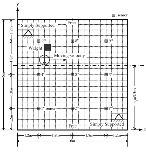
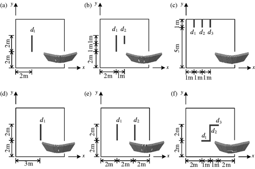
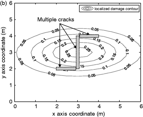
For numerical demonstrations examples having one or more cracks are considered as more realistic damage cases, as shown in Figure . Also, among the information of moving loads, the velocity () and the weight (
) are assumed to be unknown. While, the initial location (sy) of moving loads from the
-axis is assumed to be known as 3.5 m and the travelling axis of a vehicle are assumed to be parallel to the
-axis. Therefore, general identification variables used for detecting the characteristics of these damages and moving loads are given by
(29) where
denotes the velocity of a moving load;
denotes the single axle weight of a moving load;
denotes the stiffness reduction factor due to cracks; μx denote the
-coordinate of the centre of maximum stiffness reduction element; σx denotes the measure of dispersion along the
-axis;
denotes the
-coordinate of the centre of maximum stiffness reduction element; σy denotes the measure of dispersion along the
-axis; θ denotes the rotation angle of the centre of maximum stiffness reduction element;
denotes the magnitude of the
th local damages. Unlike the parameters about a moving load (v and w), the parameters about the stiffness reduction distribution (β, μx, σx,
, σy and θ) that mean independent variables of a modified bivariate Gaussian function are dependent on local damage induced by di. From the evaluation of these parameters, the physical characteristics of the local damages induced by cracks are able to be equivalently transformed into the stiffness reduction distribution of structures. With different unknown parameters in Equation (4.1) and the positions of single or multiple cracks in Figure , six examples are given as
(30)
(31)
(32)
(33)
(34)
(35) where units of
,
, and
mean km h−1, kN and crack depth-to-length ratios(%), respectively. Three moving velocities of 36.0, 54.0 and 72.0 km h−1 are employed as the study of Lee et al. Citation20 and Park et al. Citation21. They reported that it is adequate to select moving velocities between 30 and 70 km h−1, considering accuracy and the reality of controlling a vehicle. The weight of moving loads, 432.0 and 222.5 kN, are employed as the study of Lee et al. Citation20, Park et al. Citation21 and Azizinamini et al. Citation26. The weight of 432.0 kN is the concentrated truck load known as KS DB-24 and that of 222.5 kN is a single dump truck load filled with sand, weighting approximately 222.5 kN.
The example of EX6 is to describe the fact that a modified bivariate Gaussian function may be rotated with an angle of . EX1 and EX4 represent the cases with a single crack and EX2, EX3, EX5 and EX6 show the cases with multiple cracks. In this case study, we use only a single modified bivariate Gaussian function to detect the distribution of stiffness reduction of a bridge deck. Therefore, the distribution of stiffness reduction of EX1 and EX4 is expected to be localized along to a crack; that of EX3 and EX5 is supposed to be widely distributed from the centre of multiple cracks; Finally, that of EX2 and EX6 is presumed to be rotated due to unsymmetrical property of cracks.
The lower and upper bounds of identification variable is shown in Table . The bounds of velocity () and weight (
) of moving loads are selected to [30 90] km h−1 and [0 500] kN, respectively.
's bound is assigned to [0.0 0.5] that the maximum value of degraded stiffness in an element can be given until the half of the original stiffness. The bounds of
and
are selected to [0.0 6.0] m, which is a dimension of the length and width of the slab. The bounds of
and
are widely selected to [0 10] to seize the specific shape of degraded stiffness induced by prescribed single or multiple cracks. The bound of
is chosen as [0 180]
considering the symmetric property of the bivariate Gaussian function.
Table 1. Lower and upper bounds of identification variable.
4.2. Detection of parameters
The final estimated values and fitness function values of identification variables for EX1, EX2, EX3, EX4, EX5 and EX6 after 2,000 generations based on the h-GA are represented in Table with an error (%) in the parenthesis. In table, (–) means that an error does not exist. The exact values of the bivariate Gaussian function variables that can describe exactly the prescribed local damage hardly exist. Thus, the estimated stiffness reduction distribution is an approximated solution rather than the exact solution. The objective employing the bivariate Gaussian function is that the distribution of complex local damage induced by single or multiple cracks can be equivalently transformed into the stiffness reduction distribution of structures, which is an easy and useful way to evaluate the damage behaviour of structures. In this study, the characteristic of physical cracks is evaluated from the estimated Gaussian function variables. On the other hand, the properties ( and
) with respect to moving loads are exactly estimated with estimation errors less than about 2% as presented in Table . These results show that it is possible to assess the condition at bridges without information about external forces, such as a moving load.
Table 2. Final estimated values and fitness values of identification variables.
In Table , the localized damage factor () for each crack corresponding to the position containing cracks at a 3-D model and the overall damage factor (
) that can estimate the overall extent of damage in bridge decks are presented. The
and
are is calculated as
(36)
(37) where
denotes the number of elements containing cracks;
denotes the number of elements divided in the
and
coordinates, respectively;
denotes the damage value at the
th element containing cracks; whether or not contain cracks,
denotes the damage value at the
th element. The overall damage factors
for EX1, EX2, EX3, EX4, EX5 and EX6 are calculated at 2.68%, 5.53%, 4.41%, 4.90%, 4.15% and 5.15%, respectively. While, the values of localized damage factors
, have been estimated to be larger than those of overall damage factors
because the assessment has been made only at the elements around the cracks.
Table 3. The calculated values of localized damage factors ( ) and overall damage factors (
 ) for each example.
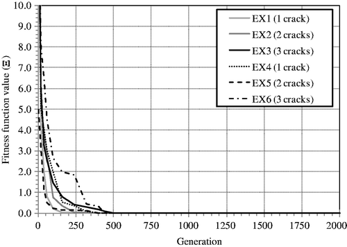
Figure illustrates the evolutionary process of fitness function converged to the best fitness values in Table . Most of numerical examples converge after 500 generations. Figures show the distribution of stiffness reduction obtained from the estimated variable with respect to bivariate Gaussian distribution function. The centre of the estimated bivariate Gaussian distribution function is located on the geometrical centre of single or multiple cracks. In figures, the bold lines show the position of cracks at a 3-D bridge deck model. In Figures and , the estimated -coordinates (
) of the centre of maximum stiffness reduction element for EX1 and EX4 are 2.17 and 3.02, respectively. From these values, errors of approximately 8.50% and 0.73% are obtained compared with the position of cracks at a 3-D model, which may be more or less inaccurate results but the overall shape in the distribution of the stiffness reduction is exhibited reasonably. For EX2, EX3, EX5 and EX6 with multiple cracks, the individual locations about each crack are not obtained from the estimated
and
. The estimated values mean the geometrical centre of single or multiple cracks because a single modified bivariate Gaussian function is used to exhibit an overall stiffness reduction distribution. It can be observed from Figures ,, and 11 that the stiffness reduction property induced by the prescribed localized multiple cracks are relatively accurately transformed to overall stiffness reduction distributions of equivalent plate elements, as expected.
Figure 6. Estimated distribution of stiffness reduction for EX1. (a) 3-D view of stiffness degraded distribution. (b) Plane view of localized damage induced by a single crack.
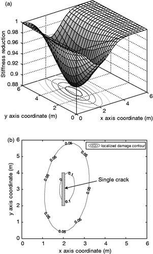
Figure 7. Estimated distribution of stiffness reduction for EX2. (a) 3-D view of stiffness degraded distribution. (b) Plane view of localized damage induced by multiple cracks.
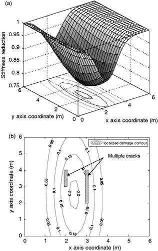
Figure 8. Estimated distribution of stiffness reduction for EX3. (a) 3-D view of stiffness degraded distribution. (b) Plane view of localized damage induced by multiple cracks.
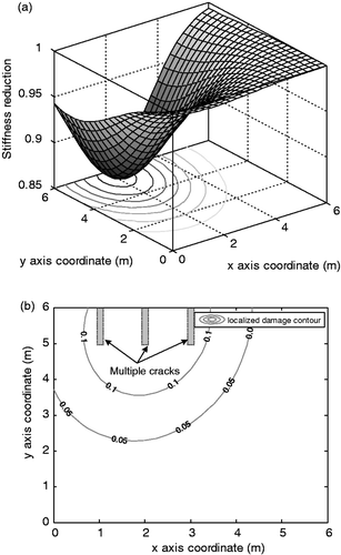
Figure 9. Estimated distribution of stiffness reduction for EX4. (a) 3-D view of stiffness degraded distribution. (b) Plane view of localized damage induced by a single crack.
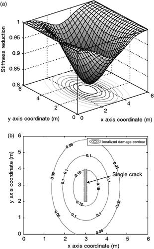
Figure 10. Estimated distribution of stiffness reduction for EX5. (a) 3-D view of stiffness degraded distribution. (b) Plane view of localized damage induced by multiple cracks.
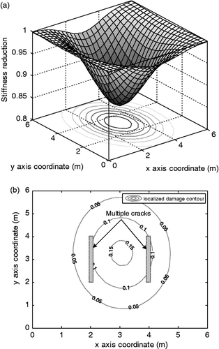
Figure 11. Estimated distribution of stiffness reduction for EX6. (a) 3-D view of stiffness degraded distribution. (b) Plane view of localized damage induced by multiple cracks.
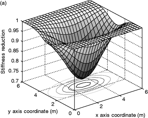
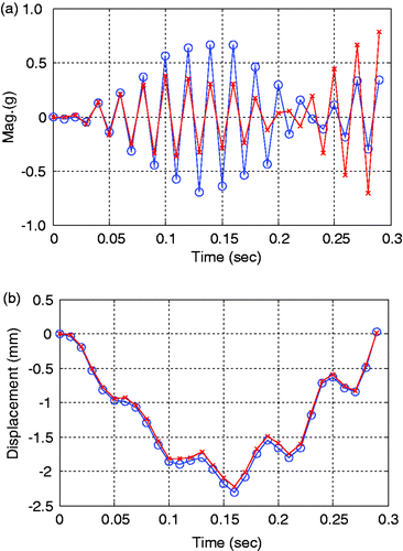
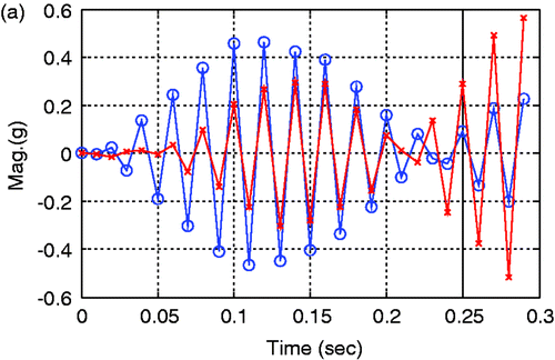
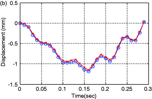
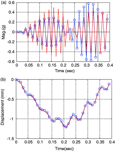
Dynamic responses measured at the center of a 3-D model and 2-D equivalent plate model for a concrete slab are shown in Figures . Here, the measured response means that it is actually obtained from the analytical model by calculation. For dynamic displacements, the behaviours of the two models are very similar but, for dynamic accelerations, the relatively large difference of them is shown locally. Among the response data such as displacements, velocities, and accelerations, detection technologies based on accelerations is more practical than them based on the others in the real field because acceleration data can be directly obtained from normal accelerometers. For these reason, in this study, acceleration-based detection was performed. Although there is a modelling error between the two models as shown in the figures, the proposed technique can overcome model uncertainty by applying the h-GA, basically stochastic algorithm and, consequently, the characteristics of moving loads and damages can be relatively exactly estimated simultaneously.
Figure 12. Dynamic response data obtained at the center in a slab for EX1 (-x-: 2-D equivalent plate model; -o-: 3D-reality solid model). (a) Acceleration. (b) Dynamic displacement.
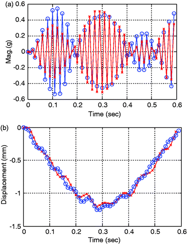
Figure 13. Dynamic response data obtained at the center in a slab for EX2. (-x-: 2-D equivalent plate model; -o-: 3D-reality solid model). (a) Acceleration. (b) Dynamic displacement.
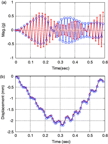
Figure 14. Dynamic response data obtained at the center in a slab for EX3. (-x-: 2-D equivalent plate model; -o-: 3D-reality solid model). (a) Acceleration. (b) Dynamic displacement.
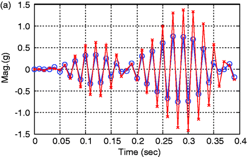
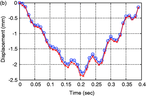
Figure 15. Dynamic response data obtained at the center in a slab for EX4. (-x-: 2-D equivalent plate model; -o-: 3D-reality solid model). (a) Acceleration. (b) Dynamic displacement.
4.3. Noise effects
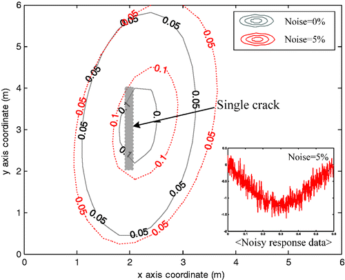
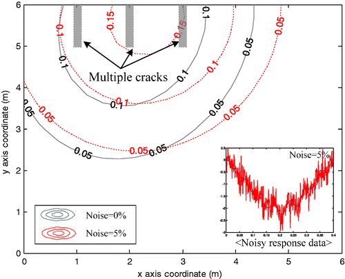
We consider the effect of unexpected noise when introduced into the measurement data. The noise effect is investigated by adding Gaussian noise of different levels directly into the input data obtained from the forward procedure Citation17. With this setup, we make an attempt to detect the location, extent, and distribution of the damage by determining the six unknown parameters. Figures and show the stiffness degradation obtained by the computation at 5% noise for EX1 and EX3. The local difference between the results obtained at 0% and 5% noise level is observed from the figures. However, the difference for the overall stiffness distribution is found to be relatively small regardless of different damage types. Under the consideration of unexpected errors in the measurement, the proposed method is also useful for detecting the damage.
5. Summary and conclusions
In this study, the characteristics of damages and moving loads in a concrete slab bridge subjected to unknown moving loads are estimated by using the h-GA, which has a superior computational efficiency. In order to consider a modelling error, in this study, dynamic responses obtained from a 3-D model under a moving load are used as a measurement data. Parametric case studies showed that the proposed technique combined the FEM and the h-GA is adequate to detect the properties of damages and moving loads. Based on present computational results, the following conclusions may be derived.
| 1. | The characteristics of moving loads such as velocities and weights are exactly estimated with small error for all examples (EX1, EX2, EX3, EX4, EX5 and EX6) considered in this study. | ||||
| 2. | The stiffness reduction property induced by the prescribed localized single or multi cracks are relatively accurately transformed to overall stiffness reduction distributions of equivalent plate elements by using the modified bivariate Gaussian distribution function. | ||||
| 3. | Although there is a modelling error between the 3-D model and the 2-D equivalent plate model, the proposed technique can overcome model uncertainty by applying the hGA, basically stochastic algorithm; consequently, the characteristics of moving loads and damages can be relatively exactly estimated simultaneously. | ||||
| 4. | Regarding the occurrence of unexpected errors in the measurement, it is found that the estimated error increases at 5% noise level. However, the difference between the results obtained at the different damage types is negligible. | ||||
It is concluded from numerical examples that the proposed method works well for the numerical experiments that were tested. However, the used single or multi damage case examples presented here need to be extended to more realistic situations having irregularly distributed cracks or damages. It is therefore necessary that the proposed technique should be modified to estimate stiffness condition of a bridge with multiple damages by using several bivariate Gaussian functions. In addition, in order to more accurately estimate the damage behaviour of a bridge, advanced study that can estimate stiffness reduction from damage or crack models is needed.
References
- Law, SS, Chan, THT, and Zeng, QH, 1997. Moving force identification: A time domain method, J. Sound Vib. 201 (1) (1997), pp. 1–22.
- Law, SS, Chan, THT, and Zeng, QH, 1999. Moving force identification: A frequency and time domain analysis, J. Dyn. Syst. Meas. Contr., ASME 121 (3) (1999), pp. 394–401.
- Chan, THT, Law, SS, Yung, TH, and Yuan, XR, 1999. An iterative method for moving force identification, J. Sound Vib. 219 (3) (1999), pp. 503–524.
- Steffen, V, and Rade, DA, 1991. An identification method of multi-degree-of-freedom systems based on Fourier series, Int. J. Anal. Exp. Modal Anal. 6 (4) (1991), pp. 271–278.
- Chan, THT, Law, SS, and Yung, TH, 2000. Moving force identification using an existing prestressed concrete bridge, Eng. Struct. 22 (10) (2000), pp. 1261–1270.
- Chan, THT, and Ashebo, DB, 2006a. Theoretical study of moving force identification on continuous bridge, J. Sound Vib. 295 (3) (2006a), pp. 870–883.
- Chan, THT, and Ashebo, DB, 2006b. Moving axle load from multi-span continuous bridge: Laborlatory study, J. Vibr. Acoust., ASME 128 (4) (2006b), pp. 52–526.
- Marwala, T, 2000. Damage identification using committee of neural networks, J. Eng. Mech., ASCE 126 (1) (2000), pp. 43–50.
- Suh, MW, Shim, MB, and Kim, MY, 2000. Crack identification using hybrid neuro-genetic technique, J. Sound Vib. 238 (4) (2000), pp. 617–635.
- Mares, C, and Surace, C, 1996. An application of genetic algorithms to identify damage in elastic structures, J. Sound Vib. 195 (2) (1996), pp. 195–215.
- Friswell, MI, Penny, JET, and Garvey, SD, , A combined genetic and eigensensitivity algorithm for the location of damage in structures, Comput. Struct. 69 (1998), 547–556.
- Chou, JH, and Ghaboussi, J, 2001. Genetic algorithms in structural damage detection, Comput. Struct. 79 (14) (2001), pp. 1335–1353.
- Krawczuk, M, 2002. Application of spectral beam finite element with a crack and iterative search technique for damage detection, Finite Elem. Anal. Des. 38 (6) (2002), pp. 537–548.
- Abu-Lebedh, G, and Benekothal, RF, 1999. Convergence variability and population sizing in micro-genetic algorithms, Comput-Aided Civil Infrastruc. Eng. 14 (5) (1999), pp. 321–334.
- Carroll, DL, 1996. Chemical laser modeling with genetic algorithms, Am. Inst. Aeronaut. Astronaut. J. 34 (2) (1996), pp. 338–346.
- Au, FTK, Cheng, YS, Tham, LG, and Bai, ZZ, 2003. Structural damage detection based on a micro-genetic algorithm using incomplete and noisy modal test data, J. Sound Vib. 259 (5) (2003), pp. 1081–1094.
- Lee, SY, and Wooh, SC, 2005. Waveform-based identification of structural damage using the combined fem and microgenetic algorithms, J. Struct. Eng., ASCE 131 (9) (2005), pp. 1464–1472.
- Rus, G, Lee, SY, Chang, SY, and Wooh, SC, 2006. Optimized damage detection of steel plates from noisy impact test, Int. J. Numer. Methods Eng. 68 (7) (2006), pp. 707–727.
- Rus, G, Lee, SY, and Gallego, R, 2005. Defect identification in laminated composite structures by BEM from incomplete static data, Int. J. Solids Struct. 42 (5–6) (2005), pp. 1743–1758.
- Lee, SY, Park, T, and Voyiadjis, GZ, 2008. Detection of stiffness reductions in concrete decks with arbitrary damage shapes using incomplete dynamic measurements, J. Eng. Mech., ASCE 134 (7) (2008), pp. 567–577.
- Park, T, Noh, M-H, Lee, S-Y, and Voyiadjis, GZ, 2009. Identification of a distribution of stiffness reduction in reinforced concrete slab bridges subjected to moving loads, J. Bridge Eng., ASCE 14 (5) (2009), pp. 355–365.
- Gudmudson, P, 1983. The dynamic behaviors of slender structures with cross section cracks, J. Mech. Phys. Solids 31 (4) (1983), pp. 329–345.
- Christides, S, and Barr, ADS, 1984. One-dimensional theory of cracked Bernulli-Euler beams, Int. J. Mech. Sci. 26 (11/12) (1984), pp. 639–648.
- ABAQUS, Defining homogeneous solid elements, Online manual, Version 6.5. (2008), Available at http://2080/v6.5/books/usb/default.htm.
- ABAQUS, Amplitude curves, Online manual, Version 6.5. (2008), Available at http://v6.5/books/usb/default.htm/startat/pt06ch19s01aus87.html/usb-prc-pamplitude.
- Azizinamini, A, Boothby, TE, Shekar, Y, and Barnhill, G, 1994. Old concrete slab bridges I: Experimental investigation, J. Struct. Eng., ASCE 120 (1) (1994), pp. 3284–3304.
