 ?Mathematical formulae have been encoded as MathML and are displayed in this HTML version using MathJax in order to improve their display. Uncheck the box to turn MathJax off. This feature requires Javascript. Click on a formula to zoom.
Abstract
This article deals with ultrasonic transmission through multilayer systems. The equivalent ultrasonic impedance of such systems is based on the transmission line built as a convenient model to reduce the computational time for numerical evaluation. Also, the one dimensional wave equation is considered as the full model for the propagation of a plane wave inside the material. From numerical simulations, we obtained signals useful to assess the equivalent model. Results clearly depict coherence between the models since there are full agreements in the computed velocity and stress at each interface.The identification of the parameters involved in the model, characteristic acoustic impedance and time of flight, related to the layer densities and propagation velocities, is posed as a non-linear parameter estimation problem. An ultrasonic transmission is set up and the complete waveform is recorded after travelling through the layers. The minimization of a least squares objective function defined to measure the misfit between the real and predicted waveforms, in frequency, was successfully performed and the estimated parameters give useful information for the mechanical characterization of the sample.
1. Introduction
The interest of an accurate identification of multilayer materials properties is constantly growing, since they are encountered in various engineering applications, in material science developments and in biomedical research in human tissues. Some layered materials are the products of synthetic chemistry and represent a large class of compounds formed by metals, ceramics, polymers or fibre-reinforced polymers. Methods for non-destructive inspection of layered materials based on ultrasonic tests are becoming more and more popular for a wide range of industrial applications as a way of assuring product integrity and quality, and also as a mean to achieve its mechanical characterization [1–3]Citation1Citation2Citation3. Ultrasonic waves are high-frequency (20 kHz–100 MHz) mechanical waves adequate to monitor in situ materials with diverse geometries, allowing their characterization when other tests are not realizable. The ultrasonic evaluation is also applicable in the inspection of biological tissues, as in the monitoring of the adhesion of implants in bones Citation[4].
Because of the intricate nature of ultrasonic waves, theoretical and numerical aspects of the physical problem have been studied in last few decades to model and explain the behaviour of ultrasonic non-invasive phenomena [5,6]Citation5Citation6. The derived models have been established to examine the generation, propagation and interaction of elastic waves in solid materials for non-destructive evaluation and because of the need to find solutions to the inverse characterization problem. Finite element models (FEM) are robust techniques to predict and visualize ultrasonic propagation in complex structures. The limitation in this tool is the computational time required to process the code, which is related to the mesh refinement necessary to obtain accurate solutions. Under certain assumptions, tests for the characterization of layered materials, the matter of this article, can be well represented by means of equivalent models based on electric circuits [5–7]Citation5Citation6Citation7.
The goal of this paper is to detail the method to identify acoustic properties of layered materials from a transmission ultrasonic experiment using the stress waveform measured at the end of the sample. We present a novel model-based technique to process the data, using transmission lines (T-line). Previous articles [8,9]Citation8Citation9 have reported that T-lines can be used to represent the propagation of plane longitudinal waves (L-waves) in a generally isotropic medium. Additionally, in Castillo et al. Citation[8] and Maione et al. Citation[10], T-lines are used to model lossy transducers using a one-dimensional scheme based on Mason’s model Citation[11]. The ultrasonic model implemented in this manner allows the determination of acoustical stress at any interface within the material. From an electro-acoustical analogy, these stresses correspond to the voltages calculated along the T-line cascade. Circuit simulation programmes are suitable and very efficient to assess the equivalence between the models; thus, we carried out the simulation of the forward problem by means of LTspice software.Footnote1 Nevertheless, a computer program for the numerical calculation should be developed to implement the methodology to solve the inverse problem. Since the solution of the forward problem is essential for the later solution of the inverse problem, we dedicate the following two sections to the description and simulation of the direct problem.
Section 4 presents the formulation and analysis of the inverse problem. For the proposed procedure, an ultrasonic transmission is simulated and the complete waveform is recorded after travelling through the set of layers. The problem is posed as an inverse problem, in which the unknown is a reduced set of parameters that describes the sequence of layers. The values of the parameters that best describe the material are obtained by minimizing the misfit between the true and the numerically predicted stresses expressed in the frequency domain. This is done by defining a scalar cost functional and minimizing it for the parameters. Finally, Section 5 describes the results obtained applying the proposed methodology for several three-layered samples, and last section summarizes the conclusions of the work.
2 Model description
The displacement of the material particles of an isotropic elastic solid, in which an ultrasonic plane wave is propagating in the x-direction at time t, is denoted as a function u(x,t). The well-known wave equation describes the displacement dynamics, which in a medium having constant propagation velocity, c, is expressed as:(1)
(1)
The case of a layered material formed by homogeneous layers can be considered as a piecewise medium, where Equation (1) holds in each layer for a different value of the propagation velocity. Additionally, continuity conditions for particles stress and velocity
must be fulfilled at the interfaces. In this work, we consider an equivalent circuit as an alternative representation of the same problem.
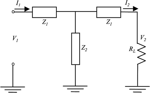
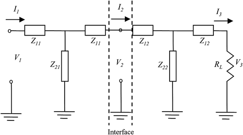
An equivalent circuit is a one-dimensional model that describes the analogue electrical characteristics of an acoustic structure. The task to develop such a model has been done for piezoelectric and non-piezoelectric materials [5,6]Citation5Citation6. The voltage and current in the equivalent system stand for stress and velocity of the material particles, respectively. The circuit in Figure is a valid description of a non-piezoelectric medium. It is a lumped element representation of an acoustic transmission, or delay line. For a two-layer medium, considered as generally isotropic, i.e. all the individual layers are independently isotropic, the equivalent circuit is that shown in Figure . It can be derived [6,7]Citation6Citation7 that the involved impedances are(2)
(2)
where, Z1, Z2, τ1, τ2 are impedances and delays of the electric circuit. Voltage (V2) and current (I2) at the interface are related to the input and output voltages and currents by relations (3) and (4).(3)
(3)
(4)
(4)
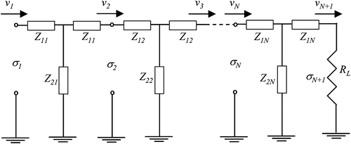
For a multilayer material, the model is made up of as many transmission lines connected in series as layers as present in the sample. Thus, for an N-layered medium, considered as generally isotropic, the equivalent circuit is that shown in Figure . Using the electrical–acoustical analogy, we consider that the signals actuating in the circuit are the stress and velocity of the material particles and that the parameters involved are the characteristic acoustic impedance and the ultrasonic pulse time of flight corresponding to the material of each layer, expressed as:(5)
(5)
where, ρi, ci and di are specific mass, propagation velocity and thickness of layer i, respectively. The transference of stress and velocity between both ends of the specimen is obtained, similarly to Equations (3) and (4), multiplying the corresponding N matrices:(6)
(6)
It is worth noticing that relations (3), (4) and (6) are derived strictly from the full model Citation[5,Citation6], and that they give a closed form of the signals in the frequency domain at the interfaces of the specimen, considering that σ1 is the excitation signal applied to one end of the sample.
3 Simulations and results for the forward problem
The solution of the forward ultrasonic transmission problem (Equation (1)) gives, in principle, the displacement field of the material particles u(x,t) at any time and position. Also, from the displacement, the particles stress field σ(x,t) is obtained in a straightforward way. Using the equivalent model just introduced, particles velocity and stress can be known only at the interfaces, where we expect them to coincide with those obtained from the full model. It is worthwhile to compare the computational effort required to obtain the numerical solutions for both models. We have used available simulation tools as well as computer programs specifically developed. For the numerical solution of Equation (1) using FEM, COMSOL Multiphysics® softwareFootnote2 is suitable; on the other hand, the environment provided by LTspice efficiently simulates T-lines.
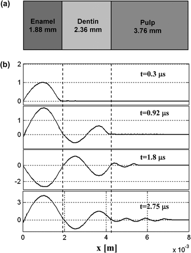
Among different physical problems where multilayer material properties are the matter of study, we consider first, as an example, one related to the detection and characterization of features in human tissue [4,9]Citation4Citation9. The particular case of a three-layers specimen representing part of a tooth structure (Figure ) is referred as Material 1 in Table , where the physical parameters’ true values are transcribed Citation[9].
Table 1. Physical and acoustical parameters of analyzed samples.
Curves shown in Figure depict stress profiles, σ(x,t), due to the ultrasonic wave travelling through the layers within the material at four different times. The curves are obtained by COMSOL® using the following conditions: continuity of stress and velocity at each interface and sound-hard boundary at the material faces perpendicular to the interfaces, in order to assure the validity of the plane wave propagation assumption. The stress in the material is a consequence of a radio frequency pulse (Figure ) applied as a boundary condition for the stress at one end of the sample, i.e. for x = 0, while at the other end, an impedance condition is considered, represented by RL in the equivalent circuit of Figure . For the transmission test, we are assuming that the sample is initially at rest, so all initial conditions are zero.
Figure 5 Stress waveforms at: (a) enamel face; (b) enamel/dentin interface; (c) dentin/pulp interface; (d) pulp end. (Grey line: FEM. Black line: equivalent model.)
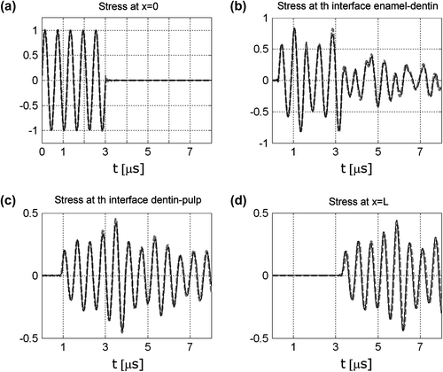
The temporal stress waveforms at the interfaces of the same tooth structure obtained by COMSOL® are the signals plotted in dashed lines in Figure , which are almost coincident to those obtained by the equivalent model (solid lines), as expected. These curves represent the solution calculated by the computer programs specifically developed to implement the hybrid methodology consisting of the following steps:
The analytic computation of
, according to (6).
The numerical computation of the temporal stress waveform,
, accomplished approximating the direct calculation of the inverse Fourier transform in terms of the real and imaginary components of the Fourier Transform as:
Notice that it is necessary to compute to fulfil step 1. Defining as Zin, the input equivalent impedance of the T-Line and using Ohm’s law to relate the analogue quantities, the calculation of
is done as:
(8)
(8)
The best approximation in Equation (7) is obtained, asymptotically, as W1 and Δω values are set close to zero, and W2 value is chosen to be as large as possible. Particularly, for the case shown in Figure , setting Δω = 2 × 10⁴ rad s−1, W1 = 0.001 rad s−1, W2 = 2 × 10⁷ rad s−1, differences can be neglected as can be observed in Figure , with relative mean square errors of 1.6, 2.3 and 4.8%, respectively.
The verification that the equivalent model, simulated using MATLAB®, provides predictions similar to the full model, is as important as the fact that the gain in the computational time is very high. For the example considered, we found that to calculate the stress waveforms plotted in Figure , the processing time is 30 times less than the time required by FEM using COMSOL®. The efficiency in the numerical computation of the forward problem is essential since the inverse problem requires the repeated solution of the direct problem.
4 Inverse problem analysis
We approach the identification of the acoustical parameters of the layers of a compound material formulating an inverse problem. For this problem, the data available come from the stress signal in the frequency domain, , registered at the end of the sample, since we are considering a transmission test. In this article, the measurement,
, is simulated adding noise, ϵ(t), to the temporal stress waveform at the material end,
,
(9)
(9)
where is obtained solving theoretically the problem defined in Equation (7) for the true values of the unknown parameters, pt and ϵ(t) is represented by a white-gaussian random process. The Fourier transform of the simulated measurement
is numerically computed using the well-known fast Fourier transform algorithm Citation[12].
A minimization problem formulated by a least squares functional (Equation (10)) is to be solved to obtain the parameter vector, p, i.e.:(10)
(10)
where is the stress obtained from the equivalent model (Equation (6)), for a given p. The searched parameter vector p contains the ultrasonic pulse time of flight, τ, and the characteristic acoustic impedance, Z, of each layer. For the numerical solution of the problem, we consider an alternative cost functional based on the real components of the complex quantities present in Equation (10):
(11)
(11)
for discrete measurements registered at M different frequencies.
To evaluate , the computation of
for each p, and also, the velocity
as in Equation (8) are required. The non-linear relation between the unknown parameters and
is evident from Equation (6). Since in general, it is not possible to assess uniqueness and existence of the solution of the least squares problem defined by the cost functional of Equation (11) for cases where the formulation of the forward problem is non-linear, we analyzed the problem features considering particular cases. In this article, we focus on different compound materials formed by three layers, so we expect to obtain an estimation of
as the solution of the inverse problem. We also consider two different cases regarding the excitation signal applied,
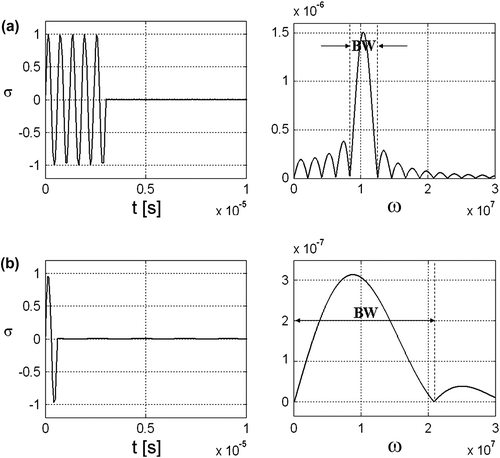
, which temporal and frequency representations are illustrated in Figure . Case 1 corresponds to a signal with a narrow frequency bandwidth, and case 2, to one with a broad bandwidth.
Figure 6 Temporal representation and amplitude spectra of the excitation signals: (a) narrow bandwidth signal; (b) broad bandwidth signal.
The formulated problem can in principle be minimized implementing a numerical optimization methodology, such as the well-known Levenberg–Marquardt Citation[13]. The updating process for the estimation of parameter p is carried out doing(12)
(12)
where δk is computed solving:(13)
(13)
is the Jacobian matrix of F and λk is a scalar which controls the magnitude and direction of δk in order to ensure convergence, determined internally in the algorithm at each iteration. In our problem, according to Equation (11):
(14)
(14)
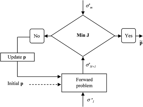
The iterative procedure of Equation (13) is schematically depicted in the flow diagram of Figure . The parameters’ initial values, chosen following the methodology explained below, are used only to start the process which continues until the change in J is less than the tolerance level. The solution of the inverse problem is given by the values obtained for the parameters in vector .
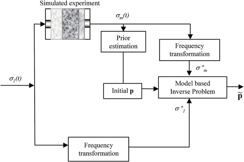
The complete diagram in Figure shows the necessary data pre-processing in order to succeed in finding the global minimum. In this figure, the block labelled as ‘Frequency transformation’ indicates the calculation of the Fourier transform and the selection of the frequency band window (BW) used to evaluate the stress signals at both ends of the material. The methodology to choose the parameter initial values, indicated in the ‘Prior estimation’ block, is based on the echoes of the transmitted registered signal.
4.1 Selection of the frequency BW
Properties of the inverse problem can be analyzed from features of the cost functional, J(p). In this problem, we have observed that some of them are related to the frequency range used to compute Equation (11). For instance, in Figure , we show the surface obtained when J(p) is plotted against τ1 and τ2, fixing all other parameters at their true values, for the sample named in this work as Material 1 (Table ). This surface is not independent of the frequency range involved in the evaluation of J(p). Figure is obtained for a frequency BW centred at the maximum of the power spectrum, as indicated in Figure . The smoother surface shown in Figure was found using in Equation (11) a frequency range [ω1:ωM] defined for lower frequencies.
Although the global minimum is perfectly defined for the same values of the parameters in both surfaces, the evolution of the algorithm will not be the same. We note three aspects which lead us to the choice of the frequency BW. Fewer local minima are observed in Figure than those in Figure ; apparently, it would be more likely to achieve the global minimum as the problem solution in the situation described in Figure . Besides, other two issues arise: the smoother surface shown in Figure that implies slow convergence and worst efficient algorithm performance and the small signal to noise relation present that will degrade the precision of the parameter estimations.
Because of the disadvantages stated, working with the BW centred at the maximum of the frequency spectra is recommended. The problem related to the fact that the surface bears multiple minima can be tackled selecting the initial values of the times of flight not far from the true values.
4.2 Selection of the parameter initial values
The selection of proper initial values for a non-linear optimization procedure is often crucial to find the global minimum. In the particular problem in hand, we have detected that the complete uncertainty of the characteristic impedances values does not imply an increase in the difficulty of solving the inverse problem; actually, from random initial values, the right solution is found. Contrarily, the times of flight must be initialized properly. They appear in the argument of trigonometric functions in the forward problem of Equation (6) and these cyclic non-linear relations produce many local minima in functional of Equation (11), as addressed above.
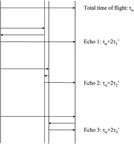
Based on the single transmission waveform measured, we were able to obtain good prior estimations of the times of flight detecting the echoes corresponding to the different layers. This is possible for different kinds of layered materials with combinations of thickness and propagation velocities such that the arrival times are related to the times of flight by simple relations (Figure ). Thus, measuring the total time of flight, τα = τ1′ + τ2' + τ3′, the arrival time for the first echo, τα + 2τ1′ and for the second one, τα + 2τ′2, prior estimations of the times of flight (τ1′, τ2′, τ3′) can be obtained. Actually, these values cannot be assigned to a particular layer, but they can be used as trial initial values as far as no echoes overlapping occur. Whether the assumed order for the obtained times of flight, τ1′, τ2' and τ3', is different from the true one, the optimization procedure will most likely fail in finding the global minimum, but it will succeed only for the right order.
In the cases considered in this article, this methodology was tested trying all possible order combinations and actually, only for the right order, the optimization was successfully performed and the global minimum was reached. In addition, the implementation of a pulse echo set-up scheme as in Citation[14] could be applied.
5 Results
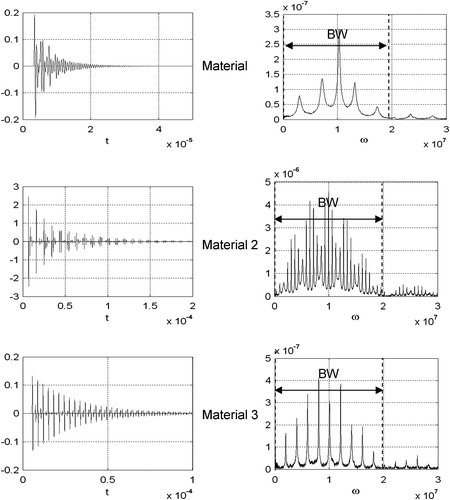
The proposed methodology was tested on simulated examples for three-composed layered materials with true properties transcribed in Table . As addressed in last section, we considered two different cases regarding the excitation pulse applied; case 1 refers to a stress waveform, depicted in Figure , with a narrow frequency bandwidth, and case 2 corresponds to the broad frequency bandwidth signal of Figure . RL is assumed to be 1.5 MRayls for Materials 1 and 3, and 50 MRayls for Material 2. The measurements were simulated solving the forward problem, based on Equations (6)–(8) and perturbed by noise of different levels to consider more realistic situations (Equation (9)). Figure shows, for each case, the temporal and frequency representation of the stress waveform transmitted to the end of the different samples. These curves were obtained adding a single realization of zero-mean non-correlated noise with standard deviation stdϵ = 1% related to the maximum value of the temporal stress. The frequency BW selected to be used in the optimization procedure is highlighted on the plots.
Figure 11(a) Temporal representation and amplitude spectra of simulated stress measurements in case 1.
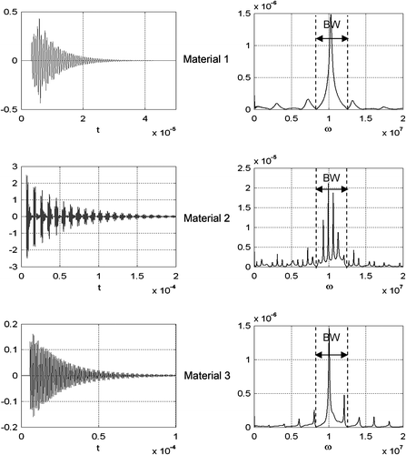
Figure 11(b) Temporal representation and amplitude spectra of simulated stress measurements in case 2.
The selection of the parameter initial values required to start the optimization procedure was properly accomplished using each transmitted waveform stress. The plots, at higher resolution in Figure , show that the echoes can be detected and quite good prior estimations of the times of flight of the layers were calculated for the six cases considered in this article. It should be emphasized that the shorter the excitation pulse is, the easier the identification of the echoes will be. Thus, the estimations obtained using cases 2 were more accurate. From these values, transcribed in Table , and several sets of initial values for the characteristic impedances Z1, Z2, Z3 randomly selected, the minimization of the cost functional in Equation (11) was successfully performed. The final estimated values for the layers’ parameters corresponding to the three analyzed materials are shown in the last two columns of Table .
Figure 12 Measured temporal stress [Pa] at higher resolution. (Grey line: case 1. Black line: case 2.)
![Figure 12 Measured temporal stress [Pa] at higher resolution. (Grey line: case 1. Black line: case 2.)](/cms/asset/96cea63a-3180-4aab-884b-9e2b9d620e0e/gipe_a_757312_f0012_b.gif)
Table 2. Estimated parameter values. (Noisy measurements (stdϵ = 1%).)
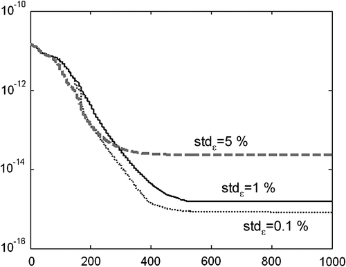
Although often inverse problems are unstable due to their ill-condition nature, the problem in hand was stable. In fact, as the noise level increases, the error in the estimations increases but it remains in the range of the measurement error. The stability analysis was performed observing the evolution of the cost functional for different initial values of the characteristic impedances and different noise levels. Particularly, in Figure , this evolution is shown for Material 2 using three levels of noise and an arbitrary initial values given by Z1 = Z2 = Z3 = 5 MRayls. As expected, the cost functional converges to a value that is in concordance to the noise level.
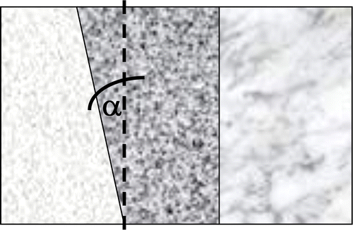
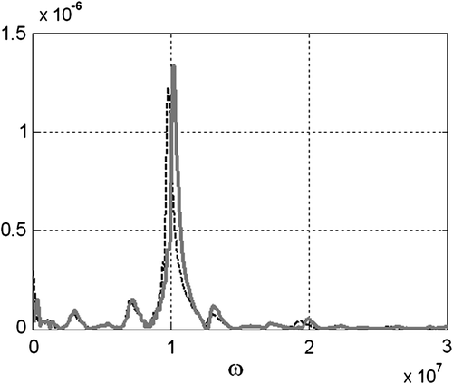
As addressed before, T-line models represent exactly a one-dimensional problem, adequate to represent materials with perfectly parallel interfaces. When this requirement is not fulfilled, the application of the equivalent model to predict the waveform in the inverse problem introduces modelling errors. We carried out the study of some particular samples where the interfaces are plane but not parallel, in which wave diffraction effect will be present; then, the true stress waveform can be rigorously computed using FEM. Three cases have been studied considering a perturbed geometry obtained modifying the angle α of one of the interface planes as shown schematically in Figure (A: α = 1.14° and B: α = 2.52° at interface 1; C: α = 1.14° at interface 2). This situation was considered for samples composed by layers like those of Material 1 and where the excitation pulse used for transmission test was that of case 1. Since the application of the equivalent model will introduce modelling errors, the simulated stress will be different from that obtained using FEM. The amplitude spectra of both transmission waveforms simulated by FEM and by the equivalent model are shown in Figure .
Figure 15 Amplitude spectra of simulated stress measurements. Material sample with non-parallel interfaces. FEM (black, dash line); equivalent model (grey, full line).
The inverse problem was solved based on the equivalent model, and the same iterative procedure described in Section 4 was followed. The obtained estimations for the layers parameter are shown in Table . Although the errors have increased, the values obtained are good approximations and give useful information about the layer characteristic acoustic impedances. The robust performance of the methodology for modelling errors can be assessed for the analyzed cases.
Table 3. Estimated parameter values. Modelling errors are considered.
6 Conclusions
In this work, we have successfully assessed the usage of electric equivalent circuits to obtain the stress waveforms that appear at the interfaces of a layered material under a transmission ultrasonic simulated experiment. The forward problem that takes a closed form in the frequency domain, and a numerical approximation of the inverse Fourier transform were implemented to obtain the stress waveforms. The waveforms simulated using the equivalent model have the same level of accuracy as those obtained by FEM with a significant saving of computational time, crucial in applications which demand fast decisions based on model predictions.
We investigated the feasibility of identifying multilayer material acoustical properties formulating an inverse problem for the ultrasonic transmission experiment. The proposed procedure is based on the recording of the complete waveform after travelling through the set of layers. The problem is posed as an inverse problem, in which the unknown is a reduced set of parameters related to the ultrasonic properties of the sequence of layers. The model that depends on the parameters is used to predict the transformation of the waveform and compare to the measurement. A scalar cost functional was defined to quantify the misfit between the data, a synthetic waveform in this work, and the numerically predicted waveforms based on the equivalent model.
Issues like the existence of a unique solution and the stability of the numerical solution were analyzed. Also, the connection between the frequency range used to evaluate the functional and the existence of multiple minima, the convergence time and the signal to noise relation was studied. As a result, a proper frequency BW for solving the inverse problem could be selected and the optimization algorithm succeeded in finding the global minima provided that the initial values of the times of flight were close to the true ones. Particularly, the values of the characteristic impedances and the times of flight of several three-layered composed materials were precisely calculated, although the times of flight required a previous estimation based on the observation of the transmitted stress waveform. The stability of the solution is supported by the results obtained from many simulated experiments developed using noisy data, in which the algorithm converged without the necessity of adding any regularization term.
The methodology was also applied to some cases where the hypotheses for the equivalent model do not hold. In all the analyzed samples, the six parameters were well estimated, verifying the robust condition of the proposed strategy for measurement and modelling errors.
Acknowledgements
The authors acknowledge the financial support from CONICET, Universidad Nacional de Mar del Plata (Argentina) and Universidad de Santiago de Chile (Chile).
Notes
1. LTspice IV made by Linear Technology. Available free from Linear Technology at: http://www.linear.com/company/software.jsp.
2. COMSOL Multiphysics® Multiphysics is a registered trademark of COMSOL AB.
References
- HägglundF, CarlsonJE, AndersonT. Ultrasonic classification of thin layers within multi-layered materials. Meas. Sci. Technol. 015701. 2010;21:9.
- BochudN, GomezA, RusG, CarmonaJL, PeinadoA. Robust parameterization for non-destructive evaluation of composites using ultrasonic signals. ICASSP-IEEE, Praga. 2011; 1789–1792.
- FellahZEA, MitriFG, FellahM, OgunE, DepollierC. Ultrasonic characterization of porous absorbing materials: Inverse problem. J. Sound Vib. 2007;302:746–759.
- RusG, García-MartínezJ. Ultrasonic tissue characterization for monitoring nanostructured TiO2-induced bone growth. Phys. Med. Biol. 2007;52:3531–3547.
- KinoG. Acoustic Waves: Devices, Imaging and Analogue Signal Processing. Englewood Cliffs, NJ: Prentice-Hall; 1987.
- RosenbaumJ. Bulk Acoustic Waves Theory and Devices. Norwood, MA: Artech House; 1988.
- CheekeJDN. Non-Destructive Evaluation (NDE) of Materials in Fundamentals and Applications of Ultrasonic Waves. Boca Raton, FL: CRC Press LLC; 2002.
- CastilloM, AcevedoP, MorenoE. KLM model for lossy piezoelectric transducers. Ultrasonics. 2003;41:671–679.
- GhorayebSR, MaioneE, La MagnaV. Modelling of ultrasonic wave propagation in teeth using Pspice: a comparison with finite element model. IEEE Trans. UFFC. 2001;48:1124–1131.
- MaioneE, TortoliP, LypacewiczG, NowickiA, ResidJM. Pspice modelling of ultrasonic transducers: comparison of software models to experiment. IEEE Trans. UFFC. 1999;46:399–406.
- Mason WP. Electromechanical Transducer and Wave Filters: 2nd ed. New York: D. Van Nostrand; 1948.
- OppenheimAV, SchaferRW. Digital Signal Processing. Englewood Cliffs, NJ: Prentice Hall; 1975.
- MarquardtD. An algorithm for least-squares estimation of nonlinear parameters. SIAM J. Appl. Math. 1963;11:431–441.
- Gómez JC, Gwirc S. Medición de espesores delgados con ultrasonido [Thin thickness measurement with ultrasonics], Universidad de La Matanza, Buenos Aires, Argentina, Congreso de Microelectrónica Aplicada, 2010, pp: 225–228.
![Figure 9 J(p) vs. p=[τ1τ2]T, (a) 8.35.106 < ω < 12.53 × 10⁶; (b) 0 < ω < 5 × 10⁶ (ω [rad s−1]).](/cms/asset/2169fc75-7465-4498-a1d6-e617b212d6da/gipe_a_757312_f0009_oc.gif)
