 ?Mathematical formulae have been encoded as MathML and are displayed in this HTML version using MathJax in order to improve their display. Uncheck the box to turn MathJax off. This feature requires Javascript. Click on a formula to zoom.
Abstract
Micromanipulation is an active research topic in the development of MEMS devices. At the microscale the microforces encountered are highly nonlinear and behave differently than their macroscale equivalent ones. Thus, if an inverse problem were to be posed in the MEMS world, the problem could be investigated and the parameters identified using non-traditional evolutionary based approaches. In this manuscript, the notion of a microconveyor platform along with the highly nonlinear microscale forces of the interaction between the microconveyor and a micropart is introduced. The proposed microconveyor platform for micromanipulation based on the active surface concept is investigated for the controlled translocation of a micropart to a predefined destination in minimum time and within a predefined distance tolerance. The current work poses the microconveyor concept as an inverse problem that aims to identify the optimum values of system control parameters for controlled micropart motion. Differential evolution is employed for solving this inverse problem because of the discontinuity and nonlinearity of the system dynamics which do not render conventional direct line search techniques suitable for control parameter estimation. The design variables based on physical conditions, the boundary constraints on design variables along with other constraints and the objective function are introduced. The convergence of the proposed objective function, design variables and evaluation of system output at the identified optimized set of control parameters are discussed. The optimization results reinforce the feasibility of the concept of active surface based microconveyor comprising of a series of actuators for controlled micropart translocation.
Introduction
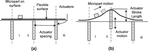
Micropart manipulation techniques are grouped into two broader categories; pick-and-place of individual components using microgrippers and manipulation through various types of workcells. Micromanipulation workcells mostly comprise of discrete microactuators with each actuator directly interacting with the part while the coordinated motion of these actuators generates a resultant output to drive the part from an initial location to a desired destination Citation[1]. The coordination between the actuators is mostly based on sensory feedback and results into controlled actuator movement to reach the desired goal [2,3]Citation2Citation3. Limitations of workcells discussed in the open literature relate to the part size to be handled which could allow the micropart to get stuck between discrete actuators and non-continuous manipulation through direct actuation [4,5]Citation4Citation5. These limitations were overcome on a new approach proposed by the authors that employs a carrier surface with attached actuators Citation[6]. The controlled deformation of the carrier surface by an actuator would generate the controlled motion of a micropart along the surface which is shown schematically for a single actuator in Figure . In the context and discussion in this manuscript, a micropart is considered to have a major dimension of less than 100 μm.
Figure 1 Proposed method for micropart translocation. Part will rest on a flexible skin and the deformation of surface will provide acceleration along the surface and move the part.

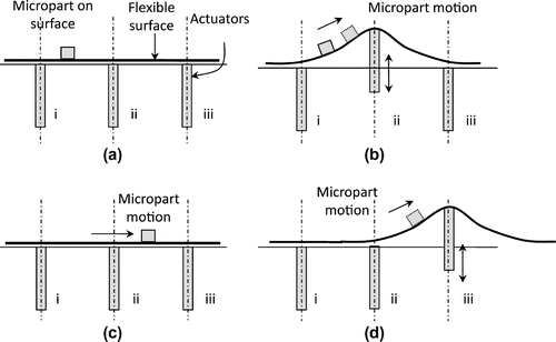
The distance travelled by the micropart is a function of surface deformation wavelength, length of the actuator stroke, actuator time period (or operating frequency), and material and surface characteristics Citation[7]. Specific surface properties and material characteristics yield bounds on the feasible frequency and distance travelled. At frequencies greater than the upper bound the micropart could vertically detach from the carrier surface where at frequencies below the lower bound the micropart could not move at all Citation[6]. Should the micropart be required to translocate a distance greater than the capability of a single actuator, the notion of a microconveyor is introduced through an array of actuators as shown in Figure .
Figure 2 Schematic of actuator array (a) Three actuators with micropart resting on the carrier surface, (b) Actuation of actuator ii deforms the surface causing the micropart to start translating, (c) Actuator ii retracts and the micropart either comes to rest or keeps on translating, and (d) Actuation of actuator iii deforms the surface and causes the micropart to start or keep on translating. Actuators could have different actuation characteristics to control final micropart location.
However, a microconveyor is useful if it could be controlled in order to yield the desired results. As it will be discussed, the dynamics of the micropart motion on the microconveyor are highly nonlinear and discontinuous and as such, the system parameters to be employed for controlling the translocation of a micropart cannot be readily defined. Therefore, the performance of the microconveyor to yield the desired result, that of controlled translocation of a micropart, must be posed as an inverse problem; define the desired performance and identify the system control parameters.
In this work, differential evolution, DE, is used as the optimization tool. DE is a novel developed technique characterized by ease of implementation and use, and its efficiency and robustness Citation[8]. It is beyond the scope of this manuscript to introduce the fundamentals of DE but the interested reader could find more information at the DE web page maintained by Prof. Storn at http://www.icsi.berkeley.edu/~storn/code.html, such as actual code and areas of DE application. DE has been successfully employed in solving many nonlinear programming engineering problems with discrete, continuous and mixed design variables [8–11]Citation8Citation9Citation10Citation11.
In this manuscript, the system and control parameters for controlled translocation of a micropart over a predefined desired distance in minimum time while meeting hardware and physical constraints will be identified. The micromanipulation approach, the modeling and highly non-linear nature of the motion dynamics due to microscale phenomena are introduced. Cautionary steps are also discussed and considered in the definition and implementation of the optimization problem. The development of the implementation logic, design variables and constraints are introduced. The DE performance to identify the design variables while meeting performance specifications through the defined cost function is discussed. The manuscript ends with conclusions.
Proposed micromanipulation approach
The proposed micromanipulation approach is schematically shown in Figure . A micropart (<100 μm representative size) is resting on a carrier surface. A series of actuators is attached at the bottom of the surface as shown in Figure . The actuator motion causes a controlled surface deformation and the high acceleration generated by the controlled actuator motion is transferred to the micropart on the surface. The component of acceleration parallel to the deformed surface at the location of the micropart and the state of the micropart (still or moving) govern the micropart motion along the surface. The acceleration component perpendicular to the surface pushes the micropart vertically and depending on its magnitude could cause the micropart to detach from the surface. The micropart would remain on the surface due to the force of attraction between the carrier surface and the micropart, while the component of inertia force parallel to the surface, if larger than the friction force, could cause the micropart to slide along the surface. A one-dimensional microconveyor platform based upon the concept of active surface comprises of a set of linearly arranged number of actuators.
As the size of the part to be manipulated decreases, the surface force of attraction becomes more dominant compared to the weight [12,13]Citation12Citation13; therefore, in developing the mathematical model for the micropart motion, this force needs to be considered and properly included in the motion dynamics. Various types of surface forces exist including Van der Waal’s effect, capillary force of attraction, and attraction due to contact electrification [13–16]Citation13Citation14Citation15Citation16. The capillary effect and contact electrification can be avoided by controlling the relative humidity in the environment Citation[13] and by grounding the workcell platform respectively, and as such they will not be considered in the current analysis. It is worth noting that these forces could be included in the motion dynamics as needed.
At the microscale, as already mentioned, the effects of the material properties of the micropart and carrier surface and the relative roughness between the two must be considered in deriving the dynamics of the system. A number of microscale friction models have been proposed in the literature. In this work, the Kogut-Etsion, KE, friction model is employed. The KE model accommodates the Van der Waal’s force of attraction between rough surfaces, calculates the repulsion forced between the surfaces due to compression of asperities, and estimates the nonlinear friction force based upon the shear strength of the asperities in contact [17,18]Citation17Citation18. The friction force is evaluated by first estimating the coefficient of friction which is a function of the applied load. The instantaneous value of the coefficient of friction is estimated depending on the value of the normal force between the contacting rough surfaces of the micropart and deformable carrier surface. The surface forces between the micropart and the carrier surface are nonlinear due to the nonlinear variation of the magnitude of friction force at the microscale and the fact that the micropart direction of motion could change with respect to the carrier surface depending on the actuator motion characteristics and the micropart location from the actuator. The instantaneous values of attraction, asperity repulsion and friction forces are estimated according to the KE friction model and are included here to demonstrate the highly nonlinear nature of the system dynamics. Details of the implementation of the KE model along with the dynamics of micropart motion on a carrier surface are discussed in [6,7]Citation6Citation7. These forces are shown in Equations (1)–(3).(1)
(1)
(2)
(2)
Jnc, J and I are given by(3)
(3)
where P is the repulsion force due to the compression of asperities, Fs is the attraction force between the micropart and carrier surface, and Qmax is the shear force supported by the contacting asperities. The other parameters are as follows: d is the mean distance between the two rough surfaces, ωc is the limit of elastic deformation, H is the surface hardness, β (=0.06) is the multiple of asperity density, asperity radius (R) and standard deviation of surface heights (σ), is the intermolecular distance, φz is the asperity probability distribution function, and An is the nominal area of contact between the micropart and carrier surface. K is the hardness coefficient, and θ is the dimensionless adhesion parameter.
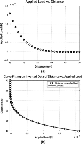
In equations (1) - (4), the mean distance between the two rough surfaces is the input to the system and is used to evaluate the developed forces. However, in a real dynamic situation, this quantity is unknown since it is dynamically changing as a function of the compressing asperities due to the developed forces. For a given input of mean distance and surface and material characteristics, the external load required to maintain the mean displacement between the surfaces equal to the given input displacement can be calculated. In order to utilize the KE model in micropart dynamics, the model must be inverted. However, its highly nonlinear form makes this inversion in symbolic form impossible. This is overcome by generating the applied load data by subtracting the attraction force and contact load curve for a surface of given characteristics. The generated data is automatically curve-fitted to identify a relationship for the mean separation distance between the surfaces as a function of normal applied load; a representative highly nonlinear relationship for a set of input parameters (see Table ) is shown in equation 5 with the separation distance dsep (m) and normal applied load Fn (N).(4)
(4)
Table 1. Design variables types and limits.
Utilizing this equation, the surface force model is inverted, where for any given applied load the mean distance between the surfaces is calculated. Using the known value of mean distance between the two surfaces, the magnitude of the coefficient of friction between the two surfaces is calculated while the direction of the friction force is evaluated considering the state and direction of motion of the micropart. The inversion of surface forces model and associated curve fitting are shown in Figure .
Figure 3 (a) Estimated Applied Load as function of distance between the surfaces in contact and (b) Data Inversion and curve fit.
Using the estimated values of the surface forces, the direction of micropart motion, the direction of friction force, and the stick-slip behavior between the micropart and surface, the dynamics of the micropart are governed by defined motion conditions mathematically presented by Equations (6)–(8). The magnitude and direction of the friction force and the switching between the different modes of motion (stick and slip mode states) adds another component to the nonlinear behavior to the system dynamic model.
The friction force is always opposite to the relative velocity, Vrel, which is the difference between the micropart velocity (Vp) and the surface velocity (Vs), while its magnitude is a function of the micropart state. The friction force is equal in magnitude but opposite to the inertia force along the surface when the relative velocity is zero and it is equal to its maximum value when the micropart is sliding on the surface.(5)
(5)
The relative velocity threshold, Vth, is defined in order to identify the change of the micropart velocity from no relative movement to finite relative velocity and it is a function of the simulation time step (Δt), friction force (Ffriction) and micropart mass (m). In other words, it represents the threshold velocity at which the micropart state changes between slipping along or sticking to the surface.(6)
(6)
The micropart motion along the surface is controlled by a logic scheme according to the following conditions(7)
(7)
where ap is the micropart acceleration while as is the acceleration of the surface. is the maximum value of friction force between the micropart and carrier surface,
is the total force on the micropart. The details of the friction logic algorithm and micropart motion are explicitly discussed and elaborated in the authors’ previous work Citation[6].
In addition, it must be mentioned that the displacement travelled due to a multi-actuator system is not a linear combination of single actuator system behavior or response unless the micropart is allowed to come to rest before a subsequent actuator is engaged. Allowing the micropart to come to rest is a non-desired condition. The engaging velocity of the micropart by a consecutive actuator and the delay time between the activation (or firing) of a consecutive actuator results into a nonlinear output with the direction of friction force adding to the discontinuity in the system equations of motion.
The motion profile of the actuator stroke is assumed to be quintic (5th order equation) that allows jerk control. This is the minimum order motion profile that allows for the definition of initial and final values of position, velocity and acceleration for the actuator stroke. The initial and final values are defined to be(8)
(8)
where h is the height of actuator stroke, L is the maximum length of actuator stroke, v is the velocity of actuator, and is the actuator acceleration; subscripts i and f refer to initial and final values respectively. These values are used to dynamically calculate the constants in the quintic actuator motion profile.
The system of equations for the dynamic evaluation of the attraction and contact forces along with the friction logic is implemented using two coordinate systems. A fixed coordinate system and local coordinate system that moves and orients itself with the micropart movement while keeping the ordinate along the normal to the surface. The details of the micropart motion can be found in Citation[6]. With a predefined time-dependent deformation of the flexible carrier surface through an actuator attached at the bottom of the surface and the input sequence for an array of actuators, the presented equations have no closed-form solution and they must be numerically simulated to estimate the system output. These equations cannot be solved explicitly to estimate the value of system control parameters to achieve a desired output. Therefore, this inverse problem can be solved by employing an evolutionary optimization technique to estimate the best set of controlled input parameters in order to reach a pre-set goal while satisfying certain constraints. This inverse problem is analyzed and solved using differential evolution.
Problem formulation and definition
The optimization problem posed is to find the optimum set of system controlled parameters to translocate a micropart a predefined distance within a certain tolerance while minimizing the required time. The optimization will not only identify the most suitable set of parameters but will also verify the feasibility and functionality of the proposed microconveyor system. A general optimization problem is formulated as finding the values for a set of design variables, , that would minimize a function
, subject to functions of design variable constraints
and boundary constraints
. The design variables are in
,
, and
with
indicating feasible values of integer, discrete and continuous design variables respectively Citation[8].
The general optimization statement is applied to the microconveyor system with the set of design variables selected from the control parameters; minimize the error between the desired location and actual distance travelled by the micropart while minimizing the time of travel and satisfying the design variable and boundary constraints. The design variables are selected to be the control parameters for the simplest operation of a multi-actuator microconveyor system. The design variables defined are the actuator performance specifications, operating frequency and motion stroke, the spacing between the actuators assuming uniform spacing (without loss of generality), and the actuation delay between two consecutive actuators.
The actuation delay is defined to be the time from the end of the reverse stroke of one (first) actuator to the start of the forward stroke of the subsequent (second) actuator and is always greater than zero, i.e. the second actuator starts its motion once the first one comes to rest. A positive value of time delay between the actuator firing will eliminate what we call as “carrier surface deformation overlap” (the combined deformation due to simultaneous actuators). The instantaneous carrier surface deformation value is considered to be only due to a single actuator.
The performance for each actuator to be employed is defined by the controlled parameters of actuator operating frequency and motion stroke. The performance for a pair of consecutive actuators, up to a number for realizing a microconveyor system, is defined by the spacing between the actuators and the time delay for actuating a consecutive actuator relative to the previous actuator. These are controlled parameters and are defined as design variables for optimization purposes. However, without loss of generality, the optimization problem is simplified by reducing the search space and the number of design variables by assuming that the actuator control parameters are the same for each actuator. This implies that all the actuators will operate with the same frequency, same actuator stroke, and that the actuator spacing and delay time between each actuator pair are the same. This simplification reduces the number of design variables to be considered from (4na-2) to 4 with na being the number of actuators; for example for a microconveyor with 5 actuators, the number of design variables reduces from 18 to 4 with the simplification assumption. The physical explanation of the design variables or controlled parameters to be optimized is presented schematically in Figure .
The upper and lower bound constraints for the design variables are based on limits related to hardware capabilities for possible hardware implementation and on previous analysis by the authors in identifying parameters that could cause the micropart to translocate by an individual actuator Citation[6]. The lowest value of the input frequency at 200 Hz is the minimum possible frequency to cause micropart motion with the largest actuator stroke of 200 μm. The upper frequency limit of 10000 Hz is easily achievable with piezoelectric actuators. Note that the actuator frequency is just an indication of how fast the actuator will move in completing only a single stroke and in the proposed approach an actuator does not operate in a repetitive mode but in single actuation stroke.
The actuator spacing is based on the minimum size of a piezoelectric actuator and the maximum value on the distance travelled by a micropart from the individual actuator analysis Citation[6]. The minimum value of actuator spacing is set at 500 μm while the upper limit is defined to be 1500 μm. The deformation wavelength in the analysis is assumed to be 600 μm which is larger than the minimum actuator spacing. The maximum actuator stroke is set to 200 μm, a stroke easily attained with a piezoactuator of approximately 8 to 10 mm length considering a 3% deformation. The minimum value of the time delay between the actuation (firing) of two consecutive actuators is 0 whereas its maximum value is selected high enough to cover the full spectrum of operation.
The constraints on the parameters to be optimized are summarized in Table . All the design variables were defined to be continuous for optimization purposes. The first population generation is generated using random function generator ensuring that the population array covers the entire region of the parameter space with equal probability according to DE theory.
Table 2. Parameters description and values.
Cautionary steps
The solution is evaluated for each population member subject to the constraints. As the solution progresses, if a constraint is violated, the corresponding set of parameters is penalized accordingly and the population of the new generation is created. There are two types of constraints for this problem; the condition that the micropart must be in contact and remain on the surface at all times and the nominal constraints for the design variables.
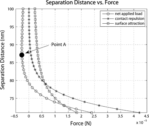
The micropart must remain attached to the surface and as such, its motion is continuously monitored as well as the component of input acceleration perpendicular to the deformed carrier surface. The resultant inertia force perpendicular to the surface is compared at each solution step with the force at the minimum point on the Separation Distance vs. Net Applied Load curve shown in Figure . The net applied load is the difference of the force of attraction between the rough surfaces and the repulsion force between the surfaces as the result of the compression of the asperities. The relative magnitude of these forces along with the Net Applied Load curve is shown in Figure . If the imparted inertia force normal to the surface is larger than the maximum pull force required to separate the micropart from the surface (represented by point A in Figure ), then the micropart state is considered detached. This state is not desirable and if it occurs during the optimization process the set of design variables is penalized.
Figure 5 Separation Distance vs. Force, a negative Applied Load shows that a pull force is required to separate the micropart and the carrier surface.
According to DE theory, during the creation of a new generation by adding the weighted difference of two vectors in a third vector, if a generated design variable falls outside its defined feasible range, this variable is identified in real time. This is addressed during the solution process by resetting its value at a random point within the available bounds Citation[8].
The material properties and the surface roughness parameters used for the numerical simulation are given in Table . The surface contact area and surface roughness are assumed to remain constant. The number of actuators for the microconveyor is assumed to be fixed and for the current optimization an array of five actuators is defined. This number of actuators is large enough that could locate the micropart to a target position of at least 10 mm if a linear combination of individual actuators were employed.
Objective function and cost
The highly non-linear integral form of the friction force, dynamics and inverse equations (1) – (8) used to evaluate the distance travelled by the micropart render the use of traditional deterministic optimization techniques not a good choice for optimization purposes. Thus, an evolutionary based technique, differential evolution, DE, with slight jitter is employed to estimate the optimum values of the design variables to satisfy the objective of controlled translocation of a micropart to a predefined distance within minimum time. DE with slight jitter is added to avoid restricting the solution within possible local minima of the solution space Citation[8].
The micropart is assumed to start from rest and stop at the desired location; thus its initial and final velocities are set to zero. The desired target location is defined to be at 10 mm from the center position of the first actuator while the initial position of the micropart is selected to be at 0.15 mm with respect to the center of the first actuator.
The requirements of the objective function are met by defining a cost function as a combination of the deviation of the distance travelled by the micropart from the desired final location and the total time taken for the motion. The time is in units of seconds whereas the displacement is in meters. In order to generate a suitable cost function from these two parameters having different units, the final value of the micropart deviation from the target position is normalized with an acceptable tolerance Td. To ensure that the final position of the micropart is within a defined tolerance from the target, the effect of normalized deviation is amplified by raising it to a large power C. If the deviation of the final position of the micropart is within the predefined tolerance, the normalized deviation will be less than 1 and its effects will be greatly attenuated with the large power (C) resulting in a very small contribution to the overall cost. Contrary, if the micropart final location is outside the tolerance region, the normalized deviation will be greater than 1 and the violation effects in the cost function are amplified since they are raised to a large power (C).
As mentioned, the micropart must remain in contact and on the carrier surface at all times during the translocation otherwise the micropart is considered detached from the surface. During the optimization process, if the values for a set of design variables for a population member result in detachment, the population member is penalized with a fixed cost of 105.
The travel time is included in the cost function with a simple multiplier weight A that is set according to the overall travel time of the micropart movement. In the current approach, the travel time is of the order of 0.1 sec. In order to add a significant contribution by the travel time in the cost function, and in fact the only contribution if the micropart is within the allowable positioning tolerance limit, the constant A must be set at an appropriate high number. The final form of the cost function is shown in equation 11.)
where A and C are constants, tf is total time for the micropart to reach the final position, Ltol the desired tolerance for the micropart placement, Xf is the final location of micropart, and Xfd is the desired final position.
Analysis Results and Discussion
The presented cost function is minimized by employing the DE algorithm with 50 population members, 50 total generations, a crossover probability of 0.8, and a step size of 0.9. The crossover probability is kept high in order to generate the new combination of the population members and avoid local minima due to the high discontinuity of the solution space. The values for the constants A and C are 500 and 20 respectively. The desired tolerance range is set at ±20 μm from the target position of 10 mm.
The DE optimization was performed using the defined parameters and constraints. The micropart translocates to a distance of 10.015 mm which is within the tolerance range from the target position. The converged results are shown in Table . These results are within the defined parameter limits and constraints.
Table 3. Converged values of design parameters.
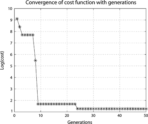
The convergence of the cost function as function of the number of iterations is shown in Figure . The initial cost is very high, in the order of 109, with a major contribution due to the deviation of the location tolerance constraint. The final cost is 18.5. The micropart reaches the desired location within the defined tolerance limit of ±20 μm of the target with almost all the cost contributor being due to the required time.
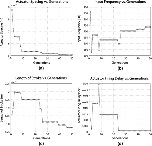
The convergence for each design variable as a function of the generations is shown in Figure . It is observed that an input frequency of approximately 700 Hz with a small actuator stroke length is preferred as compared to a lower frequency with a larger stroke length; the actuator frequency (actuator motion time) contributes to the time it takes for the micropart to reach its final desired location so the faster the actuator operates the quicker the micropart will reach its destination. This does not imply that the actuator should operate at the highest defined limit since at very high frequencies the micropart could detach from the carrier surface. It is also observed that the time delay between consecutive actuators is minimized thus minimizing the required time to complete the translocation motion.
Figure 7 Convergence of design variables as function of generations: (a) Actuator spacing, (b) Input frequency, (c) Length of stroke, and (d) Actuator firing time delay.
The estimated optimum values of the design variables were used as inputs to simulate the motion of the micropart. The micropart motion velocity and motion trace profile are plotted in Figure . The micropart velocity as function of time is shown in Figure where the interaction of micropart with the first three actuators in the array is at 0.0 sec, 0.0023 sec and 0.0041 sec. The second actuator is timed to engage the moving micropart (motion initiated due to the first actuator) and upon engagement to accelerate it in order to further increase its velocity and eventual travel distance without causing detachment. The micropart interacts with the carrier surface deformation caused by the third actuator which slightly reduces its velocity. It is important to mention here that depending on the desired final location of the micropart additional actuators might be required. The constant decrease in velocity is due to the constant value of the friction force between the micropart and surface which eventually brings the micropart to rest within the desired tolerance range.
Figure 8 Micropart motion (a) Variation of horizontal component of velocity with time and (b) Trajectory of micropart motion profile in X–Y plane.
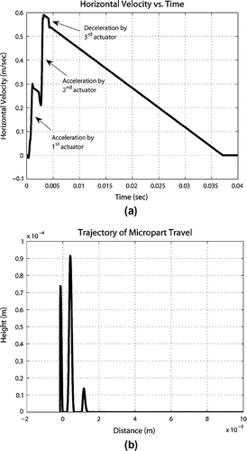
The trace of the micropart motion profile in the X-Y plane is shown in Figure where the X-axis represents the linear displacement (or distance travelled) and the Y-axis represents the height on the carrier surface due to surface deformation; note that the Y-axis scale is one order of magnitude smaller than the X-axis. The three humps represent the interaction of the first three actuators with the micropart. In the 2-D trajectory of the micropart in Figure , during the interaction of the micropart with the deformation due to each individual actuator, the vertical location of the micropart is variable and its maximum value of 92 μm is less than the converged stroke of 178 μm. This difference is due to the fact that the micropart is not at the same location as the actuator when the actuator is at its fully extended length, but it is at some other location on the carrier surface. The micropart stops at a distance of 10.015 mm which is within the tolerance range of ±20 μm from the target position of 10 mm while requiring only 0.037 sec to complete the motion.
Conclusions
Active surface for micropart manipulation requires the placement of micro actuators in the form of an array to move the micropart from the given position to a required target position. While arranged in the form of an array, the downstream actuators could engage the micropart while moving with an initial velocity. Depending on the instantaneous location and initial velocity, the actuators can accelerate and/or decelerate a moving micropart. An optimization approach was successfully employed to estimate the design variables for controlled micropart manipulation with actuator arrays for a desired goal with a predefined tolerance while minimizing the time for accomplishing the task and without violating the constraints. The optimized set of design variables takes full advantage of the acceleration and deceleration capability of actuators where the first two actuators accelerate the micropart while the third actuator decelerates it. Though consecutive actuators in the form of an array is a discontinuous problem which does not have a closed form solution in the forward direction, the inverse of the problem can be solved using an optimization method such as DE, and a set of design variables can be estimated to reach a desired target position. Moreover, it has been shown that placing actuators in a sequential array at discrete locations a continuous microconveyor platform could be realized to controllably translocate microparts at distances beyond the capability of a single actuator.
Acknowledgements
The authors would like to thank the reviewers for their constructive comments that improved the manuscript from its original form.
References
- K.F. Bohringer, B.R. Donald, R. Mihailovich, and N.C. MacDonald, A theory of manipulation and control for microfabricated actuator arrays, Proceedings of IEEE Workshop on Micro Electro Mechanical Systems, MEMS’94; Oiso, Japan; 1994, pp. 102–107.
- H. Fujita, M. Ataka, and S. Konishi, Cooperative work of arrayed microactuators, IECON’94 20th International Conference on Industrial Electronics, Control and Instrumentation, Vol. 3; Bologna, Italy; 1994, pp. 1478–1482.
- Fromherz MPJ, Jackson WB. Force allocation in a large-scale distributed active surface. IEEE Transactions on Control Systems Technology. 2003;11(5):641–655.
- T. Furuhata, T. Hirano, and H. Fujita, Array-driven ultrasonic microactuators, Solid-State Sensors and Actuators, Digest of Technical Papers, International Conference on Transducers; San Francisco, CA; 1991, pp. 1056–1059.
- Bohringer KF, Donald BR, MacDonald NC, Kovacs GTA, Suh JW. Computational methods for design and control of MEMS micromanipulator arrays. IEEE Computational Science and Engineering. 1997;4(1):17–29.
- Rizwan M, Shiakolas PS. Motion analysis of micropart in dry friction environment due to surface excitation considering microscale forces. ASME Journal of Tribology. 2011;133(4):041405–1–041405–12.
- M. Rizwan, A one dimensional dry friction microconveyor platform: Modeling and analysis of micropart motion due to surface excitation, Ph,D, diss., The University of Texas at Arlington, 2011.
- Price KV, Storn RM, Lampinen JA. Differential Evolution: A Practical Approach to Global Optimization. New York, NY: Springer-Verlag; 2005.
- B. Babu, and R. Angira, Optimization of non-linear functions using evolutionary computation, Proceedings of the 12th ISME International Conference on Mechanical Engineering, India, 2001, pp. 153–157.
- Shiakolas PS, Koladiya D, Kebrle J. On the optimum synthesis of four-bar linkages using differential evolution and geometric centroid of precision positions. International Journal of Inverse Problems in Engineering. 2002;10(6):485–502.
- Shiakolas PS, Koladiya D, Kebrle J. Optimum robot design based on task specifications using evolutionary techniques and kinematic, dynamic, and structural constraints. International Journal of Inverse Problems in Engineering. 2002;10(4):359–375.
- Rollot Y, Regnier S, Guinot JC. Simulation of micro-manipulations: Adhesion forces and specific dynamic models. International Journal of Adhesion and Adhesives. 1999;19(1):35–48.
- Zhou S-A. On the forces in microelectromechanical systems. International Journal of Engineering Science. 2003;41(3–5):313–335.
- G. Li, Y. Peng, and X. Zhang, Analysis of micro-forces between micro-parts and their influence factors in MEMS, , 2008.
- Lowell J, Rose-Innes A. Contact electrification. Advances in Physics. 1980;29(6):947–1023.
- R.S. Fearing, Survey of sticking effects for micro parts handling, Intelligent Robots and Systems: Human Robot Interaction and Cooperative Robots’, Proceedings of 1995 IEEE/RSJ International Conference, Vol. 2, 1995, pp. 212–217.
- Kogut L, Etsion I. A finite element based elastic-plastic model for the contact of rough surfaces. ASME Journal of Tribology. 2003;46(3):383–390.
- Kogut L, Etsion I. A static friction model for elastic-plastic contacting rough surfaces. ASME Journal of Tribology. 2004;126(1):34–40.
- Greenwood J, Williamson J. Contact of nominally flat surfaces. Proceedings of the Royal Society of London, Series A, Mathematical and Physical Sciences. 1966;295(1442):300–319.
- Chang W, Etsion I, Bogy D. An elastic-plastic model for the contact of rough surfaces. ASME Journal of Tribology. 1987;109(2):257–263.
