Abstract
The present authors proposed the electric potential computed tomography (CT) method for identifying defects in electric-conductive bodies from electric potential distributions observed on their surfaces under electric current application. When the piezoelectric material is pasted on a cracked body subjected to mechanical load, the electric potential distribution can be obtained due to the direct piezoelectric effect without applying the electric current. The passive electric potential CT method proposed by the present authors uses this distribution. This paper describes the fundamentals of the passive electric potential CT method, inverse analysis schemes and its applications for identification of a through-thickness crack, a surface crack, plural cracks and delamination in a layered composite material. The usefulness of the method is demonstrated.
1. Introduction
Inverse problems have been receiving attention in various fields of science and engineering. An increasing number of books and review papers have been published on inverse problems.Citation[1–9] The definition and categorization of inverse problems are given by the present authors.[6,7] The detection and identification of defects and cracks can be categorised into domain/boundary inverse problems. The present author proposed the active electric potential computed tomography (CT) method Citation[10–12] for the detection of defects from electric potential distribution on the surface of cracked body under electric current application. The applicability of the method has been shown numerically and experimentally.
When the piezoelectric film is pasted on the surface of a cracked body subjected to mechanical load, change in electric potential distribution is observed on the surface of the film. Based on this phenomenon, the present authors proposed the passive electric potential CT method Citation[13,14] which did not require electric current application for identifying cracks. This method may be applied to develop an intelligent structure with a function of self-monitoring of defects. For identifying defects from the electric potential distribution on the piezoelectric film, an inverse method based on the least residual method was applied, in which square sum of residuals are evaluated between the measured electric potential distributions and those computed by using the finite element method. In the present paper, the fundamentals of the passive electric potential CT method using a piezoelectric material and its applicability are demonstrated.
2 Categorization of inverse problems
The present authors defined the inverse problems as the problems which cannot be categorised into direct problems.Citation[6,7] Then a rational definition of inverse problems can be given by referring to the definition of direct problems.
For example, consider an analysis of distribution of a physical quantity . The following information is indispensable for conducting a direct analysis of distribution of the physical quantity
.
| a. | Domain Ω, where | ||||
| b. | Governing equation of the variation of the physical quantity | ||||
| c. | Boundary conditions defined on boundary Γ and initial conditions in domain Ω, if necessary. | ||||
| d. | Source term f defined in domain Ω. | ||||
| e. | Distribution of material properties κ defined in domain Ω. | ||||
When all information of these items is available, we can obtain output or response using analytical schemes or conventional numerical schemes, such as the finite element method, the boundary element method and the finite difference method.
If one of requisites (a) to (e) is missing, we cannot conduct a direct analysis that determines the distribution of physical quantity in domain Ω.
For the problem associated with the distribution of , there are the following inverse problems corresponding to the lack of requisites (a) to (e) for the direct analyses.
| A. | Estimation of the shape of domain Ω, its boundary Γ or unknown inner boundary (domain/boundary inverse problems). | ||||
| B. | Inference of the governing equation or the operator L (governing equation inverse problems). | ||||
| C. | Estimation of the boundary conditions on the entire boundary Γ or its partial boundary, and/or estimation of the initial conditions in Ω (boundary value/initial value inverse problems). | ||||
| D. | Estimation of source f applying in Ω (source inverse problems). | ||||
| E. | Estimation of material properties κ defined in Ω and involved in the governing equation (material properties inverse problems). | ||||
Any combination of these inverse problems can be another inverse problem. This categorization has been used frequently.Citation[15]
The inverse problems are inherently lacking in information as compared with direct problems. Additional information is necessary to conduct inverse analyses for inverse problems. Output or response can be used as primary information to conduct inverse analyses. This is contrary to the direct problem, in which output or response is determined from input. The information concerning output or response can be obtained by measurements, for example. A priori information, such as physical constraints or knowledge based on experience about the input, can be effectively used in the inverse analyses. This kind of information can be called the secondary information or subsidiary information.
3 Active electric potential CT method for crack identification
In evaluating the integrity and fitness of structures and their components, nondestructive inspection of defects is very important. The inspection can be regarded as one of the domain/boundary inverse problems, since defects correspond to unknown inner boundaries to be estimated from certain observations. Ultrasonic inspection, eddy current method, A.C. electric potential method, D.C. electric potential method, radiation method, elastodynamic response and strain measurement have been used for the inspection.
The present authors proposed the active electric potential CT (computed tomography) method for the detection and quantitative identification of cracks.Citation[10–12] In this method, the electric potential distributions observed on the surface of cracked body under active electric current application is used to identify the cracks, as is shown in Figure .
Figure 1 The active electric potential CT method for crack identification.
For the crack identification, the inverse boundary integral equation method and the least residual method were proposed. In the least residual method, a quasi-solution of a crack is searched, which gives the minimum residual R between the observed and computed potential readings among admissible cracks. The present authors discussed the condition for the uniqueness of the inverse solution in crack identification from measured electric potential distribution on flux-free boundary. To ensure the uniqueness of the crack identification, the multiple current application method was proposed, in which electric potential data measured under several current application conditions were processed simultaneously.
Numerical simulations and experiments were conducted. The applicability of the least residual method was demonstrated in estimating the crack location, size and shape of two- and three-dimensional cracks.Citation[10]
4 Passive electric potential CT method for crack identification
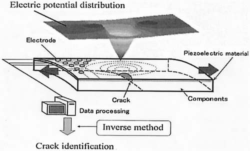
Electrical charge proportional to a change in mechanical strain is incurred on piezoelectric material. When the piezoelectric film is pasted on cracked body, which undergoes mechanical load, electric potential distribution is incurred on the film due to the piezoelectric effect without applying the electric current on the cracked body, as is shown in Figure . The passive electric potential CT method uses this incurred electric potential.Citation[13,14] The finite element method can be applied to calculate the electric field on the piezoelectric film as well as the deformation field.
Figure 2 The passive electric potential CT method for crack identification.
The governing equations of the piezoelectric material can be written as follows Citation[13]:(1)
(2) where {σ} and {ϵ} are stress and strain vector, [C], [e] and [g] are stiffness matrix, piezoelectric coefficient matrix and dielectric constant matrix, respectively. {E} is electric field vector. {D} is electric displacement vector. The static FEM equation, based on Equations (1) and (2), is obtained as
(3) where [Kuu], [Kuϕ] and [Kϕϕ] are the mass matrix, displacement electric stiffness matrix and electric stiffness matrix, respectively. {F} and {Q} are the mechanical load vector and the electric load vector, respectively.
The FEM computer analysis scheme was developed for calculating the electric potential distribution on the film taking the coupled elastic and electric effect into consideration.
As the inverse analysis method for identification of cracks, the least residual method was applied. In this method, computed electric potential value (c) is compared with the measured value
(m) to determine the most plausible crack location and size. As a criterion for crack identification, the following square sum R of residual is calculated.
(4)
Here denotes measured electric potential value at the ith measuring point, and
denotes the electric potential values at the ith measuring point computed by the FEM for an assumed combination of crack parameters. M is the total number of measuring points. The combination of crack parameters, which minimised R, was employed as the best estimation.
For effective inverse analysis, a hierarchical calculation that consisted of a rough estimation of crack parameters and a detailed estimation using optimization scheme were introduced. In the rough estimation, R was approximated by a quadratic equation, which was convenient to obtain parameters giving the minimum value of R. In the detailed estimation, the modified Powell method was applied. The estimated crack parameters obtained in the rough estimation were used as the initial values of the optimization.
5 Application of the passive electric potential method for crack identification
The passive electric potential CT method was applied for the identification of various cracks, as is described below.
5.1 Identification of through-thickness cracks
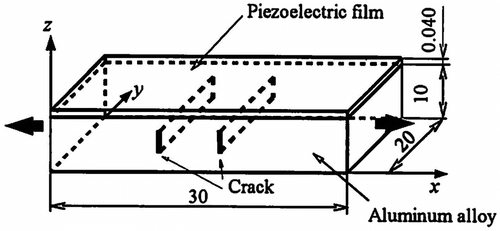
The passive electric potential CT method was applied for the identification of through-thickness cracks shown in Figure .Citation[16] The piezoelectric poly vinylidene fluoride (PVDF) film was pasted on the specimen. When the specimen is subjected to mechanical load of 3920(N), a change in electric potential distribution was observed on the surface of PVDF film.
Figure 3 A specimen with a through-thickness crack and a piezoelectric film.Citation[16]
![Figure 3 A specimen with a through-thickness crack and a piezoelectric film.Citation[16]](/cms/asset/03c024ab-45d6-47ea-a46f-f281de025401/gipe_a_782544_f0003.gif)
Figure shows an example of electric potential distributions on the piezoelectric PVDF film measured using a non-contact method, which did not require electric charge transfer and therefore was accurate. As is seen in the figure, there are two peaks in electric potential distributions. The height of the peaks and the spacing between peaks depend on crack length a, and crack depth h defined as the distance from the top surface to the upper tip of the crack. The point of the local minimum of electric potential roughly coincides with the location of crack in the x-direction, xc. The value of electric potential is in the order of 10 V. These distributions agree well with calculated ones under the boundary condition and loading condition, which is same with the experiment.
Figure 4 Electric potential distribution measured on piezoelectric film pasted on the surface of specimen with through-thickness crack.Citation[16]
![Figure 4 Electric potential distribution measured on piezoelectric film pasted on the surface of specimen with through-thickness crack.Citation[16]](/cms/asset/ddcf3755-f67f-48ed-94c9-ee391ee8d0c9/gipe_a_782544_f0004.gif)
Table shows an example of the crack parameters estimated by the hierarchical inverse analysis scheme from electric potential distribution obtained by the non-contact measurement. As is seen in the table, the estimated crack parameters agree well with the actual ones.
Table 1. Crack parameters estimated from measured electric potential distribution on the piezoelectric film.
5.2 Identification of plural cracks
The passive electric potential CT method was applied to the identification of plural cracks shown in Figure .Citation[17] When the two cracks are located apart, there are 4 peaks in the electric potential distribution, since two peaks appear in the electric potential distribution for a single crack. When the two cracks are closely located, an interaction of the distributions for two cracks resulted in the reduction in the number of peaks.
Figure 5 Specimen with plural cracks.
The identification of the cracks in the interaction of electric potential distribution was made by using the least residual method. For judging whether the number of cracks is two or one, the Akaike information criterion (AIC) Citation[18] was introduced. AIC is defined by the following equation.(5)
Here, N denotes the total number of measurements and P is the number of the crack parameters.
An example of the crack identification is shown in Table for the measurement noise level of 0.5%. The AIC value assuming that there are plural cracks is smaller than that of assuming that there is one crack, showing that the estimated number of crack is two. The estimated values of crack length a, crack depth h and crack locations x1c and x2c of the plural cracks agree well with the actual ones. Thus, the location and size of the cracks can be estimated with good accuracies by the passive electric potential CT method even in the existence of measurement errors up to 3%.Citation[17]
Table 2. Crack parameters of the plural cracks estimated by the passive electric potential CT method.[17]
5.3 Identification of surface cracks
The passive electric potential CT method was applied for the identification of surface crack shown in Figure .Citation[19] An example of electric potential distribution on the piezoelectric film is shown in Figure . A characteristic electric potential distribution is found. The shape of the distribution agrees well with the calculated one for the same boundary condition and loading condition.
Figure 6 Specimen with a surface crack.Citation[19]
![Figure 6 Specimen with a surface crack.Citation[19]](/cms/asset/46675ed3-c0ef-4856-9474-86147843546c/gipe_a_782544_f0006.gif)
Figure 7 Measured electric potential distribution on the piezoelectric film pasted on specimen with a surface crack.Citation[19]
![Figure 7 Measured electric potential distribution on the piezoelectric film pasted on specimen with a surface crack.Citation[19]](/cms/asset/e293fe46-f6f7-4a75-98ac-574618025b8d/gipe_a_782544_f0007.gif)
Figure shows the estimated crack and the actual one by a solid line and a dashed line, respectively. As is seen in the figure, the estimated crack agrees well with the actual one.
Figure 8 Surface crack estimated from the measured electric potential distribution.Citation[19]
![Figure 8 Surface crack estimated from the measured electric potential distribution.Citation[19]](/cms/asset/9ac060cf-f6fb-4e06-9b29-ec82ca6af4e7/gipe_a_782544_f0008.gif)
5.4 Identification of delamination in layered composite material
The passive electric potential CT method was applied for the identification of delamination in a composite material.Citation[20] Since loading in the longitudinal direction gave no change in strain and electric potential distributions from those without delamination, the three-point loading was applied as is shown in Figure . Under the three-point loading, local peaks appeared in the electric potential distribution around the delamination fronts. The estimated location and depth of delamination agreed well with the actual ones.
Figure 9 Identification of delamination in composite material under three-point bending.Citation[20]
![Figure 9 Identification of delamination in composite material under three-point bending.Citation[20]](/cms/asset/d0222096-fa18-4f8e-abe4-3a73b4412d0d/gipe_a_782544_f0009.gif)
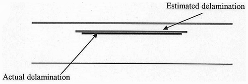
An example for identification of the delamination is shown in Figure . As is seen in the figure, good estimation of delamination size and location is made.
Figure 10 Delamination identified by the passive electric potential CT method.
By applying electric pulse to the piezoelectric film, supersonic wave is activated and reflected waves can be observed by using the piezoelectric film. The active pulse-echo method uses this technique.Citation[21,22] The active pulse-echo method is useful for identification of the crack located far from the film, while it is not applicable for identification of subsurface crack. On the contrary, the passive electric potential CT method is effective for the identification of the crack near the film surface, while its accuracy deteriorates with the distance between the film and crack. Then, the simultaneous use of the passive electric potential CT method and the active pulse-echo method was examined.Citation[23]
6 Conclusions
By using the electric potential distribution appearing passively on the piezoelectric film pasted on a cracked body subjected to mechanical load, the passive electric potential CT method was proposed for the identification of crack. The fundamentals of the passive electric potential CT method and inverse analysis schemes were described. The applicability of the passive electric potential CT method for identification of a through-thickness crack, a surface crack, plural cracks and delamination in a layered composite material was demonstrated.
Table
Acknowledgement
This work was partly supported by the Ministry of Education, Science, Sports and Culture, Japan under the Grant-in-Aid for Scientific Research.
References
- Tikhonov AN, Arsenin VY. Solutions of ill-posed problems. New York: V.H. Winston; 1977..
- Gladwell GML. Inverse problems in vibration. Dordrecht: Martinus Nijhoff; 1986..
- Lavrent'ev MM, Romonov VG, Shishatskii SP. Ill-posed problems of mathematical physics and analysis. Providence, RI: Amer. Math. Soc.; 1986..
- Romanov, VG, 1987. Inverse problems of mathematical physics. Utrecht: VNU Sci Press; 1987.
- Groetsch CW. Inverse problems in the mathematical sciences. Braunschweig: Vieweg; 1993..
- Kubo S, Ohji K. Applications to inverse problems. Application of the boundary element method (in Japanese). Tokyo: Corona; 1987. p. 181–198..
- Kubo, S, 1988. Inverse problems related to the mechanics and fracture of solids and structures, JSME Int. J., Ser. I Jpn. Soc. Mech. Engrs. 31 (1988), pp. 157–166.
- Kubo S. Inverse problems (in Japanese). Tokyo: Baifukan; 1992..
- Kubo S. Thinking Inversely and Solving Inversely (in Japanese). Tokyo: Ohm; 1997..
- Kubo S, Sakagami T, Ohji K. Electric potential ct method for measuring two- and three-dimensional cracks. Current Japanese Materials Research. Vol. 8. Fracture Mechanics, Soc. Mat. Sci., Jpn. Elsevier, 1991. p. 235–254..
- Kubo S, Sakagami T, Ohji K. Electric potential CT method based on BEM inverse analyses for measurement of three-dimensional cracks. Computational Mechanics’86. Springer; Vol. 1, 1986. p. V-339–V-344..
- Kubo S, Sakagami T, Ohji K. Reconstruction of a surface crack by electric potential CT method. Computational Mechanics’88 Springer; Vol. 1, 1988. p. 12.i.1–5..
- Li, SQ, Kubo, S, Sakagami, T, and Liu, ZX, 2000. Theoretical and numerical investigations on crack identification using piezoelectreic material-embedded structures, Mater. Sci. Res. Int. 6 (2000), pp. 41–48.
- Shiozawa, D, Kubo, S, and Sakagami, T, 2004. Passive electric potential CT method using piezoelectric material for crack identification, Inverse Prob. Sci. Eng. 12 (2004), pp. 71–79.
- Dulikravich GS, Thomas JM, Dennis BH. Multidisciplinary Inverse Problems. In: Proceedings of the Inverse Problems in Engineering, Theory and Practice, 3rd International Conference on Inverse Problem in, Engineering; 1999. p. 1–8..
- Shiozawa, D, Kubo, S, and Sakagami, T, 2004. An experimental study on applicability of passive electric potential CT method to crack identification, JSME Int. J., Ser. A 47 (2004), pp. 419–425.
- Shiozawa, D, Kubo, S, Sakagami, T, and Takagi, M, 2006. Passive electric potential CT method using piezoelectric material for identification of plural cracks, Comput. Model. Eng. Sci. 11 (2006), pp. 27–36.
- Akaike, H, 1978. A new look by the Bayes procedure, Biometrica 65 (1978), pp. 53–59.
- Shiozawa, D, Kubo, S, and Sakagami, T, 2006. Experimental study on applicability of passive electric potential CT method for identification of three-dimensional surface crack, JSME Int. J., Ser. A 49 (2006), pp. 426–435.
- Nakatani, K, Kubo, S, Sakagami, T, Shiozawa, D, and Takagi, M, 2007. An experimental study on the identification of delamination in a composite material by the passive electric potential CT method, Measure. Sci. Technol. 18 (2007), pp. 49–56.
- Kubo S, Sakagami T, Suzuki T, Maeda T, Nakatani K. Use of the piezoelectric film for the determination of cracks and defects – the passive and active electric potential CT method. J. Phys. Conf. Ser. 2008;135:1–9..
- Kubo, S, Sakagami, T, and Suzuki, T, 2012. Multiple electrodes active pulse echo method using a piezoelectric film for crack identification, J. Solid Mech. Mater. Eng., JSME 6 (2012), pp. 519–529.
- Kubo S, Sakagami T, Ioka S, Tsuboi K. Effect of combination of passive and active electric potential CT methods using piezoelectric film on crack identification. In: Proc. CST2010: 10th International Conference on Computational Structures Technology, Paper #65. p. 1–12, 2010..