Abstract
Smart materials structures with multifield coupling properties have been widely used in the latter years. Some methodologies have been developed to study fracture problems in piezoelectric and magnetoelectroelastic (MEE) materials using the boundary element method (BEM). However, relatively limited attention has been paid to inverse problems. Identification problems are usually ill-conditioned, which implies that gradient search methods might not have a good performance, whilst Newton-based search methods are computationally expensive. Additionally, the presence of noise in the measured data affects the convergence of these methods. In this paper, we study the application of neural networks to damage identification of multifield materials, in particular to MEE materials. A particular training set division has been applied to improve the identification results, even for high noise levels. A hypersingular BEM is used to obtain the solution of the direct problem (elastic displacements and magnetic and electric potentials) and create the training set.
Introduction
Smart or multifield materials have gained special attention in latter years due to their ample range of applications, from sensors in structural health monitoring to transducers in medical devices. Such applications take advantage of their coupling properties among different fields: mechanical and electric in piezoelectric materials; mechanical, electric and magnetic in magnetoelectroelastic (MEE) materials. Many of these materials exhibit brittle behaviour, which means damage is susceptible to appear, due to operating conditions or even during the manufacture process. This issue has encouraged several authors to analyze the behaviour of these materials analytically [Citation1–Citation4] or numerically,[Citation5–Citation8] to cite a few works. However, little attention has been given to damage identification in smart materials.
Damage identification is a ramification of inverse problems.[Citation9] Several numerical or analytical formulations have been proposed in the literature (see e.g. [Citation10–Citation12]). Nowadays, ordinary methods are gradually being replaced by artificial intelligent techniques to model damage identification, since they do not require a speficic inverse formulation of the problem. Instead, these methods use the solution of the direct problem, i.e. the effect of the damage in the response, to model the inverse problem. With this objective, Comino et al. [Citation13] introduced genetic algorithms and topologic derivatives to solve inverse problems in anisotropic plates. Lu et al. [Citation14] applied neural networks (NNs) to identify cracks in aluminium plates. A large list of authors could be cited for structural damage identification. Nevertheless, the references are limited when it comes to damage identification in smart materials: in reference [Citation15], genetic algorithms and the finite element method were used to identify holes in piezoelectric ceramics, while in [Citation16] probabilistic theory was applied for damage identification. To the authors’ best knowledge, no work for damage identification in MEE materials has been presented so far.
The objective of the present study is to analyse the application of the NNs in damage identification of MEE materials. For this purpose, the formulation by García-Sánchez et al. [Citation17] for 2D static fracture analysis of MEE materials is employed to solve the direct problem for different sizes, position and crack orientations. These data are used as input to a back-propagation NN.[Citation18] A trained NN will identify the crack location of the input data, and should be able to identify cracks of non-trained inputs. The noise sensitivity of the NN was also verified.
This paper is organized as follows. The governing equations of MEE materials are stated in Section 2. The direct problem is described in Section 3 and the inverse problem is depicted in Section 4. The obtained numerical results are shown in Section 5. Concluding remarks are presented in Section 6.
MEE governing equations
The linear MEE 2D problem can be represented in an elastic-like way by generalizing Barnett and Lothe’s approach [Citation19] for piezoelectric materials. An extended displacement vector is defined that includes the elastic components
, the electric potential
and the magnetic potential
, as
(2) where the lowercase subscripts vary from 1 to 2, whereas the uppercase ones take the values 1,2 (elastic), 4 (electric) and 5 (magnetic). A generalized stress tensor
can also be defined as
(3) with an associated generalized traction vector
(4) where
represents the mechanical stress tensor,
are the components of the electric displacement,
stands for the components of the magnetic induction vector, and
are the components of the normal vector to the boundary.
The MEE constitutive equations may them be written as [Citation20](5) where the material properties have been grouped together into a generalized elasticity tensor
defined as
(6) with
,
,
,
,
and
being the elastic stiffness, the dielectric permittivities and the magnetic permeabilities tensors, and the piezoelectric, the piezomagnetic and the electromagnetic coupling coefficients, respectively.
Direct boundary element method (BEM) formulation for crack problems in MEE materials
Linear elastic fracture mechanics is one of the areas where the BEM has clearly demonstrated being a powerful and effective numerical method when compared to other computational techniques. Among its advantages one may cite that: (i) discretization of only the boundary is required; thus simplifying preprocessing and remeshing in crack growth analysis, (ii) it shows improved accuracy in stress concentration problems, since there are no approximations imposed on the stress solution at the interior domain points, or (iii) fracture parameters (stress intensity factors, energy release rates, etc.) may be accurately determined from the computed nodal data in a straightforward manner.[Citation21, Citation22]
The training data set for the NN will be generated from numerical simulations performed using the dual BEM formulation proposed by García-Sánchez et al. [Citation17] for 2D static fracture problems of MEE materials. This approach will be implemented to solve the corresponding direct problem for different cracks with varying sizes, locations and orientations.
Let be a 2D MEE-cracked domain with boundary
, so that
, where
are two geometrically coincident crack surfaces and
denotes the rest of the (crack-free) boundary. The dual formulation of the BEM makes use of both the generalized displacement boundary integral equation (BIE)
(7) and the generalized traction BIE
(8) to overcome the difficulty imposed by having two coincident crack boundaries that would lead to a degeneracy in case of considering only the standard displacement BIE. In Equations (6) and (7),
and
stand for the fundamental solution displacements and tractions, respectively;
and
follow from differentiation of
and
and further substitution into the constitutive Equation (4);
are the free terms arising from the Cauchy principal value integration of the fundamental solution kernels. Equations (6) and (7) hold in the absence of generalized body forces, eletric charge density and electric current density.
Further details about the BEM formulation and its validation are given in [Citation17], where aspects like meshing strategy, implemented fundamental solutions, evaluation of fracture parameters and integrations schemes are explained thoroughly. In particular, the BEM formulation in [Citation17] is detailed for cracks that are self-equilibrated from a mechanical point of view and are electrically and magnetically impermeable, i.e.(9) where the superscripts
and
stand for the upper and lower crack surfaces, respectively. In such cases, it suffices to apply the displacement BIE for collocation nodes on
and the traction BIE for collocation nodes on either face of the crack, say
(10) to yield a complete set of equations to compute the generalized displacements and tractions on
and the generalized crack opening displacements
on
. In Equation (10), the free term is set to 1 because of the additional singularity arising from the coincidence ot the two crack surfaces.
Inverse problem
Several techniques have been developed in order to solve different types of inverse problems.[Citation23] Analytical techniques are very effective but can only be applied for simple configurations. Moreover, due to ill-conditioning, there is no guarantee of a (unique) solution to the problem.
When the behaviour of the physical system is too complex or not entirely known, a black box model may be chosen to represent the inverse problem. For this purpose, the NNs were widely used in structural inverse problems,[Citation24] damage identification,[Citation14, Citation25] or parameters estimation,[Citation26] among many applications.
An artificial NN is a system made by numerous simple structural units called neurons, that are arranged in layered structures. The particular properties of the NN include a parallel way to process information and the learning by experience feature, which allows the NN to reutilize the acquired experience. The NN can be trained to have a specific function through the adjustment between the neurons connections.[Citation18]
We consider a back-propagation NN scheme, as Figure sketches. The output of the NN is given by(11) where
represents the weights linkage between the
th neuron of the
th layer and the
th input,
is the transfer function, defined as
(12) with exp as the exponential function. Let us remark that Equation (12) can be repeated recursively for
until the input layer, where
is replaced by the network input
. The NN output error
is defined as
, where
is the target parameter.
The mean square error (MSE) is defined as the sum of all quadratic errors for all neurons of the output layer, for every
input of the training set, and it is expressed by
(13) The training rule is based on the minimization of the MSE, reducing the error until some acceptable tolerance. In this work the Levenberg–Marquardt algorithm is applied as training rule (see [Citation27] for details).
Next both a standard NN and an improved NN with training set division (TSD) will be implemented and their performance analysed on a practical crack identification example.
Fig. 1 Scheme of the a back-propagation NN.
Numerical results and discussion
Analysed problem
A square 2D plate with dimensions cm of a MEE
composite with a volumetric fraction of
is considered in this work. The material properties are given in Table . The crack parameters range is summarized in Table , where
and
indicate the crack center,
denotes the crack length and
represents the crack orientation with respect to the
direction, as shown in Figure . In what follows the crack center coordinates (
) are normalized dividing their respectives values by the plate length
, obtaining a
-to-
scale in function of the plate side dimension. The crack length is normalized in
, to the plate dimension
.
Table 1 Material properties for MEE  composite with .
Table 2 Crack parameters range.
Fig. 2 Scheme of the direct problem.
Fig. 3 Reference cracks. (a) Large crack, and (b) Small crack.
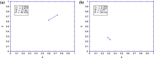
For the analysed problems, it was assumed that only the extended displacement solution on the right side () was known. Twelve measurement points have been considered. The applied load considered is a unitary uniformly distributed mechanic load, as depicted in Figure .
As stated previously, a dual BEM has been implemented to numerically solve the direct problem. The external boundary of the plate has been discretized with six quadratic elements per side. The crack boundary was discretized using 10 discontinuous quadratic elements, where the crack-tip elements are discontinuous quarter-point (see [Citation17, Citation28]).
Table 3 Crack identification of the reference cracks for SNNs.
Fig. 4 Damage identification with SNNs. Input: eletric and magnetic potentials .
NN parameters
The following NN parameters were selected through trial-and-error:
| 1. | Architecture: | ||||
| 2. | Training set: 1500 input/output entries | ||||
| 3. | Validation set: 1500 input/output entries; | ||||
| 4. | Training algorithm: Levenberg–Marquardt [Citation27]; | ||||
| 5. | Goal MSE: | ||||
| 6. | Maximum number of iterations: 100. | ||||
Fig. 5 Training set division.
The training set was selected among random possibilities to obtain a uniform distribution of the damage parameters. Early stopping [Citation29] was applied in every NN. The training set is composed of 1500 inputs, where 600 are used in training and 600 in the validation. The validation set has the purpose of inspectioning the evolution of the NN error for non-trained inputs. If the error of the validation set starts increasing, the NN training is interrupted to prevent overfitting. The remaining 300 inputs are used to evaluate the performance of the NN.
The NN were trained with three different types of inputs. For one case, only the electric potential was given as training information to the NN. Then, only the magnetic potential
was given as input. Finally, a combination of electric and magnetic potential has been used as NN input. If simple entries are used,
, otherwise
.
A validation error (VE) is defined as the distance between real and identified parameters like [Citation15](14) where
and
are the identified and real parameters, respectively. The NN output is the crack tip positions, defined by the parameters
,
,
and
. These parameters were taken in their normalized form as shown in Table , and the orientation parameter
was normalized dividing its value in degrees by 180.
Additionally, a variable was introduced to verify the quality of the identification provided by the NN, defined as
(15) where
and
are the coordinates of the crack tips predicted by the NN and
y
are the actual coordinates of the crack tips.
Fig. 6 NN training parameters.
The influence of noise was also considered. At the present work, pseudo-experimental inputs were created by adding noise to the numerical results [Citation15] as stated in Equation (16)(16) where
is the amount of noise, varying from
to
.
is a random variable with mean
and standard deviation
. The root mean square is used as an estimation of the differences that are noted from the predicted values
to the real observation
. The NN input is the distortion caused by the presence of the damage in the plate and is defined as
(17) where
and
are the extended displacement solution, i.e. the electric potential, the magnetic potential, or a combination of both, for a damaged and undamaged plate, respectively.
Two crack configurations were employed to check the accuracy of the different damage identification approaches, as depicted in Figure .
Damage identification with standard neural networks (SNNs)
As an initial approach, the use of a SNN will be considered for the identification of different types of cracks. Table contains the identification results for different inputs and noise levels for the reference cracks.
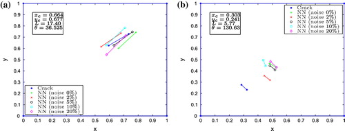
Fig. 7 Damage identification for partitioned training set. Input: eletric and magnetic potentials .
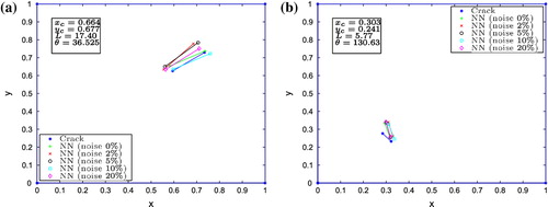
Table 4 Detail of the crack identification of the reference cracks. Input: eletric and magnetic potentials . Noiseless case.
Table 5 NN crack identification of the reference cracks. TSD.
To illustrate these results, Figures shows the identification calculated by the NN for different levels of noise and applying the electric and magnetic potentials as inputs of the standard NN. The large crack is identified with reasonable precision for all applied noise levels (Figure ). However, the NN provides a bad identification for the small crack (Figure ).
Training set division
The SNN is not able to perform an accurate identification for small crack patterns. In this work, the position of the identified small crack given by the SNN is always close to the central area of the plate. One possible explanation of this fact is that the SNN cannot reduce the error for this pattern without sacrificing the generalization capability of the NN (early stopping), since a small crack represents just a small distortion of the response at the boundaries.
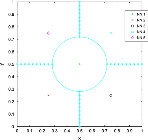
The solution considered to overcome this limitation was to divide the training set. This approach was successfully implemented by Benders et al. [Citation30] and Zhao [Citation31] for modular NN, which consist in a divide-and-conquer procedure. In this formulation, a complex task is separated in several sub-tasks, and a central integration machine is responsible for assembling the final solution. In our case, the training set has been divided into five regions: a central region defined by a circle of radius 1.75/8 plus four equally distributed regions as depicted in Figure . The central regions defined to better check the performance of the resulting TSD approach, once observed the tendency of the SNN to sistematically predict the position of the small cracks around the center of the plate. Subsequently, the patterns of each region were trained by individual NN. The parameter selected to uniquely define whether a particular crack belongs to one of these five regions is the crack center position.
The approach used in the present work is similar to the ones found in modular NN. However, in the present work, each NN has been trained with patterns for a specific region, therefore, it is only able to identify the cracks in its corresponding area. Each individual NN can provide a crack identification result; so, there is no need of a central integration machine to give the final crack identification.
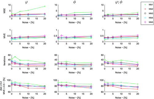
Figure presents the NN MSE, the mean validation error (MVE) over the trained NN, number of training iterations and the number of valid identification patterns according to the parameter and the MVE. The MVE shows a slow increase with the noise, which indicates the generalization capabilities of the NN are little affected by noise increments. However, one can observe the decay of precision with increase of noise levels. In all NN inputs, the number of reasonable identified patterns is located between
(for high noise levels) and
(no noise). Through evaluation of the identification of randomly chosen cracks, it was verified that reasonable identification results exhibit values up to 0.2 of the
parameter and MVE up to 0.5.
Figure illustrates the identification results of the reference cracks for the combined electric and magnetic potentials input.
Table shows the identification results of the reference cracks for every division and the noiseless case only. Non-reliable crack identification is obtained when evaluating an input that does not belong to the correct TSD. For the large crack identification, crack configurations outside the plate are found. For the small crack identification, only NN2 (the region where the real crack is placed in our example) predicts a crack center located inside its training space. Meanwhile, NN1, NN3, NN4 and NN5 predict a crack center position that, although inside the limits of the plate, is outside their respective training spaces, thus disproving the validity of the identification results. As expected, in all the numerical tests performed with TSD, there is only one NN that predicts the crack center position within the limits of its own training space.
Table contains the relevant information for the other NN input types. After adopting the TSD, the NN perform a good damage identification for all crack patterns and noise levels.
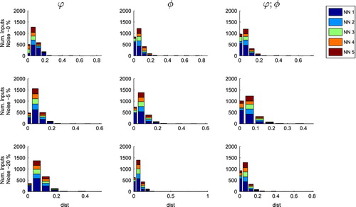
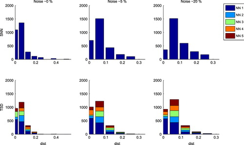
Figure details the pattern distribution for each NN in function of the parameter and considering the MVE lower than 0.5. The quality of the identification results is similar for NN 2 to NN 5, for all types of inputs. The larger presence of NN 1 is due to the difference in the number of elements, since this NN includes more training patterns that the others NN. Most of the analysed inputs have
, which does not denote a perfect identification but still represents a good approximation of the real crack, particularly when noise is present. Hence, it confirms that the applied TSD is a good method to improve the accuracy of the NN.
Fig. 8 parameter histograms with VE lower than 0.5. TSD. Input: eletric and magnetic potentials
.
Figures and compare the SNN and TSD in terms of the parameter, considering the combination of electric and magnetic potentials as inputs of the NN. From Figure , the SNN provides the best identification results when using the electric as only input of the NN. The correct identification rate is up to
for the noiseless cases, and decreases to
for high noise levels. However, considering the same input type, the identification results obtained with the TSD approach are noise insensitive, with minimal correct identification results of
for high noise levels, up to
when noise is disconsidered. From Figure , the distribution of the
parameter is similar for both methods when noise is zero. Nevertheless, the number of inputs where
is considerable higher with the TSD approach, specially for high noise level cases.
Fig. 9 parameter for several noise levels. Input: eletric and magnetic potentials
.
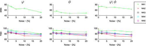
Fig. 10 parameter histograms for several noise levels. Input: eletric and magnetic potentials
.
Summary and conclusions
This work presents a new damage identification framework for MEE materials using an artificial intelligence tool. It is shown that SNN is not capable to identify all types of crack patterns correctly. To overcome this limitation, a division of the training set (TSD) was adopted, with each part being assigned to independent NN. This division was based in regions of the plate, using the fact that the SNN has the tendency to identify cracks in the central area of the plate. The identification results after the TSD have largely improved. In general, the NNs present good results in identifying a crack using only some partial information of the BEM solution. The input type affects the identification behaviour of the networks. Better results are achieved when using the combination of electric and magnetic potentials rather than any of these potentials alone, as it could be expected. The NN simulation may be used as a good estimation of the crack location in MEE materials.
Acknowledgments
This work was funded by the Ministerio de Ciencia e Innovación, Spain, research project DPI2010-21590-C02-02.
References
- Gao, C, Kessler, H, and Balke, H, 2003. Crack problems in magnetoelectroelastic solids. Part I: exact solution of a crack, Int. J. Eng. Sci. 41 (2003), pp. 969–981.
- Gao, C, Tong, P, and Zhang, T, 2004. Fracture mechanics for a mode III crack in a magnetoelectroelastic solid, Int. J. Solids Struct. 41 (2004), pp. 6613–6629.
- Jiang, X, and Pan, E, 2004. Exact solution for 2D polygonal inclusion problem in anisotropic magnetoelectroelastic full-, half-, and bimaterial-planes, Int. J. Solids Struct. 41 (2004), pp. 4361–4382.
- Wu, TL, and Huang, JH, 2000. Closed-form solutions for the magnetoelectric coupling coefficients in fibrous composites with piezoelectric and piezomagnetic phases, Int. J. Solids Struct. 37 (2000), pp. 2981–3009.
- Chue, CH, and Liu, TJC, 2005. Magnetoelectroelastic antiplane analysis of a bimaterial composite wedge with an interface crack, Theor. Appl. Fract. Mech. 44 (2005), pp. 275–296.
- Pan, E, 2001. Exact solution for simply supported and multilayered magneto-electro-elastic plates, J. Appl. Mech. ASME. 68 (2001), pp. 608–618.
- Rojas-Díaz, R, Sukumar, N, Sáez, A, and García-Sánchez, F, 2011. Fracture in magnetoelectroelastic materials using the extended finite element method, Int. J. Numer. Methods Eng. 88 (2011), pp. 1238–1259.
- Zhong, XC, and Li, XF, 2007. Magnetoelectroelastic analysis for an opening crack in a piezoelectromagnetic solid, Eur. J. Mech. 26 (2007), pp. 405–417.
- Tarantola A. Inverse problem theory and methods for model parameter estimation. Philadelphia (PA): 2nd Society for Industrial and Applied Mathematics; 2004..
- Islam, AS, and Craig, KS, 1994. Damage detection in composite structures using piezoelectric materials, Smart Mater. Struct. 3 (1994), pp. 318–328.
- Kubo S, Sakagami T, Suzuki T, Maeda T, Nakatani K. Use of the piezoelectric film for the determination of cracks and defects – the passive and active electric potential CT method. J. Phys: Conf. Ser. 2008;135:art. no. 012057..
- Su Z, Ye L. Identification of damage using lamb waves. London: Springer; 2009..
- Comino, L, Rus, G, and Gallego, R, 2008. Combining topological sensitivity and genetic algorithms for identification of inverse problems in anisotropic materials, Comput. Mech. 41 (2008), pp. 231–242.
- Lu, Y, Ye, L, Su, Z, Zhou, L, and Cheng, L, 2009. Artificial Neural Network (ANN)-based crack identification in aluminium plates with Lamb wave signals, J. Intell. Mater. Syst. Struct. 20 (2009), pp. 39–49.
- Rus, G, Palma, R, and Pérez-Aparicio, JL, 2009. Optimal measurement setup for damage detection in piezoelectric plates, Int. J. Eng. Sci. 47 (2009), pp. 554–572.
- Palma, R, Rus, G, and Gallego, R, 2009. Probabilistic inverse problem and system uncertainties for damage detection in piezoelectrics, Mech. Mater. 41 (2009), pp. 1000–1016.
- García-Sánchez, F, Rojas-Díaz, R, Sáez, A, and Zhang, C, 2007. Fracture of magnetoelectroelastic composite materials using boundary element method (BEM), Theor. Appl. Fract. Mech. 47 (2007), pp. 192–204.
- Haykin S. Neural networks – a comprehensive foundation. 2nd ed. Upper Saddle River (NJ): Prentice Hall; 1999..
- Barnett, D, and Lothe, J, 1975. Dislocations and line charges in anisotropic piezoelectric insulators, Phys. Stat. Sol. 76 (1975), pp. 105–111.
- Soh, A, and Liu, J, 2005. On the constitutive equations of magnetoelectroelastic solids, J. Intell. Mater. Syst. Struct. 16 (2005), pp. 597–602.
- Aliabadi, MH, 1997. Boundary element formulations in fracture mechanics, Appl. Mech. Rev. 50 (1997), pp. 83–96.
- Liu YJ, Mukherjee S, Nishimura N, Schanz M, Ye W, Sutradhar A, Pan E, Dumont NA, Frangi A, Saez A. Recent advances and emerging applications of the boundary element method. Appl. Mech. Rev. 2011;64:p. art. no. 031001..
- Ramm AG. Inverse problem: mathematical and analytical techniques with applications to engineering. New York: Springer; 2005..
- Waszczyszyn, Z, and Ziemiański, L, 2001. Neural networks in mechanics of structures and materials – new results and prospects of applications, Comput. Struct. 79 (2001), pp. 2261–2276.
- Xiu, YG, Liu, GR, Wu, ZP, and Huang, XM, 2001. Adaptive multilayer perceptron networks for detection of cracks in anisotropic laminated plates, Int. J. Solids Struct. 38 (2001), pp. 5625–5645.
- Araújo, AL, Soares, CMM, Herskovits, J, and Pedersen, P, 2006. Parameter estimation in active plate structures using gradient optimisation and neural networks, Inverse Prob. Sci. Eng. 14 (2006), pp. 483–493.
- Hagan MT, Demuth HB, Beale M. Neural networks design. Boston (MA): PWS; 1996..
- Sáez, A, Gallego, R, and Domínguez, J, 1995. Hypersingular quarter-point boundary elements for crack problems, Int. J. Numer. Methods Eng. 38 (1995), pp. 1681–1701.
- Prechelt, L, 1998. Automatic early stopping using cross validation: quantifying the criteria, Neural Networks 11 (1998), pp. 761–767.
- Bender T, Gordon VS, Daniels M. Partitioning strategies for modular neural networks. In: Proceedings of International Joint Conference on Neural Networks; Atlanta (GA): 2008. p. 296–301..
- Zhao, ZQ, 2009. A novel modular neural network for imbalanced classification problems, Pattern Recognit. Lett. 30 (2009), pp. 783–788.