 ?Mathematical formulae have been encoded as MathML and are displayed in this HTML version using MathJax in order to improve their display. Uncheck the box to turn MathJax off. This feature requires Javascript. Click on a formula to zoom.
Abstract
In this paper, a two-step free-form shape optimization methodology is presented for designing the optimal shapes of shell structures concerning stiffness maximization problem subject to a volume constraint. With this methodology, the optimization design problem of a shell structure is divided into two steps which consist a surface optimization step and a boundary optimization step. The shape sensitivities, called shape gradient function, are theoretically derived for both steps using the Lagrange multiplier method and the formula of the material derivative. The optimal shape is determined by applying the derived each shape gradient function on a design surface or boundaries to the gradient method. By the two-step free-form optimization, a smooth optimal shell with free-form surface and boundaries can be obtained to be a weight reduced form with high stiffness. Several calculated examples are presented to verify the validity and practical utility of the proposed methodology.
Introduction
In shape optimization of the free-form shell structures, the geometrical representation can be based on parametric method and parameter-free method (or node-based method).[Citation1]
The parametric method needs shape parametrization in advance, and basis vectors and parametric surface such as Bezier surface and non-uniform rational B-spline (NURBS) are often used for the description of free-form shells.[Citation2] This method is effective to the reduction of the design variables and most of the optimization methods proposed in previous studies are parametric methods.[Citation3–Citation7] However, the parametrization needs knowledge and experience, and with complication of the forms, parameter selection is troublesome for the designers. Moreover, the obtained shape by the parametric method is strongly influenced by the selected parameters, especially for the basis vector method.
In the node-based method, nodal coordinates are taken as design variables. Due to the result is not restricted to the parametrization, this method gives more freedom to the optimization process and the obtained optimal shape is near a result of natural choice. The node-based method has needed to overcome problems such as the large number of design variables and the jagged boundaries which were pointed out in one of the earliest works on shape optimization by Braibant and Fleury [Citation8]. Bletzinger et al. used the adjoint variable method in the sensitivity analysis to solve the large-scale design variables problem, and the use of minimal surface and filtering technique has been proposed as a solution to the jagged boundary problem.[Citation9] Scherer et al. proposed a fictitious energy approach to constrain the shape change as a new regularization technique.[Citation10] Shimoda et al. have previously proposed a parameter-free optimization method for free-form shells based on the traction method, which is a type of gradient method in a Hilbert space.[Citation11]
In this method, the adjoint variable method is also employed and the use of force for varying the surface reduces the objective functional while maintaining boundary smoothness.[Citation12–Citation14] In the shape optimization of the free-form shells performed by Shimoda et al., two kinds of shape variations was considered as design variables. One is out-of-plane shape variation, which varies the shape of a shell in the normal direction to the surface. The optimal surface shape can be obtained by optimization of the out-of-plane shape variation. Comparing to the initial shape, the optimized surface shape can substantially improve the structural characteristics.[Citation12, Citation13] The other is in-plane shape variation, which changes a shell in the tangential direction to the surface. The optimal boundary shape can be obtained by optimizing the in-plane shape variation while maintaining the curvature distribution of the surface. The boundary shape optimization is effective to determine the detailed form of a shell, to find a weight saving form and to improve the structural characteristics, especially when performed in the final designing stage.[Citation14]
For designing free-form shells with both light weight and high mechanical performance, this paper presents a new shape optimization methodology for designing optimal surface and boundary shapes of shell structures by combining the out-of-plane and in-plane free-form optimization method with two-step, which is a parameter-free method without any shape parametrization. In the first step, a shape is varied in the normal direction to the surface in order to determine the optimal curvature distribution. In the second step, the optimal boundary shape is determined while maintaining the optimal curvature distribution of the surface determined in the first step. As an application of this methodology, the mean compliance minimization problem of shell structures is dealt with in this paper. The problem is formulated as a distributed-parameter shape optimization problem, and a shape sensitivity, called a shape gradient function, is theoretically derived for both steps using the Lagrange multiplier method and the formula of the material derivative. Each shape gradient function on a design surface or boundaries is used as a distributed external force in each step to determine the optimal shape, which is the gradient method modified by one of the authors for shell design problem from the original one.[Citation12–Citation14] With this approach, the jagged-shape problem [Citation8] caused by parameter-free method is resolved, and a smooth optimal shell with free-form surface and boundaries can be obtained. Several calculated examples are presented to demonstrate the effectiveness and practical utility of the proposed methodology.
Modelling and governing equation of shell structure
As shown in Figure and Equations (1)–(3), consider a shell having an initial bounded domain ( boundary of
), mid-area
(boundary of
), side surface
and plate thickness
. It is assumed for simplicity that a shell structure occupying a bounded domain is a set of piecewise flat surfaces as shown in Figure .
As shown in Figure , forces acting relative to the local coordinate system on the domain
and the boundary
are defined as follows: an out-of-plane load
per unit area, an in-plane load
, and an out-of-plane moment
per unit area, an in-plane load
per unit length, a shearing force
per unit length and a bending moment
per unit length.
(7)
(7) where
expresses a variation. In addition, the bilinear form
and the linear form
are defined respectively in Equations (8) and (9).
(8)
(8) where
and
express an elastic tensor including bending and membrane components, and an elastic tensor with respect to the shearing component, respectively.
,
and
express an elastic tensor with respect to bending, shearing and membrane stress, respectively. In addition,
and
, respectively express the curvatures and the transverse shear strains which are defined by the following equations. The constant
denotes a shear correction factor, which is used as
in the Reissner theory.[Citation16]
(9)
(9)
(10)
(10) It will be noted that
in Equation (7) is given by the following equation.
(11)
(11) where
is the Sobolev space of order 1.
Surface and boundary optimization problem of shell
Domain variation
The shape variation directions that determine the shape of a shell structure can be classified as out-of-plane variation in the normal direction to the surface and in-plane variation in the tangential direction to the surface as shown in Figure . Consider that a linear elastic shell structure having an initial domain , mid-area
, boundary
and side surface
undergoes domain variation
(design velocity field) in the out-of-plane direction and/or in the in-plane direction such that its domain, mid-area, boundary and side surface become
and
, respectively. It is assumed that the plate thickness
remains constant under the domain variation. The domain variation at this time can be expressed by a mapping from
to
, which is denoted as
(
is a small integer) given by
.[Citation17] The subscript s expresses the iteration history of the domain variation. Assuming a shape constraint is acting on the variation in the domain, the infinitesimal variation of the domain can be expressed by
Compliance minimization problem
Let us consider a free-form optimization problem for maximizing the stiffness of a shell structure. Letting the state equation in Equation (7) and the volume be the constraint conditions and the compliance be the objective functional to be minimized, a distributed-parameter shape optimization problem for finding the optimal design velocity field , or
can be formulated as shown below:
(13)
(13)
(14)
(14)
(15)
(15)
(16)
(16) where
and
denote the volume and its constraint value, respectively. Letting
and
denote the Lagrange multipliers for the state equation and volume constraints, respectively, the Lagrange functional
associated with this problem can be expressed as
(17)
(17) For the sake of simplicity, it is assumed that the sub-boundaries acted on by the non-zero external forces
,
and
do not vary (i.e.
) that the forces acting on the shell surface
and
do not vary with regard to the space and the iteration history
(i.e.
). Then, the material derivative
of the Lagrange functional can be derived as shown in Equation (19) below using the formula of material derivative.[Citation17]
(18)
(18) where,
(19)
(19) As shown in Figure , the notation
in Equation (20) is defined as an out-of-plane outward unit normal vector (i.e. in the normal direction to the surface) on the surface
for the out-of-plane shape variation, and the relationship
for the out-of-plane shape variation is assumed by using the notations
and
, unit normal vectors that make the outward top and bottom surfaces of the shell positive. The notation
in Equation (21), as shown in Figure , is defined as an in-plane outward unit normal vector (i.e. in the tangential direction to the surface:
) on the boundary
for the in-plane shape variation. The notation
denotes twice the mean curvature of the surface. Additionally,
expresses the admissible function space that satisfies the constraints of domain variation. The notation
and
are the shape derivative and the material derivative with respect to the domain variation, respectively.[Citation17]
When the optimality conditions with respect to the state variable , the adjoint variable
and
are satisfied, Equation (19) becomes
(20)
(20) The shape gradient functions, which are the sensitivity functions used to determine the optimal shape, are calculated in Equations (23) and (24) by considering the self-adjoint relationship
.
Free-form optimization method for obtaining optimal surface and boundary of shell structures
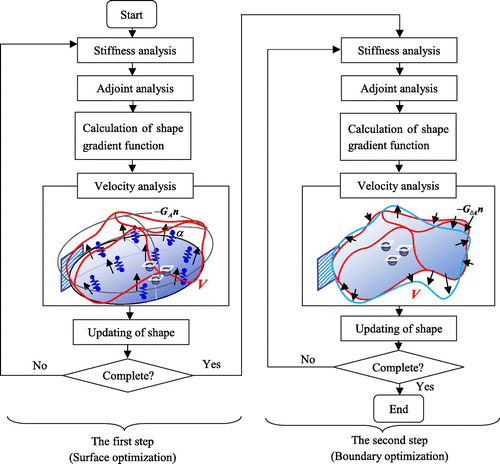
The free-form optimization method described here is based on the traction method (or the gradient method,[Citation11]) which is a gradient method in a Hilbert space. The original traction method was proposed by Azegami in 1994.[Citation18, Citation19] We have been modifying the original method for shell optimization.[Citation12–Citation14] It is a node-based shape optimization method that can treat all nodes as design variables and does not require any design variable parametrization. This approach makes it possible to obtain the optimal free-form surface and boundary shapes of shell structures. As shown in Figure , the Robin boundary conditions (spring constant
) [Citation20] are defined in the case of surface optimization, while the Dirichlet conditions (as shown in Figure ) or the Robin conditions are defined for a pseudo-elastic shell in the case of boundary optimization with this method. In the case of surface optimization, a distributed force proportional to the shape gradient function
is applied in the normal direction to the surface and a distributed force proportional to the shape gradient function
is applied in the tangential direction to the surface in the case of boundary optimization. The analysis for shape variation is called a velocity analysis. The shape gradient function is not applied directly to the shape variation but rather is replaced by a force. This makes it possible both to reduce the objective functional and to maintain the smoothness, i.e. mesh regularity, which is the most distinctive feature of this method.
Considering the design velocity as a combination of the in-plane velocity
and the out-of-plane velocity
, the governing equation of the velocity analysis for
in the boundary optimization with the Dirichlet conditions is expressed as Equation (25). Moreover, when the free boundary shape is found using Equation (25), an additional constraint is put on variation in the normal direction, as it is assumed that the initial curvature of the shell surface will be maintained.
(21)
(21) where
is expressed as
(22)
(22) The governing equation of the velocity analysis for the surface optimization with the Robin conditions is expressed as Equation (27).
The general process by this two-step optimization methodology is schematized in Figure . In each step, firstly, the stiffness analysis and the adjoint analysis (not necessary in this study) were done by a standard commercial FEM code and outputs of the analyses were utilized to calculate the shape gradient function. After that, a distributed force proportional to the shape gradient function or
was applied to determine the design velocity field
of each iteration, and the shape is updated iteratively using the design velocity field
. This process was repeated until the optimal shape of each step was obtained.
By this process, the optimal surface shape was determined to enhance the stiffness in the first step, and the boundary shape optimization was performed subsequently in the second step, which contributes to reduce the part of low load transmission to achieve a minimum weight. Then, a weight reduced form with high stiffness can be obtained.
Results of numerical calculation
In order to confirm the validity and practical utility of the developed two-step optimization methodology for designing the optimal free-form of shell structures, square plate, shaped bracket and spherical shell design problem were given below as fundamental design examples. In each design example, the linear static analysis was performed by the MSC NASTRAN finite element code, in which linear triangular shell elements with one integration point through the element thickness were employed to describe more detailed and smooth surface shapes of shells. Moreover, the element quality in the mesh of the model was inspected by the MSC Nastran throughout the optimization process, which will be discontinued when severely distorted element is found.
In all design problems, the volume constraint of the first step was set as of the initial shape and that of the second step was set as
of the optimized shape by the first step, the earth spring constant
, which was equivalent to
(
: bending rigidity).[Citation13]
Square-plate design problem
A stiffness design problem of a square plate under torsion was considered as the first application example of the two-step free-form optimization methodology. Initial shape and boundary conditions of the stiffness analysis for this problem are shown in Figure . The ‘SPC’ in Figure expresses the single-point constraint, and 1, 2 and 3 express the and
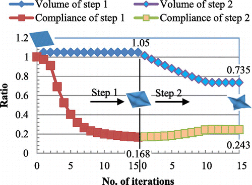
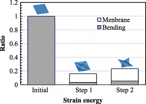
translational degrees of freedom, respectively. The constraint conditions of the velocity analysis in the first and second steps are shown in Figure respectively. The constraint conditions of the velocity analysis can be freely defined according to the practical design requirements. But, in accordance with the assumption in the derivation of the shape gradient functions as mentioned in Section 3.2, the loading and constraint points in the stiffness analysis were constrained in each step of the velocity analysis. Moreover, all boundaries were pin-constrained (SPC:123) in the first step to maintain the basic outline of the initial shape. Figure shows the initial shape and Figure shows the optimized shape obtained by the first step and the second step respectively. Iteration convergence of the compliance and the volume are shown in Figure and the values were normalized to those of the initial form. To investigate variation of the load-carrying performance of membrane and bending, a comparison of the ratio of strain energy is made between the initial form and the optimal forms obtained by each step, and the result is shown in Figure , where the values are normalized to the total strain energy of the initial form.
As a result of the surface optimization performed in the first step, the optimal curvature distribution shown in Figure was obtained and an X-type bead was created on the surface of the plate. Accordingly, the compliance was approximately decreased from the value of the twisted plate with the initial shape while satisfying the given volume constraint. It means that stiffness of the square plate under torsion was substantially increased by the obtained optimal curvature distribution. In the comparison result of the ratio of the strain energy shown in Figure , the strain energy of the initial form was completely dominated by the bending component, and that of the plate with the optimal surface was almost dominated by the membrane component as being expected, while the total strain energy was reduced substantially.
Then, by the boundary optimization performed in the second step, the optimal boundary shape was determined while maintaining the optimal curvature distribution of the surface determined in the first step. As shown in Figure , large shape variation occurred for obtaining the sufficient load path from the clamped four corners to the load points. In spite of large reduction of the volume (from to
), the compliance increased only about
. After surface and boundary shape was optimized in stages by the first and the second steps, the compliance of the twisted plate was decreased by about
from the initial shape, while the volume was decreased by
. It is obvious that both stiffened and lightweight forms can be obtained simultaneously by the two-step free-form optimization methodology.
L-shaped bracket design problem
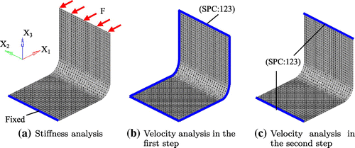
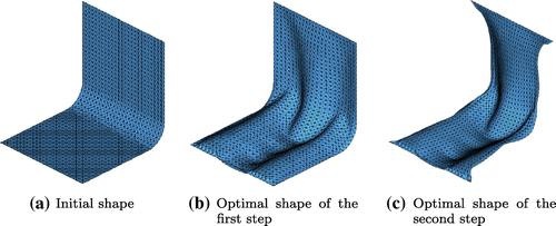
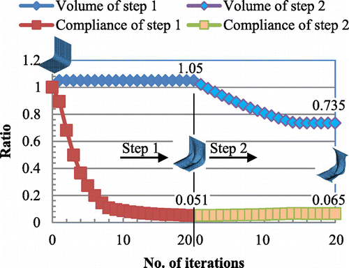
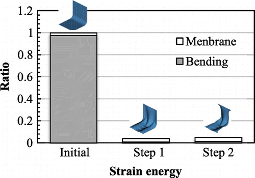
A shaped bracket under bending, as shown in Figure , was optimized as the second application example by the optimization methodology. The boundary condition of the stiffness analysis is shown in Figure . In the stiffness analysis, a uniformly distributed force was applied to the upper edge and the lower edge was fixed completely. The constraint conditions for the velocity analysis are shown in Figure , in which all boundaries were pin-supported in the first step and the two edges were pin-supported in the second step. Figure shows (a) the initial shape, (b) optimized shape obtained from the first optimization step and (c) final optimized shape by the two-step optimization. The iteration convergence histories of the compliance and the volume in each step are shown in Figure and the comparison of the ratio of strain energy between the initial form and the two optimal forms is shown in Figure .
By the surface optimization performed in the first step, the optimal curvature distribution shown in Figure was obtained and the compliance, as shown in Figure , was reduced by approximately while satisfying the given volume constraint (
of the initial form). With respect to the ratio of bending and membrane strain energy components, it is clear from Figure that the strain energy of the initial form was dominated almost entirely by the bending component and that of the form with optimized surface was almost dominated by the bending component, while the total strain energy was reduced drastically. Subsequently to the first step, the boundary optimization was performed in the second step and the optimal boundary shape shown in Figure was determined, while maintaining the optimal curvature distribution of the surface determined in the first step. As shown in Figure , the compliance increased slightly around
in the second step, while the volume decreased drastically from
to
. Due to the two-step optimization, not only the compliance of the
shaped bracket with final optimal form was decreased by
, but the volume decreased by
from the initial form.
Spherical shell design problem
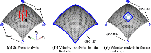
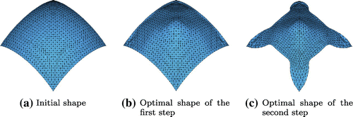
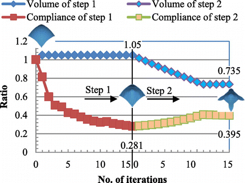
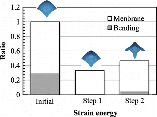
The third application example is a spherical shell design problem. Figure shows the boundary conditions of stiffness analysis, in which a uniformly distributed force was applied to the centre of the spherical shell and the four support points were fixed . The constraint conditions for the velocity analysis are shown in Figure . All boundaries were pin-supported in the first step, and the four support points and the loading points were pin-supported in the second step. Figure shows (a) the initial shape, (b) optimized shape obtained from the first optimization step and (c) final optimized shape by the two-step optimization. The iteration convergence histories of the compliance and the volume in each step are shown in Figure and the comparison of the ratio of strain energy between the initial form and the two optimal forms is shown in Figure .
As shown in Figure , smooth optimal surface and boundaries were obtained by the optimization methodology. It was confirmed that, as shown in Figure , the compliance of the final shape was about 72 decreased while the volume
decreased, and as shown in Figure , the strain energy of the final form was almost dominated by the membrane component.
Conclusions
In this paper, we have proposed the two-step free-form shape optimization methodology for designing the optimal shapes of shell structures with the aiming of stiffness maximization subject to volume constraints. In this methodology, the optimization design problem of a shell structure was divided into two steps, which are a surface optimization step and a boundary optimization step. The shape sensitivity, called shape gradient function, was theoretically derived for both steps using the Lagrange multiplier method and the formula of the material derivative. The optimal shape was determined by applying the derived each shape gradient function on a design surface or boundaries to the gradient method. It was confirmed by foundational and practical examples that, by the two-step free-form optimization methodology, a smooth optimal shell with free-form surface and boundaries can be easily obtained and the obtained final optimal shapes were not only weight reduced but also high stiffness. In addition to the stiffness design problem, the strength, vibration, buckling and their combined design problems will be considered in the future work.
Acknowledgments
This research was supported by grants-in-aid from the DAIKO FOUNDATION in Nagoya, Japan.
References
- Arnout S, Firl M, Bletzinger KU. Parameter free shape and thickness optimisation considering stress response. Struct. Multidisc. Optim. 2012;45:801–814.
- Fujita S, Ohsaki M. Shape optimization of shells considering quantity of local geometric characteristics. In: 6th China-Japan-Korea Joint Symposium on Optimization of Structural and Mechanical Systems; 2010 Jun 22–25; Kyoto, Japan; 2010.
- Ramm E, Bletzinger K-U, Reitiger R. Shape optimization of shell structures. Int. J. Shell Spatial Struct. 1993;34:103–121.
- Rao V, Hinton E. Analysis and optimization of prismatic plate and shell structures with curved planform. Shape Optim. Comput. Struct. 1994;52:341–351.
- Uysal M, Gul R, Uzman U. Optimum shape design of shell structures. Eng. Struct. 2007;29:80–87.
- Espath LFR, Linn RV, Awruch AM. Shape optimization of shell structures based on NURBS description using automatic differentiation. Int. J. Numer. Methods Eng. 2011;88:613–636.
- Liu M, Xing M, Yang Q, Yang X. Computational morphogenesis of free form shell structures by optimization. Procedia Eng. 2012;31:608–612.
- Braibant V, Fleury C. Shape optimal design using B-splines. Comput. Methods Appl. Mech. Eng. 1984;44:247–267.
- Bletzinger KU, Firl M, Linhard J, Wuchner R. Computational morphogenesis of free form shells: filter methods to create alternative solutions. In Proceedings of the IASS Symposium 2009; Valencia; 2009.
- Scherer M, Denzer R, Steinmann P. A fictitious energy approach for shape optimization. Int. J. Numer. Meth. Eng. 2010;82:269–302.
- Azegami H, Fukumoto S, Aoyama T. Shape optimization of continua using NURBS as basis functions. Struct. Multidisc. Optim. 2013;47:247–258.
- Shimoda M, Iwasa K, Azegami H. A shape optimization method for the optimal free-form design of shell structures. In: Proceedings of 8th World Congress on Structural and Multidisciplinary Optimization; Lisbon; 2009.
- Shimoda M. Free-form optimization method for designing automotive shell structures. SAE Int. J. Passenger Cars - Electron. Electr. Syst. 2011;4:42–54.
- Shimoda M, Tsuji J. Non-parametric shape optimization method for rigidity design of automotive sheet metal structures. SAE J. Passenger Cars - Mech. Syst. 2007;2006–01–0584:483–492.
- Reddy JN. Theory and analysis of elastic plates. Philadelphia (PA): Taylor and Francis; 1999.
- Reisser E. The effect of transverse shear deformation on the bending of elastic plates. J. Appl. Mech. 1945;67:A-69–A-77.
- Choi KK, Kim NH. Structural sensitivity analysis and optimization. New York : Springer; 2005.
- Azegami H. A solution to domain optimization problems. Trans. Jpn. Soc. Mech. Eng. Ser. A. 1994;60:1479–1486.
- Azegami H, Kaizu S, Shimoda M, Katamine E. Irregularity of shape optimization problems and an improvement technique. Comput. Aided Optimum Des. Struct. V. 1997:309–326.
- Azegami H, Takeuchi K. A smoothing method for shape optimization: traction method using the robin condition. Int. J. Comput. Methods. 2006;3:21–33.


