 ?Mathematical formulae have been encoded as MathML and are displayed in this HTML version using MathJax in order to improve their display. Uncheck the box to turn MathJax off. This feature requires Javascript. Click on a formula to zoom.
Abstract
Development of efficient model-updating and parameter estimation techniques is of great importance for civil structures. The present paper extends a recently developed cross-model cross-mode (CMCM) method for model updating and parameter estimation, when connectivity flexibility and boundary conditions are incorporated. First, the stiffness matrix of a beam member with semi-rigid joints at both ends is formulated, where the semi-rigid joints enable connections to be modelled as partially restrained. Second, boundary substructure elements are used to capture the stiffness and mass properties of the foundation. Finally, the model updating and parameter estimation of connection flexibility and boundary conditions are incorporated into the CMCM method. To validate the capability and effectiveness of the developed algorithm, numerical studies are conducted on a 2D bridge structure based on data generated from finite-element models. Numerical results demonstrate that the present method is effective for model updating and parameter estimation, when incorporating connectivity flexibility and boundary conditions.
Introduction
Accurate mathematical models are commonly required in modern analysis of structural dynamics. These accurate models are used in many applications of civil engineering structures like response prediction, damage detection, health monitoring and structural vibration control. A typical way to establish a mathematical model for a civil structure or mechanical system is via the use of the finite element method. The finite-element model (FEM) of a structure is constructed on the basis of highly idealized engineering blueprints and designs that may or may not truly represent all the physical aspects of an actual structure.[Citation1] Structural modelling errors cannot be completely avoided in any analytical procedure that relies on FEMs; these errors originate from many aspects such as simplified materials, inaccurate boundary conditions, as well as highly idealized connection joints.
In the field of civil engineering, beam-to-column connections play an important role in dynamic and stability analysis of frame structures,[Citation2, Citation3] where FEMs usually do not model with sufficient accuracy. In modelling the connections, FEMs generally represent the connections as either fully fixed or idealized pinned in conventional analysis and design of steel frames. Although the adoption of such idealized joint behaviour simplifies the modelling process, it by no means represents the actual behaviour of the structure since most connections in current practice actually exhibit semi-rigid deformation behaviour.[Citation4, Citation5] That is to say, the joint stiffness is somewhere in between. Under such circumstances, errors may be present if this simplified model is used for further analysis such as response prediction and damage detection.
Complexity of foundation-structure interface is another source of modelling errors. In the field of soil-structure interaction (SSI), it is well recognized that SSI has an important effect on the dynamic response of the structures, particularly when the soil is soft.[Citation6] Including SSI will change the computed dynamic characteristics of the structure, such as vibration frequencies and mode shapes. In dealing with the analysis of soil-structure interaction, the general procedure is to apply idealized constraints or to make use of previous experience in modelling apparently similar boundaries. The result of this approach is that many FEMs fail to represent boundary stiffnesses to an acceptable accuracy and consequently errors are produced in finite-element predictions.[Citation7–Citation9]
Therefore, model updating is usually used to obtain an accurate model of the real structure when field dynamic measurements are available. Model updating is defined as the process of modifying the mass, stiffness and damping parameters of the mathematical model using data obtained from modal test such that the updated model more correctly describes the dynamic properties of the subject structure.
A number of model-updating methods have been proposed. In general, these methods can be classified into two major groups: direct matrix methods and indirect, physical property adjustment methods.[Citation10–Citation12] The former were based on computing changes made directly to the mass and stiffness matrices. Such changes may have succeeded in generating modified models which have properties close to those measured in the tests, but do not generally maintain structural connectivity and the corrections are not always physically meaningful. The physical property adjustment methods are generally iterative, which involve using the sensitivity of the parameters to update the model. Hence those methods are in many ways more acceptable in that the parameters which they adjust are much closer to physically realizable quantities.
Hu et al. [Citation13, Citation14] developed an innovative method, named as the cross-modelcross-mode (CMCM) model-updating method, for the simultaneous updating of the stiffness and mass matrices. The method is so named because it involves solving a set of linear simultaneous equations for the physically meaningful correction factors, in which each equation is formulated based on the product terms from two same/different modes associated with the mathematical and experimental models, respectively. The CMCM method has the advantages of both the aforementioned direct matrix methods and the indirect physical property adjustment methods. While it is a non-iterative method and therefore very cost-effective in computational time, it also has the advantage of preserving the initial model configuration and physical connectivity of the updated model. More recently, the CMCM method has been successfully used in model updating with boundary conditions.[Citation15]
Most of the published techniques on model updating have been limited to basic properties of the major superstructure elements. Some of them only considers the effect of either connectivity flexibility [Citation7, Citation16] or complexities of foundation-structure interface.[Citation15, Citation18] However, model-updating and parameter estimation methods simultaneously incorporating connectivity flexibility and foundation effect have been rarely reported. If the connectivity flexibility and boundary conditions are not modelled correctly, any further analysis will be inaccurate. Mottershead et al. [Citation19] applied a sensitivity method to update finite-element models of welded joints and the boundary condition of a cantilever plate, where the ‘rigid’ boundary is updated using the effective length of the elements closest to the joint. Sanayei et al. [Citation20] developed a modal stiffness-based error function for parameter estimation considering the connection stiffness and boundary conditions. In the method, the soil-substructure super-element (SSS) is introduced into the parameter estimation for capturing stiffness and mass properties of the foundation. Partially restrained frame element is used to simulate the connection stiffness. The performance of the proposed error function and its use with the two interface elements is evaluated in a 2D bridge example. However, only one-end semi-rigid joint of a frame element was considered and the measured modes did not take the measurement noise into account.
The primary objective of the present paper is to extend the CMCM method for model updating and parameter estimation by incorporating the connection flexibility and boundary conditions, as well as the super-structural members. To this end, the remainder of this paper is organized as follows. First, a beam member with semi-rigid (flexible) joints at both ends is introduced and the stiffness matrix is formulated. Next, the soil-structure super-element was described to consider the soil foundation effect. In Section 4, the CMCM method was extended for model updating and parameter estimation by incorporating connection stiffness and boundary conditions. Finally, the performance of the proposed method and its use is evaluated via a 2D bridge example.
Beam member with flexible joints
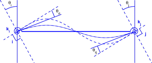
In traditional finite-element modelling, fully rigid or ideally pinned connections are often adopted for steel frames. However, the actual behaviour of the connections usually falls between this two extreme cases. Semi-rigid connections (flexible joints) enable connections to be modelled as partially restrained, which improves the quality of the model. Parameter estimation can be used to determine the joint stiffness of an in-service structure. To incorporate flexible joint(s), the effects of connection flexibility are modelled by attaching rotational springs at the two ends of a beam member, as shown in Figure , for a 2D frame element.
When a moment M is applied to a beam-column connection, the connected beam and column rotate relative to each other by an amount of . The relationship between end-moments and end-rotations of a beam can be written by replacing the end-rotations
and
by
and
respectively, after considering the vertical displacements of the ends, as follows [Citation21]:
(1a)
(1a)
(1b)
(1b) where L is the length of the beam member, I the moment of inertia, and E the Young’s modulus.
and
are the rotational stiffnesses of the spring connections at ends i and j, respectively.
and
are the relative rotations of the columns to the beam due to rotational connections at both ends,
and
, respectively.
and
are the shear displacements of the beam at ends i and j, respectively.
and
are the end moments of the beam at ends i and j, respectively. Equations (Equation1a
(1a)
(1a) ) and (Equation1b
(1b)
(1b) ) can be expressed in the following form:
(2a)
(2a)
(2b)
(2b) where
(3a)
(3a)
(3b)
(3b)
(3c)
(3c)
(3d)
(3d)
Following the process of forming stiffness matrix for a traditional rigid connection element, after considering the axial and shear loading, the stiffness matrix of a semi-rigid beam member with six degrees of freedom in local coordinates yields(4)
(4) where A is the cross-sectional area of the member. Applying the known steps of the matrix displacement method, this matrix is obtained in global coordinates for each member and structural stiffness matrix can be constituted.
Considering Equation (3), the stiffness matrix of Equation (Equation4(4)
(4) ) for
and
converges to the stiffness matrix corresponding to rigid connections at both ends. Similarly, Equation (Equation4
(4)
(4) ) leads to the stiffness matrix associated with pinned connections at both ends for
and
. Combinations (
,
) or (
,
) results in the stiffness matrix of an element with one end rigidly constrained and the other released. For
and/or
, the stiffness matrix is algebraically a non-linear function of
and/or
and I, which must be considered during a parameter estimation.
When and
, the stiffness matrix converges to the partially restrained frame (PRF) element described in Ref. [Citation20], as shown in Equation (Equation5
(5)
(5) ).
(5)
(5)
Soil-substructure super-element
Interaction between a structure at ground level, its foundation system and the underlying soil can be modelled with a detailed finite-element mesh. Such a detailed finite-element model has many parameters, and a large number of measurements are needed for successful parameter estimation. Traditionally, the interface stiffnesses are usually modelled by simple springs, where the lumped stiffnesses become the diagonal entries of the local stiffness matrix. This approach may oversimplify the model since it does not allow any coupling between the DoFs. The SSS can account for the coupling between DoFs that are typically neglected in practical analysis.[Citation20]
The SSS element models the complicated interfaces below the ground level of the structure. Since only the effect on the super-structure is relevant to the parameter estimation, the interaction of the foundation and the surrounding soil, as well as the overall behaviour of both deep and shallow foundations, is modelled in two dimensions by a matrix shown by in Equation (Equation6
(6)
(6) ).
(6)
(6) where the subscripts h, v and
denote the horizontal, vertical, and rotational coordinates, respectively. When a SSS element is under dynamic loading, it is not obvious how much of the surrounding soil engages with the vibration. The foundation geometry may also be unknown. Because of these difficulties, the masses for the SSS elements are also estimated.
Similar to that in Ref. [Citation20], the interface mass matrix, i.e. in Equation (Equation7
(7)
(7) ), is assumed to be a simple
diagonal matrix with diagonal elements
,
and
.
(7)
(7)
CMCM method incorporating flexible joints and boundary conditions
Recently, Hu et al. [Citation13] developed CMCM method for updating the structural properties associated with the super-structural elements in a finite-element model. In this section, the CMCM method is to be extended for model updating and parameter estimation, when structural connection flexibility and boundary conditions are incorporated.
In the development of the CMCM method, an initial model, characterized by the mass and stiffness
, is obtained from a finite-element model, with rigid connections and an initial guess of the boundary conditions. It is intended to ‘correct’ or ‘update’ the stiffness
and mass
matrices by measured modal parameters, including a few mode shapes and their corresponding frequencies, from the actual structure with flexible joints and actual boundary conditions.
In the original CMCM method, the stiffness matrix of the actual model is assumed to be
(8)
(8) where
is the stiffness matrix corresponding to the nth element and
the number of elements in the finite-element model.
are correction factors to be determined. Equation (8) means that the stiffness matrix
of the actual model is a modification of
obtained from a finite-element model. It should also be noted that only the properties of structural members will be modified and updated when
is written in Equation (Equation8
(8)
(8) ).
In the present paper, connection flexibility and boundary conditions will be incorporated into the CMCM method. Therefore, the stiffness matrix of the actual (experimental) model is assumed to be formulated as
(9)
(9) where
,
and
are the stiffness sub-matrices chosen for correction, which are corresponding to the structural elements, flexible joints and boundary conditions, respectively;
,
and
are total number of the chosen stiffness sub-matrices associated with structural elements, flexible joints and boundary conditions, respectively; and
,
and
are the corresponding correction coefficients to be estimated for the structural elements, flexible joints and boundary conditions, respectively. It should be noticed that the sub-matrix selection is very important since it is directly related to the correction coefficients for each submatrix. For example, if each element is assumed to involve a parameter to be updated, such as the Young modulus of each element,
will be the stiffness matrix corresponding to the nth element and
the number of elements in the finite-element model. How to select the sub-matrices and to determine the associated correction numbers will be illustrated in the numerical example.
Similarly, the mass matrix can be written as
(10)
(10) in which
and
are the mass sub-matrices associated with the structural elements and the boundary conditions, respectively, which is chosen for correction.
and
are the total numbers of mass sub-matrices to be corrected, corresponding to structural members and boundary conditions, respectively; and
and
are the corresponding correction coefficients to be estimated. It should be noticed that the flexible joints will not change the mass matrix when the corrected mass matrix is written in Equation (Equation10
(10)
(10) ).
Express the jth eigenvalue and eigenvector associated with and
as:
(11)
(11) where
and
, respectively, are the jth eigenvalue and eigenvector, associated with the actual structure, which are available from modal tests.
Premultiplying Equation (Equation11(11)
(11) ) by
yields
(12)
(12) Substituting Equations (Equation9
(9)
(9) ) and (Equation10
(10)
(10) ) into the above equation yields
(13)
(13) where
(14)
(14)
(15)
(15)
(16)
(16)
(17)
(17)
(18)
(18)
(19)
(19) and
(20)
(20) After using a new index m to replace ij, Equation (Equation13
(13)
(13) ) yields
(21)
(21) Rearranging Equation (Equation21
(21)
(21) ), one obtains
(22)
(22) or
(23)
(23) where
,
and
. When
reliable analytical modes are available from the finite-element model, and
modes are measured from the corresponding real structure, totally
CMCM equations can be formed from Equation (Equation23
(23)
(23) ). Written in a matrix form, one has
(24)
(24) or
(25)
(25) where
(26)
(26)
(27)
(27)
(28)
(28) and
(29)
(29) Noting that
and
are
-by-
and
-by-
matrices, respectively, where
and
.
and
are column vectors of size
and
, respectively; and
is a column vector of size
. Furthermore, one can rewrite Equation (Equation24
(24)
(24) ) as
(30)
(30) where
(31)
(31) and
(32)
(32) If
is greater than
, which means more equations are available than unknowns, one would expect that a least-squares solution for
can be taken
(33)
(33) From the above formulation of the CMCM method incorporating flexible joints and boundary conditions, one can see that it does not require the measured mode be paired with the same mode of the analytical model. Furthermore, the implementation of the CMCM method needs only the first few measured modes being arbitrarily scaled, i.e. normalization to the mass or to the unity is not necessary. It should also be noted that the complete mode shape is needed for implementing the current CMCM method and therefore the measured mode shapes should be expanded to estimate the values in unmeasured DoFs. And such expansion might affect the accuracy of the parameter estimation much more than the presence of noise in data.
Bridge example with flexible joints and boundary conditions
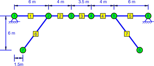
In this numerical example, the present CMCM method for model updating and parameters estimation will be illustrated and verified on a 2D bridge, as shown in Figure . The 2D bridge is similar to the type of bridge occasionally used for small river overpasses.[Citation20]
The total length of the bridge is 23.5 m. It consists of seven structural elements and 20 DoFs, where each member is modelled as a Euler-Bernoulli uniform beam element. In Figure , a circled number denotes a nodal point while a number with a square denotes an element. The density and elastic modulus of the material are kg/
and
N
m
, respectively. The element lengths are shown in Figure . Elements 1–5 are basic frame elements while elements 6 and 7, the legs of the bridge, both are elements with flexible joints, with the variable joint stiffness at nodes 2 and 5. At nodes 7 and 8, the base of the legs, boundary condition effect should be taken into account using the SSSs.
The values of the inertia moment and cross-sectional area are m
and
m
for the beam members, respectively, and
m
and
m
for the leg members, respectively. For the connection flexibility, since all the joints of the initial model were assumed to be of rigid connections, the initial connection stiffness of the flexible joints is not required. The initial values of the stiffness and mass matrices of foundation are listed in Table , which are chosen to to be identical to those used in Ref. [Citation20], except the initial parameters for
and
. These two initial parameters are zeros in Ref. [Citation20], but are set to be
in the present study. The reason is that one cannot update an zero initial value using CMCM method; and the correction coefficients will be
0.25 for these two parameters, which are identical to other stiffness correction coefficients, as listed in Table .
Table 1 Structural parameters for use in model-updating and parameter estimation.
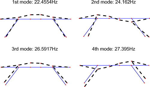
Finite-element model with initial structural properties, initial SSS and rigid connections is formulated as the baseline model. Modal analysis is carried out by developing a program in Matlab environment to get the FE frequencies and mode shapes. The first four vibration modes are shown in Figure . For a comparison, the modal frequencies of the first eight modes from the baseline model and the ‘measured’ correspondence from the simulated ‘actual’ structure and their Modal Assurance Criterion (MACs) are illustrated in Table .
Table 2 A comparison of the first eight modes of the FEM and simulated ‘measured’ case.
A similar damage scenario, as described in [Citation20], is presented in Table . This scenario is a representative of uniform deterioration of all bridge deck elements and leg elements. Note that the correction coefficients are defined as and the measured modal data are simulated based on the ‘actual’ values of the parameters.
For simulating an ‘actual’ structure with flexible joints and actual boundary conditions, it is assumed that elements 6 and 7 are connected with the deck by rotational springs at nodes 2 and 5. The stiffness of the connection springs at nodes 2 and 5 is both Nm/rad. At the same time, boundary conditions using the SSS elements are considered, where the ‘actual’ values are identical to those used in [Citation20]. Throughout this numerical example, the baseline model is defined as the finite-element model with rigid connections and initial boundary conditions. The ‘actual’ structure is defined as the finite-element model with flexible joints at the end of selected beam members and the true boundary conditions.
Parameters to be updated and estimated
In the present example, the inertia moment of all structural members, flexible joints at the leg-beam connections and the boundary conditions are to be updated while parameters such as cross-sectional area, elastic modulus, element length and mass density are considered to be constant. For a typical deterioration or damage observed in practice, reduction in bending rigidities is often observed. Therefore, the moment of inertia I of each structural member is to be estimated. As described in Section 4, if each element is assumed to involve a parameter to be updated, will be the stiffness matrix corresponding to the
th element and
the number of elements in the finite element model. Therefore, one needs seven correction coefficients for
with
, since there are 7 structural elements in the model.
For the semi-rigid joints updating, the initial model was assumed that all joints of the model are of rigid connections, with stiffness matrix for a Euler-Bernoulli uniform beam element in 2-dimension as follows.(34)
(34) When updating the semi-rigid joints, comparing Equation (Equation4
(4)
(4) ) with Equation (Equation34
(34)
(34) ), one can find that the connection stiffness changed the elements corresponding to the vertical and rotational DoFs (e.g.
,
and
related terms). Therefore, updating Equation (Equation34
(34)
(34) ) requires modification of these elements. One can select each individual
corresponding to one set of the connection stiffness. Denoting
as the counterpart of
in a
matrix form associated with the connection, one has the sub-matrices chosen as
In this way, the stiffness matrix of a beam member with semi-rigid connections at both ends can be written as
(35)
(35) Once the correction coefficient
is estimated, the connection stiffnesses,
and
at the left and right ends can be formulated as
(36)
(36)
(37)
(37) That is to say, there are three independent correction coefficients for a semi-rigid joints at both ends. When only one end, say the right end, has a semi-rigid joint, one can verify that only one correction coefficient is needed; and the correction coefficients yield
and
, if
is chosen as the one to be estimated. And the connection stiffness yields
(38)
(38) Hereby, one sets
for the present numerical example, since only nodes 2 and 5 of two bridge legs (members 7 and 8) have flexible joints.
For the stiffness and mass of the foundation, there are nine interface parameters intended to be estimated or updated, as listed in Table . By the same token, one can choose the sub-matrix for the SSS and set and
. Each individual
should correspond to one of the six interface stiffness coefficients. Likewise, each individual
is selected from one of the three interface mass coefficients. Totally, 27 parameters need to be estimated and updated for the bridge example.
From the above description, one can see that the present CMCM method for model updating and parameter estimation has the following merits: (1) In addition to the advantages of the traditional CMCM model updating methods, it can update finite-element model, incorporating flexible joints and boundary conditions; (2) In comparison with modal stiffness-based error function method, it has the advantage of updating flexible joints at both ends of a beam with different connection stiffness. At the same time, the initial connection stiffness is not required, since the initial model was assumed that all joints of the model are of rigid connections.
Task 1: model updating and parameter estimation with noise-free modal data
In principle, one needs to form 27 or more linearly independent CMCM equations in order to uniquely determine the 27 correction coefficients. Because the initial and target (true) models have the same form, and all measured modal parameters have been synthesized from the target model, zero prediction error for all coefficients is expected even when more than 27 CMCM equations are utilized. As stated before, when and
modes are taken from the initial and target models, respectively, there are
(=
) CMCM equations.
First, when all modes of the initial model () and only the first two modes of the target model (
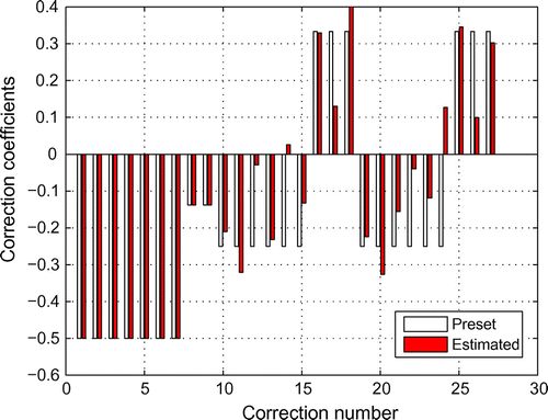
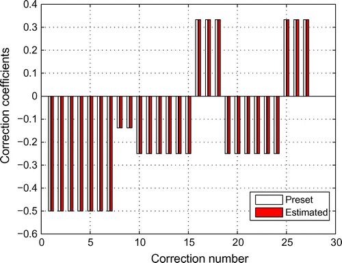
) are utilized to produce 40 CMCM equations, one finds that those CMCM equations form a rank deficient system. And the correction coefficients are shown in Figure . In Figure , the first seven correction coefficients are corresponding to bending rigidities of the structural members (
); correction numbers 8 and 9 are for semi-rigid joints (
for one end joint); and the last 18 factors are the interface correction coefficients for the two SSS of the boundary conditions (
and
for a single SSS). It could be seen from Figure that the estimated correction coefficients associated with the nine interface parameters are deviated with their preset values, while those corresponding to the structural members and semi-rigid joints are identical to the preset values. This rank deficiency may attribute to the fact that the measured first two modes are relevant to only some of the nine interface parameters. In other words, the measured first two modes can only access parts of the complete model space characterized by all parameters.
Next, taking the first three modes, i.e. and
, one finds that the solutions for all 27 coefficients are indeed identical to their true values, as illustrated in Figure . The correction coefficients associated with the semi-rigid joints are estimated to be
, for both the joints at nodes 2 and 5. The connection stiffness can be computed easily using Equation (Equation38
(38)
(38) ), which yields
Nm/rad, identical to the true values. This example demonstrates that the present CMCM method is numerically accurate and efficient under a mathematically ideal situation.
Task 2: model updating and parameter estimation with noise-polluted modal data
In practice, modal measurements always contain errors. Task 2 of this numerical study focuses on implementing the CMCM method when corrupted modes are measured. The value of the noise-polluted mode at each DoF will be generated based on multiplying its true value by a factor , where n is the noise level and
is generated based on a Gaussian distribution with zero mean and unit standard deviation. Maximum-normalized mode shapes are utilized for simulating the noise-polluted modal data. This is a common practice to simulate the noise effects, which has been adopted in many published papers.[Citation22, Citation23] It should also be noted that this kind of simulation is probably unrealistic when dealing with the real data. In fact, it seems too severe for DoFs where the modal deflections are quite high; on the other hand, when the mode shape is low, the signal-to-noise ratio is more unfavorable than modelled with
noise level. In addition, the lower values of mode shapes are expected corresponding to nodes of the structure, such as nodes 2 and 5 in Figure , where the joint flexibility has to be identified. Therefore, a more complex noise simulation method is preferred for this actual situation.
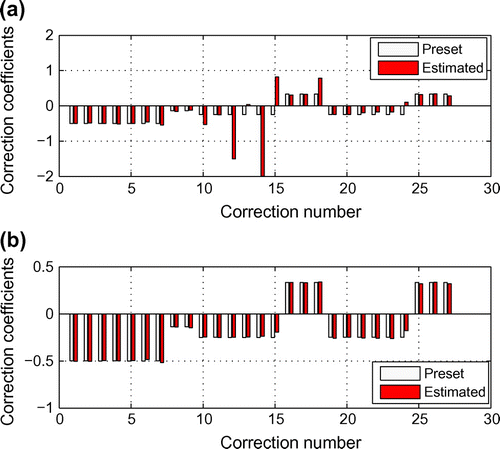
Fig. 6 Correction coefficients in task 2 under 0.5 noise level when using: (a) four modes and (b) six modes.
It is well known that Equation (Equation33(33)
(33) ) is a highly ill-posed problem. When the coefficient matrix is close to being rank deficient, then small levels of noise may lead to a large deviation in the estimated parameters from its ‘exact’ value. When enough modes are utilized under a relatively low level of noise, Equation (Equation33
(33)
(33) ) may yield acceptable results. Numerical simulation demonstrates that the identified parameters will yield acceptable results, when the first six modes are used under a 0.5
noise level. However, when fewer modes are utilized, the coefficient matrix is rank-deficient and the results are unacceptable. Shown in Figure is the estimated correction coefficients under a 0.5
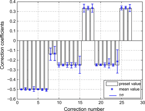
noise level, of which the top panel is from using four measured modes and the bottom panel from using six measured modes. As expected, employing more measured modes can often improve the reliability of the parameter estimation when modes contain random error. Note that Figure is the correction coefficients obtained from a single simulation. Undoubtedly, another simulation of the corrupted modes will yield different numerical results. To gain a statistical knowledge about the parameter estimation result, 1000 simulations were conducted. Figure shows the average and
range (
denotes the standard deviation) of the
from the 1000 simulations, where each simulation is based on a 0.5
noise level and six measured modes are employed in the CMCM method. From Figure , one can see that the mean correction coefficients agree perfectly well with their corresponding preset values. At the same time, the correction coefficients corresponding to correction numbers 24 and 15 possess larger
values, indicating that these two correction coefficients are most sensitive to measurement errors. Note that these two are corresponding to the rotational coordinates of the interface foundation.
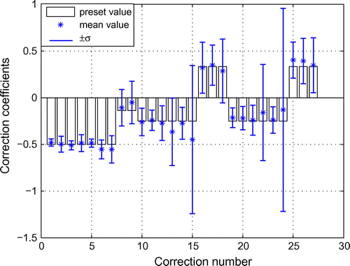
For investigating the robustness of the CMCM approach to severe noise, a 3 noise level is considered to simulate the measurement errors. The average and
range from the 1000 simulations is illustrated in Figure . As expected, a higher noise level indeed worsens the reliability of the model updating. From Figure , one can see that most of the mean values of the estimated correction coefficients still agree well with their preset values while a few of them deviate a bit larger from their counterparts, compared with those from a 0.5
noise level monte-carlo simulation. And more larger standard deviations (
) indicate a less robustness of these estimated correction coefficients against severe noise contamination. It should be noted that only the first six modes are included in the above simulation. If the first eight measured modes are utilized in the CMCM method, the reliability of the parameter estimation will be greatly improved. The results are not shown here, for space limitation.
Concluding remarks
The present paper extended a recently developed CMCM method for model updating and parameter estimation, when connectivity flexibility and boundary conditions were incorporated. The stiffness matrix of a beam member with semi-rigid joints at both ends was formulated, and the relationship between the correction coefficients and the connection stiffness was derived. SSSs were introduced to capture the stiffness and mass properties of the foundation. The model updating and parameter estimation of connectivity stiffness and boundary conditions were incorporated into the CMCM method. In addition to the updating of structural properties of each element, the present CMCM method was able to simultaneously update the flexible joints and boundary conditions in a finite-element model. Flexible joints at both ends of a beam with different connection stiffness could be considered. At the same time, the initial connection stiffness was not required to be known a priori. To validate the capability and effectiveness of the developed algorithm, numerical studies were conducted on a 2D bridge structure based on data generated from finite-element models. Two tasks were considered, in which different cases are investigated for each task. Numerical results demonstrated that the present method was effective for model updating and parameter estimation, when incorporating connectivity flexibility and boundary conditions.
The present CMCM method for structural model updating incorporating flexible joints and boundary conditions is a systematic approach, and theoretically, it is readily applicable to other kinds of structures. There are no particular numerical difficulties for 3D structures except that more correction coefficients are required to be updated.
Acknowledgments
The author would like to thank the two anonymous reviewers for their valuable comments, which greatly enhanced the quality of this paper. Also, the author acknowledges the financial support by the National Basic Research Program of China (2011CB013704), National Natural Science Foundation of China (50909088, 51010009) and Program for New Century Excellent Talents in University (NCET-10-0762).
References
- Bijaya J, Wei-Xin R. Structural finite element model updating using ambient vibration test results. J. Struct. Eng. 2005;131:617–628.
- Hadianfard MA, Razani R. Effects of semi-rigid behavior of connections in the reliability of steel frames. Struct. Saf. 2003;25:123–138.
- Bjorhovde R, Colson A, Brozzetti J. Classification system for beam-to column connections. J. Struct. Eng. 1990;116:3059–3077.
- Ihaddoudene ANT, Saidani M, Chemrouka M. Mechanical model for the analysis of steel frames with semi rigid joints. J. Constr. Steel Res. 2009;65:631–640.
- Turker T, Kartal ME, Bayraktar A, Muvafik M. Assessment of semi-rigid connections in steel structures by modal testing. J. Constr. Steel Res. 2009;65:1538–1547.
- Novak M. Effect of soil on structural response to wind and earthquakes. Earthquake Eng. Struct. Dyn. 1974;3:79C96.
- Wolf JP. Soil-structure-interaction analysis in time domain. Englewood Cliffs, NJ: Prentice-Hall; 1988.
- Stewart JP, Fenves GL, Seed RB. Seismic soil-structure interaction in buildings: Analytical methods. J. Geotech. Geoenviron. Eng., ASCE. 1999;125:26–37.
- Ahmadian H, Mottershead JE, Friswell MI. Boundary condition identification by solving characteristic equations. J. Sound Vibr. 2001;247:755–763.
- Ewins DJ. Modal testing: Theory, practice and application. 2nd ed. Research Studies Press; 2000.
- Mottershead JE, Friswell MI. Model updating in structural dynamics: A survey. J. Sound Vibr. 1993;167:347–376.
- Friswell MI, Mottershead JE. Finite element model updating in structural dynamics. Dordrecht: Kluwer Academic; 1995.
- Hu SLJ, Li HJ, Wang SQ. Cross-model cross-mode method for model updating. Mech. Syst. Signal Process. 2007;21:1690–1703.
- Hu SLJ, Li HJ. Simultaneous mass, damping, and stiffness updating for dynamic systems. AIAA J. 2007;45:2529–2537.
- Li YC, Li HJ, Hu SLJ, Chen XY, Gao ZQ. Boundary updating of offshore jacket structures based on measured modal frequencies. In: Proceedings of the Twenty-first (2011) International Offshore and Polar Engineering Conference; Cupertino, CA; 2011. p. 219–225.
- Nobari AS, Robb DA, Ewins DJ. A new approach to modal-based structural dynamic model updating and joint identification. Mech. Syst. Signal Proces. 1995;9:85–100.
- Law SS, Chan THT, Wu D. Super-element with semi-rigid joints in model updating. J. Sound Vibr. 2001;239:19–39.
- Nakhaei. M, Ali Ghannad M. The effect of soil-structure interaction on damage index of buildings. Eng. Struct. 2008;30:1491–1499.
- Mottershead JE, Friswell MI, Ng GHT, Brandon JA. Geometric parameters for finite element model updating of joints and constraints. Mech. Syst. Signal Process. 1996;10:171–182.
- Sanayei M, McClain JA, Wadia-Fascetti S, Santini EM. Parameter estimation incorporating modal data and boundary conditions. J. Struct. Eng. 1999;125:1048–1055.
- Chen WF, Lui EM. Stability design of steel frames. Boca Raton, FL: CRC Press; 1991.
- Sohn H, Law KH. A bayesian probabilistic approach for structure damage detection. Earthquake Eng. Struct. Dyn. 1997;26:1259–1281.
- Li H, Wang J, Hu S-LJ. Using incomplete modal data for damage detection in offshore jacket structures. Ocean Eng. 2008;35:1793–1799.

