 ?Mathematical formulae have been encoded as MathML and are displayed in this HTML version using MathJax in order to improve their display. Uncheck the box to turn MathJax off. This feature requires Javascript. Click on a formula to zoom.
Abstract
It is well established that the centrifuge can be an important tool to determine permeabilities of porous materials. Nevertheless, up to this date, for geotechnical applications, they are not used outside research laboratories. We attribute this to the cost of a centrifuge, the apparent requirement of measurements in the sample and the more complicated handling of samples for use in the centrifuge. As a first step towards an affordable centrifuge, we present an adaptation to a common bench-scale centrifuge, which allows to obtain measurements in a fraction of the time needed by standard infiltration methods, especially for clayey soils. The permeabilities are determined by measuring global transient data only: water level in an inflow or outflow chamber and gravitational centre of the sample or the rotational momentum of the sample. These are all measured outside of the centrifuge in a start-stop regime. A method of lines approach to solve the Richards’ equation is used, combined with interface tracking, which was previously shown to be an accurate method. Permeabilities are assumed to behave according to the van Genuchten–Mualem formula. We present the experimental set-up, accuracy of the measurements and the numerical solution method. For saturated flow, we compare with standard tests, while for unsaturated flow we compare with a pressure plate result (ASTM D2325). The results indicate the strengths and limitations of this approach, but overall we can conclude that measuring the global characteristics during rotation should provide accurate permeabilities.
Introduction
When predicting the performance of infiltration zones or clay covers, it is important to also determine the behaviour under unsaturated conditions. For example, compacted clay covers and linings of waste-management facilities are often in unsaturated conditions, and the same is true for infiltration zones after a long dry period. The clay covers and linings have the purpose to contain polluted liquids that might spread into the surrounding soil and groundwater. To predict the flow, and also the solute transport, through soils requires the determination of soil hydraulic properties. This means the saturated conductivity as well as the unsaturated conductivity mainly depends on the water content, dry density and degree of saturation of the soil. Many techniques exist to determine the unsaturated conductivity, see e.g. [Citation1–Citation4].
Various researchers have tried to evaluate unsaturated hydraulic conductivity (relative permeability) of soils by conducting either laboratory experiments or in situ studies. These methods can be classified as direct methods or indirect methods. The direct methods are quite tedious and time consuming and require expensive experimental set-ups.[Citation5] Indirect methods, which employ volumetric properties of the soil and the water retention curve (also called soil-water characteristic curve, SWCC), are frequently adopted. Integration along the water retention curve provides a measure of the quantity of water in the soil which can then be used to estimate the soil hydraulic conductivity.[Citation4, Citation6, Citation7] Although some field and laboratory methods are available to measure the relationship between water permeability and suction of unsaturated soils,[Citation8] it is extremely difficult and time-consuming to measure the relationship accurately, especially for low conductive materials.
The determination of the permeability can be accelerated by using centrifugation. The measurement of capillary pressure curves with a centrifuge was initiated in [Citation9]. With the development of more efficient numerical tools, this method became more popular in the last decades. A more detailed overview on this topic can be found in [Citation10–Citation12] (see also citations there).
Originally, for geotechnical uses, the majority of applications of centrifugation were based on the measurements in a series of equilibria reached in the sample by application of a fixed rotational speed and by control of the boundary conditions. This can require a very long time of centrifugation and requires information on the error, since reaching equilibrium is an asymptotic process. One approach applies the series of equilibria and the amount of expelled water to obtain the retention curve, see overview in [Citation13]. This approach is relatively slow however. Recently, in [Citation14], such a procedure was used to compare centrifuge results with a standard pressure plate method. A start-stop procedure was used to measure the water content by weight outside the centrifuge when equilibrium was obtained (120 min of centrifugation). Excellent agreement was found, while the testing time was reduced from 2 to 3 months with the pressure plate method to 4 days with the centrifuge (including oven drying).
A faster approach requires transient data, for example, from inside the sample at one or more points. This approach is similar to the common multi-step outflow experiments to determine the soil retention curve. For example,[Citation15] shows that such an approach combined with an inverse method allows to determine hysteretic hydraulic properties of the soil retention curve. In [Citation16], the distribution of the saturation in equilibria (linked with the corresponding rotational speeds) is measured via electrical signals from electrodes installed in the sample, and transient data used to find the hydraulic parameters. In general, the agreement is that for one step centrifuge experiments, one can use outflow water measurements combined with some internal measurements to obtain the soil retention curve.[Citation17] Otherwise, the parameters are not unique. It is also well established that multi-rate experiments can decrease the uncertainty in the estimated hydraulic functions.[Citation12] Using outflow water measurements seems to overestimate the soil retention curve, though this was not found in [Citation14]. This means that the soil is more permeable than what is determined via the centrifuge method.
Although the benefits of using the centrifuge are well known, they are not yet used by geotechnical laboratories to determine permeabilities. We attribute this to three factors. First, the used centrifuges are often expensive. This is because they are large (arms 1 m) or because large modification is needed. E.g. [Citation17] use image recognition in the outflow cup. For actual use, the price of a immediately usable centrifuge should not be above 10.000 Euro. A second reason is that operation is more complicated than using the classical pressure plate method. Easy-to-understand instructions are needed, and the user needs to have the feeling the centrifuge will lead to clear results. When transient measurements are used, operators need to rely on a black box numerical method for the results, which is not an approach they are accustomed to. Hence, strong proof of the centrifuge method works accurately is needed. As a third reason, the need for internal measurements is a draw-back. When internally tensiometers must be used, sample preparation is not straightforward.
In a series of articles,[Citation18, Citation19] it was shown mathematically that transient measurements of only global characteristics in a centrifuge would be sufficient to determine the soil parameters governing the conductivity. This could greatly decrease the complexity of the centrifuge used, reducing the handling complexity and the centrifuge cost. In this paper, we show experimentally that the mathematical claims of these articles are true, but that further adaptations to the centrifuge are needed. Specifically, a cheap centrifuge is used, with minimal adaptations to perform the experimental work. A start-stop approach is used to investigate the claims, measuring in a transient way outflow water and gravitational centre of the sample. In order for the start-stop scheme to work, the model was adapted to allow for a hydrostatic pressure boundary like in [Citation17].
Innovative is that a table top centrifuge is used, and a transient mathematical model is applied to determine inversely the soil parameters arising in the governing equation (Richards’ equation) and the van Genuchten–Mualem formula. In order to check the precision of the centrifuge, the saturated permeability is first determined for filters and samples. Next, the relative permeability of the soil samples is determined. We conclude this paper with recommendations on how to further adapt the centrifuge to make the method practical in geotechnical laboratories.
The table top centrifuge
The centrifuge used for the experiments is a Laboratory bench-scale centrifuge type Sigma 3–18, which costs less than 10.000 Euro. This set-up is equipped with two microprocessors for the independent control of the rotor recognition and the overspeed signal. The speed is continuously controlled by these microprocessors with an accuracy of 1 rpm to a maximum of 4200 rpm. Our soil sample containers can, however, only withstand 2500 rpm. The duration of centrifugation, acceleration and deceleration curves can be set. The centrifuge is equipped with four buckets. Uneven loading of oppositely located buckets may lead to imbalance, in that case the drive automatically switches off and an imbalance warning message is displayed. The maximum radius from the central rotor to the base of the buckets is 171 mm.
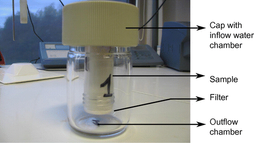
The soil sample is housed in a custom designed fully closed system where a constant pressure prevails, see Figure . This closed system is constituted by a Duran glass tube (LSB inner tube, inner diameter 21.55 mm height 85 mm) containing the soil sample. This tube is screwed to a screw cap which is provided in the screw cap of an outlet reservoir (LSB centrifuge, glass thread GL 60, out diam. 62.3 mm
height 110 mm). The soil container tube is provided with a Borosilicate glass 3.3 Vitra POR filter welded to the tube with a thickness about 2.55 mm to 3 mm, a diameter of about 21.55 mm, and a nominal pore size 1
m–1.6
m (class 5, ISO/4793 = P1,6) for the tests done on kaolin clay and a nominal pore size 16
m–40
m (class 3, ISO/4793 = P40) for the tests done on the mixtures of kaolin and sand. The glass containers are provided of a sufficiently thick wall (3 mm) resistant to centrifugal forces.
Measurements
Sample and water chamber properties
The necessary length sizes (e.g. height of the soil) were measured using a Vernier caliper (accuracy 0.01 mm). The mass of the soil, inlet and outlet water were measured by means of laboratory scales (accuracy 0.01 g). Two types of samples are considered.
The first sample is a commercial processed kaolin Rotoclay HB (Goonvean, St. Austell, UK). This kaolin clay was chosen as reference material because it has been largely used in previous research.[Citation20] Deionized water, produced using a water purification system, was used to prepare the samples and as reference permeant solution. The Electrical Conductivity of deionized water was EC 3.9
S/cm and the pH was about 7.6. The samples are then prepared as a mixture of kaolin clay and deionized water. The amount of water in the mix was set to two times the liquid limit of the clay to obtain a slurry (w = 2
59
= 118
). In order to create suitable reconstituted samples,([Citation21]) the clayey soil and the water were mixed in a dough mixer for 15 min until a homogeneous distribution was observed. Next, the slurry was poured in the glass centrifuge tubes using a vibratory table to remove air bubbles. Then, the sample was housed in an outflow glass reservoir. These samples are then consolidated outside or inside the centrifuge.
The second sample is a mixture of kaolin and Mol sand. This was chosen as a more permeable test, and because comparison is possible with the investigation done in [Citation22]. Mixtures of kaolin and clay have been prepared as follows: both clay and sand were dried in the oven at 105 for 16 h. With a ceramic pestle, some clods of clay were crushed in a ceramic mortar. An amount of 90 g of dry Mol sand with 10 g of dry kaolin clay was mixed with a spoon thoroughly. The soil was then placed in the glass tubes and water was poured from the top to saturate the samples under 1 g conditions until the visible water front reached the base filter. The initial water content of the mixture was about 20
.
The porosity of these soils can be deduced by considering the dry weight of the soil (), total weight after obtaining saturated flow through the sample, (
), and the total volume of the consolidated samples,
. We obtain for the saturated porosity
,
(1)
(1) where
is the density of water. This is the effective saturated porosity. Using the density of the soil, a larger porosity would be obtained; however, for the experiments, we must assume those extra voids to be not accessible (e.g. air bubbles locked inside soil particles).
Sample centre of gravity (COG) and water mass measurements
At the moment, the centrifuge must be stopped to perform measurements. Doing measurements takes around 10 min. The water in the outflow chamber is poured out and weighted, as is the water in the inflow chamber. This gives us the needed water mass measurements. For the determination of the COG of the soil in the tubes, two digital scale professional mini balances were used. The tube is placed horizontally on two sharp holders placed on the balances. The weight of the tube at these two points is recorded and the COG is calculated by means of the equilibrium of forces.
Mathematical model
The centrifuge
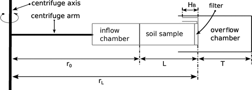
We consider a one-dimensional simplification of the sample. In this, the sample starts (left boundary) at the distance from the centre of the centrifuge and ends at the distance
, see Figure . A water chamber is placed at position
of the centrifuge. A second water chamber is placed at the outflow side, at
. We indicate the height of the water in the inflow chamber as
, and the height of the water in the outflow chamber as l(t). The rotational speed of the centrifuge given in radians per second is denoted by
.
We never consider a completely dry sample, so a cross section of the sample can be in two states: partially saturated characterized by capillary flow and saturated characterized by pores which are completely filled by water.
The piesometric head h is defined from the pressure p as . In a gravitational field, head is the height of the water column at point r giving rise to the given pressure. Within a centrifuge, this analogy is no longer present, but it is nevertheless custom to use h(r). In a centrifuge, a water level of
in the inflow chamber will give rise to a pressure at the top of the sample of
(2)
(2)
Consolidation
As the samples are created in the laboratory, they will undergo consolidation when stresses are applied. We need to be careful to avoid stresses in the centrifuge that are higher than the stresses that occur naturally in the subsurface (we allow depth up to 50 m). On the other hand, the model under consideration will not contain consolidation, so the samples must be prepared and consolidated to the correct stresses before experiments are performed to determine the soil parameters.
The stress in soil mechanics that is important here is the effective stress, on the soil particles, given by (when u is positive), with
the total stress, and u the pore pressure. As we will do unsaturated experiments, we will obtain a negative pore pressure. When the pore pressure is nil, all weights must be carried by the soil particles, and
. Consider the worst case scenario, a sample with void spaces filled for 99.999% of water, which rotates at M rounds per minute. The total stress at the base of the sample in this case is in simplified form given by
(3)
(3) where
is the total density for the soil sample filled with water. We can compare this with stress at a depth D for the same type of soil which is saturated with water but with water table of 0 at this depth, using the formula
, so with
we can identify the depth
(4)
(4) In Table , typical results are given for the table top centrifuge under consideration, so
mm,
mm,
g/cm
.
Table 1 Rotational speed and corresponding total stress at base for a sample with density 
 g/cm
g/cm
 ,
, 
 mm,
mm, 
 mm. Corresponding depth in normal gravity, corresponding g-level at the midpoint of the sample (given by
 , with R the distance from the rotation center), and corresponding stress at that same midpoint are also given.
We see that speeds up to 2400 rpm are allowed, as they correspond in worst case assumption with a depth of 64 m. The stresses in the sample varied rapidly, indicating that consolidation done in the centrifuge can lead to inhomogeneous porosity over the sample. Note further that during normal consolidation, the sample is saturated, so the effective stress will be much lower than the given total stress. However, as soon as drainage starts, the effective stress will be close to the total stress from Table , and compression can occur in the sample. Experimentally, the biggest challenge is hence to consolidate the sample in such a way before the start of the experiments, that no further, or neglectable, compression of the sample occurs during the measurements. Fortunately, changes in height of the sample in the centrifuge are easily recognized, so it is simple to verify this requirement.
As comparison, the samples in [Citation14] underwent centrifugation up to 1500 kPa to determine the soil retention curve from equilibrium curves, and up to 30% in height change between 80 kPa and 1500 kPa was observed, though the recovered soil retention curve matched the pressure plate result.
Saturated flow
Saturated flow () in a sample of fixed length L is determined by Darcy flow, which gives
(5)
(5) where
is the saturated hydraulic conductivity, with initial condition
and boundary conditions at the top (left),
(6)
(6) while for the outflow at the bottom we can consider a water table height
(7)
(7) which is provided by a filled outflow chamber with overflow lip (called the overflow cup), or free outflow, which results instead in the boundary condition
(8)
(8) Equation (Equation8
(8)
(8) ) is due to the fact that excess water must be present at the outflow boundary before droplets can form at the bottom and detach.
One would expect that for the experiments, free outflow is (Equation8(8)
(8) ) sufficient to obtain results. It is technically also easier than using an overflow cup. However, in our unsaturated experiments, problems are encountered when using free outflow. We theorize that this is because the used bottom filter allows air penetration, and during the deceleration faze, air penetrates the bottom part of the sample, greatly increasing the effective stress at the bottom of the sample, and leading to compression at the base and reduced flow. Using a water table at the bottom allows to ensure no air penetration is possible from the base, instead water from the overflow will be sucked into the sample, as we will show in Section 4.5. For future experiments, we plan to or use filters that allow no air penetration, or use (Equation7
(7)
(7) ), so
, or use continuous measurements in the centrifuge which means no deceleration is needed to perform measurements and problems due to air entry at the bottom are avoided.
In practice, to obtain (Equation7(7)
(7) ) we use two outflow chambers, a smaller one with overflow to impose the boundary condition, and a larger one collecting the water that flows out of the overflow and is used in the inverse determination of the parameters.
Solving (Equation5(5)
(5) ) under the given initial and boundary conditions for the unknown flux and
is straightforward.[Citation23] With an inverse method, this allows to optimize the measurements of outflow water in terms of the saturated conductivity
, which is the only soil parameter present in the model. The result can be compared with the classical formula for hydraulic conductivity from two outflow measurements, see e.g. [Citation24],
(9)
(9) where N is defined as
, so it is the g-level at the base of the sample.
In the case of water table height at the base, we derived the analogue formula as
(10)
(10)
Unsaturated flow
When considering unsaturated flow, Richards’ equation must be solved, given by(11)
(11) where q is the flow flux,
is the saturation of the porous media,
the angular speed of rotation (in radians per second),
the saturated hydraulic conductivity, g the gravitational constant, function
the hydraulic conductivity in the unsaturated region and
is called the relative permeability. The initial condition for an experimental run (after measurements) is the original saturation
of the sample where unsaturated and
otherwise (as
). The boundary condition at the top is (Equation6
(6)
(6) ) as in saturated flow when water is present in the inflow chamber, and a no-flow boundary condition otherwise. The very first experiment is always saturated flow, hence unsaturated flow is always unsaturated at the top with possibly a saturated zone at the base.
At the base, we again need to distinguish between an overflow chamber or free outflow. In the last case, we have a no-flow boundary condition if , and otherwise
. If, however, the bottom is kept at a known constant water level (overflow), the bottom will remain saturated, and we have
as in (Equation7
(7)
(7) ), with a saturated zone on top of this boundary, separated from the unsaturated zone at a moving interface, which we denote by
. As the samples are thin, we neglect the occurrence of a drying shock.[Citation12]
Denote by the effective saturation where
is the volumetric water content at saturation and
the residual volumetric water content. We have
, since
. We consider soil hydraulic properties which were proposed by [Citation25]
(12)
(12) where
,
and
are empirical soil parameters. Hence, flow in an unsaturated region can be rewritten in terms of hydraulic pressure head as
(13)
(13) where
is
from (Equation12
(12)
(12) ).
Several numerical solution methods have been proposed to solve (Equation13(13)
(13) ). A common approach is based on using Picard iterations to overcome the non-linearities present in the mode.[Citation26] This approach is applied in the often used HYDRUS code.[Citation27] Another possibility is to leverage the available high accuracy ODE solvers via the method of lines, which was shown to work excellent for Richards’ equation in [Citation28] using a mass-pressure approach. The same good result can be obtained via the method of lines using a saturation formulation or a mixed saturation-pressure formulation, augmented with a global mass balance equation,[Citation19] which is the approach we also follow in this paper, due to its ease of implementation for 1D problems.
So, to solve (Equation13(13)
(13) ), the method of lines is used. In this, a finite volume discretization based on the flux
is done in space on a discrete grid over the domain
. This leads to a system of ODE, which is solved with the Sundials solver, see [Citation23]. Note that the problem is singular where the transition from saturated to unsaturated occurs. To avoid problems, the interface between the saturated and unsaturated part is modelled, effectively splitting the domain in two parts that connect at the interface
, as was done in [Citation19].
The soil parameters occurring in this model are now ,
,
and the properties of the soil retention curve as proposed by van Genuchten,
and
. The effective porosity
can be calculated from (Equation1
(1)
(1) ), while
is determined from the saturated experiments. The value of
is only important in the cases it is possible to go to low saturation values. Before constructing the inverse method to determine the parameters of the soil retention curve, we present in details the solution method for the case of a water table at the base of the sample, as this has not been modelled before.
In details: drainage into an overflow cup
Drainage in an overflow leads to a partial differential equation with a dynamic boundary condition. At the start, and while the centrifuge rotates, water is drained from the sample, see Figure .
Fig. 3 Schematic representation of drainage into an overflow cup. Left: as the water drains, the height is constant. The interface s between partially saturated and saturated zone moves downward. Right: if the centrifuge slows down, part of the water from the overflow cup is sucked into the sample, and the interface s moves upward.
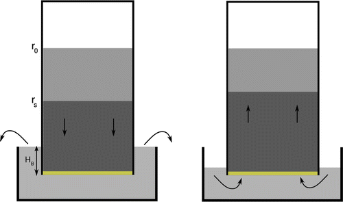
Denote the maximal height of water in the overflow cup,
the water surface area of the overflow cup, A the area of the sample and
the distance from centrifuge axis to the basin water table. The model for drainage in an overflow cup is given by
(14)
(14)
(15)
(15)
(16)
(16)
(17)
(17) with boundary conditions:
(18)
(18)
(19)
(19)
(20)
(20)
(21)
(21)
(22)
(22) Equation (Equation14
(14)
(14) ) describes the saturation evolution in the unsaturated part, the saturated flow formula (Equation15
(15)
(15) ) is derived directly from Darcy’s flow in the saturated part (at the bottom) and determines the water height table
in the overflow chamber described by (Equation16
(16)
(16) ), (Equation21
(21)
(21) ) and the amount of expelled water described by (Equation17
(17)
(17) ), (Equation22
(22)
(22) ). Boundary condition (Equation18
(18)
(18) ) is the no-flow condition at
and can be equally written as
. Condition (Equation20
(20)
(20) ) indirectly determines the position of the interface
, which divides the saturated zone from the unsaturated. Finally, (Equation19
(19)
(19) ) is the boundary condition for hydraulic pressure at the sample end
, which is implied by the hydrostatic pressure of water in the overflow basin. During normal operation, we have
and the interface moves towards
. However, when the centrifuge slows down, the pressure at the base of the sample drops, and water is sucked into the sample. This causes
to drop, and the interface
to move towards
.
During operation, the system moves towards an equilibrium. For this setting, the interface will move faster to its equilibrium position than the saturation profile. Numerically, it is important to avoid instability due to the interface being close to its equilibrium position. This position follows from following lemma.
Lemma 4.1
If during sample drainage (constant , initial
) it holds
, then this holds also
.
Proof
The pressure at the end of the soil sample is caused by the hydrostatic pressure of water in the outflow chamber. From Darcy’s equation, it follows that the flux through the saturated part of the sample is given by(23)
(23) and hence,
(24)
(24) During drainage, we have
, and from (Equation23
(23)
(23) ) it follows that when the saturated front reaches the water level in the outflow chamber, the saturated flux becomes zero. Therefore, the saturated front can from then onward only change due to flux from the unsaturated part, and will hence not continue moving forward. So
,
. Hence,
.
As a consequence of this Lemma, if the interface is within the numerical precision from , we can recast the problem to one with a fixed interface at
. To determine the position of the moving interface, we use an algebraic equation based on total mass balance of the water held in the entire experiment (like in [Citation19]). So, this includes the water contained in the sample, water inside the basin and expelled water captured in the outflow chamber. The resulting system is then a system of differential algebraic equations (DAE), which requires good initial guesses for the time derivatives. Typically, a DAE solver may have problems finding the initial value of
, in this case, providing as initial guess
was sufficient.
Important in the calculation of a solution with a DAE solver is the creation of a suitable space grid. We use a discretization so that the points create a geometric sequence, i.e. if
then
. Therefore,
, where
is the number of discretization points which together with the coefficient
is given as user input, and allows to compute
. We typically use
, which refines the grid towards the saturated interface
.
Inverse determination soil retention curve
The numerical solution of the unsaturated flow results in a computed value of the effective saturation in terms of the applied parameters
, in other words, we obtained
. We also obtain the inflow flux, and the outflow flux, by keeping track of the boundary conditions. Based on the computed
, we can determine the COG of the water, denoted by
, and from the boundary conditions, the amount of inflow water and outflow water, denoted by
and
, respectively. Note that all these measurements are global data; that is, they are independent on the position r.
The computed values should be as close as possible to the measured values at discrete times . We indicate the measured values with a bar, e.g.
. The cost functional to minimize in terms of the parameters is hence
(25)
(25) where
are weights given to the different types of measurements. For the minimization of this cost functional, the Levenberg–Marquardt method (LMM) is used, which gives a solution
. If the value of the cost functional for this solution is sufficiently low, we assume a global minimum is found. Many free implementations of LMM are available, we use the lmdif routine of the minpack library. However, several technical difficulties arise for the considered problem, that are handled in the following way:
Many possible parameters lead to extremely slow initial condition calculations of the DAE system. To alleviate this, we use several tricks: an initial interface
is introduced at
cm. When computing over a relatively wide range of van Genuchten parameters
, we use a dynamic range of initial head
in the unsaturated zone. We choose
such that it is within a specified interval, which in our case is set to
. The reason is that if
appearing in the van Genuchten formula
is small, the relative saturation
is close to
, which can cause a large slow down of the computation of derivatives and interface
. Therefore, we specify a constant value
such that
from which we obtain the
value. We use this value if it falls into our specified range, otherwise the closest edge value of the interval is taken. Knowing the estimates of the optimal values, this dynamic setting of
can be turned off so as to investigate if it influences the final result. Finally, at the interface we set
instead of the expected
.
We specify ranges where parameters are to be expected. Also, as
and/or
, we use logarithmic transformation for these together with the user specified ranges.
Many possible
and
lead to slow or impossible computations of the direct problem—or simply they fall outside of the expected range. To allow the LMM method to recover, we introduce fake costs for these parameters. In practice, those outside the interval are penalized based on the distance from the interval. In case the solver could not finish a computation inside the interval, we penalize with both distances to the edges. The penalization function used is
where
is the interval edge value used for the parameter.
Experiments
Saturated conductivity
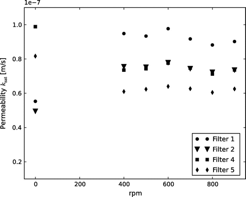
The saturated conductivity was determined for the different filters, and the different soil samples prepared. The results are given in Figure for the first four filters. Here, the results are computed with the model (Equation5(5)
(5) ) where
is optimized to match the measurements, which gives a difference of less than 1.5% compared with the classical formula (Equation9
(9)
(9) ), so these lasts have not been added to the figure.
Important to note here is that the measurements of inflow/outflow water in the centrifuge is sufficiently accurate to obtain good results that are reproducible. The variation in the centrifuge tests can be attributed to measurement uncertainty (duration rotation, correct rpm, startup/slowdown curve), while the difference in obtained permeability for the falling head test can be attributed to the difficulty to keep the filter saturated in the experimental set-up for the falling head test. The given falling head value is the average of two falling head tests, which themselves differ sometimes more than with the centrifuge result. A single falling head test for these filters took more than 150 min, while at 1000 rpm only 4 min of centrifugation time is required.
It is also important to note that in the centrifuge, free outflow is used, so no head value is imposed on the base of the filter. The centrifugal force is sufficiently high to prevent air penetration. The other two filters used were only tested with a normal falling head test. We find for filter 16 m/s, and for filter 17,
m/s. These filters are used for more permeable samples.
This procedure has also been performed on the different soil samples with good results. In this case, the filter permeability is taken into account in the modelling, and the soil sample permeability is obtained. Considering a preconsolidated kaolin sample, we present in Table , next to the already mentioned results, the results of the classical falling head test in a normal gravity field, compared with the average of least squares optimizations (like (Equation25(25)
(25) ), minimize the difference between 10 centrifuge measurements of the outflow water and the model results) at different rpm, to determine
. Note that by using only outflow water, we can also include experiments that show some consolidation, as this is mainly visible in the volume of water of the inflow water chamber. Due to the pre-consolidation, consolidation will, however, be very limited.
Table 2 Permeability of the soil samples and filters.
The last line in Table shows the saturated conductivity for the kaolin-sand mixture based on centrifuge saturated flow. No falling head test was performed on this sample.
Unsaturated conductivity kaolin
For kaolin, the current centrifuge is not able to drain the water as this experiment could only attain 1000 rpm before shaking stopped the centrifuge automatically. Consolidation occurs with only some 3.6 mm of outflow water after 15 h, of which 2.4 can be attributed to drainage and 1.2 due to consolidation. This is too little information to use the model to determine the soil retention curve. The model should also be extended to contain consolidation to process this data.
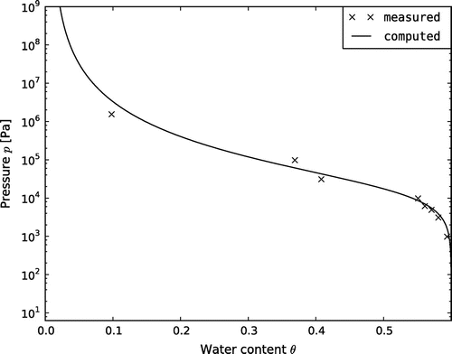
The model can, however, be used to predict the flow behaviour at different rotational speeds. A pressure plate test was done to determine the soil parameters of the kaolin used, from which we obtained cm
,
,
, see Figure . This is combined with saturated conductivity
m/s, with the results presented in Figure . There the evolution of the head and saturation can be seen for rotational speed 1000 rpm (as used), and 6000 rpm, over 60 min of operation.
Fig. 6 Drainage of a kaolin sample in the centrifuge at rpm (top) and
rpm (bottom) over 60 min starting from saturated.
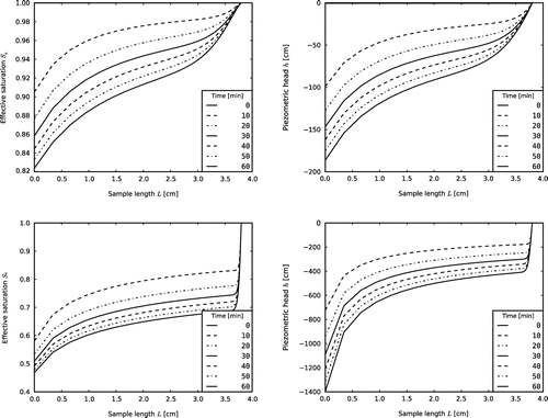
We can conclude that a much higher rotational speed is needed to determine the full soil retention curve, but at 6000 rpm it would be possible to recover most of the curve. However, this might lead to consolidation pressures that are not present in the field. As mentioned, the currently used centrifuge starts to vibrate excessively, which does not allow us to try higher speeds and verify this. The model can, however, be used to simulate the expected behaviour. Note that the model has no problem with the fact that n is close to 1, a typical issue noted in [Citation29]. As drainage with kaolin was not possible, we could not investigate if the adaptations suggested in [Citation29] to the van Genuchten model are required. Instead, we focus next on drainage of sand–clay mixtures.
Unsaturated conductivity sand–clay mixture
The developed centrifuge does perform good for other type of soils which are more permeable than clays. To illustrate this, a drainage experiment was performed on the 100 kPa dry pre-loaded 90% sand–10% kaolin mixture, which was used for the saturated conductivity test. The sample has a void ratio , which corresponds to a porosity of
. Typical values measured for expelled water and gravitational centre (GC) are given in Table . Here, every line is a new measurement, after the given time in seconds. Performing a measurement takes on average 10 min outside of the centrifuge. The entire measurement was done in one day (validating the measurement techniques and procedures, and constructing the mathematical model took up most of the research time, but these are one time setup costs, which need not be repeated).
Table 3 Drainage experiment on 90% sand-10% kaolin mixture. Every line is a new measurement, after the given time in seconds.
The measurements are used in the inverse problem to determine the saturated conductivity and the van Genuchten parameters
and n. The overflow in this experiment is such that the water table was maintained around 2 cm above the base of the sample. We obtain
m/s,
cm
and
if we give the expelled water measurements double the weight of the GC (
,
,
in (Equation25
(25)
(25) )). As we have GC and outflow water measurements, we can also obtain the values taking into account only specific measurements. If we only use GC, we obtain
m/s,
cm
and
, while using only outflow water mass we obtain
m/s,
cm
and
. The experiments and their best fit by the three cases is given in Figure . The GC and outflow results there can be seen as the extremal curves, with depending on the weight given to the experiments, the combined result lying in between. As can be expected, GC matches closest the GC measurements, but has largest error for outflow. This validates the use of both measurement types.
Fig. 7 Experiments performed with the centrifuge. Crosses indicate the measured values, Triangles up the model results for the optimal value taking Gravitational center (GC) and Outflow (MO) into account. Triangles down only using GC, Triangles left using only MO. Full lines indicate the results using the pressure plate fitted soil parameters with two different values of .
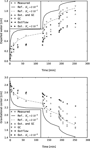
Fig. 8 Measured and inversely determined soil retention curves. Reference curve (Ref.) is the measurements done with ASTM D2325, with the other lines best measurement fit from the model.
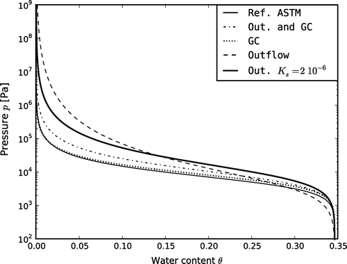
The and n values are compared with those obtained from a pressure plate measurement, which was performed by an outside laboratory according to ASTM D2325 on eight different samples. It took more than two months before the results were obtained. Although the actual experimental time will have been much less, it will have been considerably more than the couple of days needed with the bench scale centrifuge. Of the obtained result, one measurement was identified as erroneous, probably because too little time was given to reach equilibrium (a saturation value of 0.081 at 97885 Pa). Doing a least-squares fit with the van Genuchten model for the soil retention curve, we obtain as best fit
cm
and
, which we combine once with
m/s and once with
m/s to compare with experiments in Figure (labelled Ref., these give the theoretical discrepancy with the measurements as predicted by the mathematical model). The resulting soil retention curves are given in Figure . Observing this result, it is clear that using GC or a combination of GC and outflow gives a very good match with the result from the ASTM D2325 experiment. Using only MO gives a bad match, which is evident in the worse recovery of the n parameter. We also note that the recovered
is an order less than the one determined on another sample of the same material in Table . As the numerical analysis was finished some months after the experiment, this could not be further investigated. Fixing
in the inverse determination to the value obtained in the saturated test,
does not give good results, as is evident in Figures and , where results of the model with that
have been added. We conclude that the sample used in the draining indeed had a lower saturated conductivity, which is consistent with the expelled water found. Independent of differences possible in saturated conductivity, the soil retention curve found matches that of the samples used in the ASTM D2325 experiment. An overview of all parameters, with corresponding determined deviation, is given in Table.
Table 4 Resulting parameters arising in the model. If deviation is given, the parameter was determined via non-linear least-squares, if not given, it was known input.
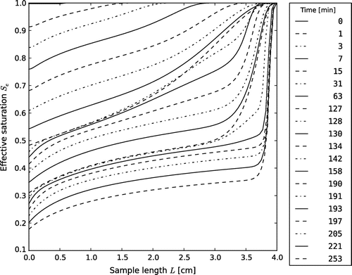
The time evolution of the saturation in the centrifuge, as calculated by the model, is given in Figure . The saturated part at the base of the sample (right) is clearly visible. We see that the lowest saturation is around 0.3, which corresponds to a minimal water content of 0.11. Higher rotational speeds would be required to drain the sample more, and confidently determine the soil retention curve for lower water content. The current centrifuge 2400 rpm corresponds to a maximum capillary pressure of 30,000 Pa (compare with Figure ). In Table , we add the recovered parameters should only the data up to 1200 rpm be used. The recovered parameters are immediately less good, though still usable. Specifically, the value of is off, resulting in a lower estimated permeability than is the case in reality. We conclude that for an accurate recovery of the soil retention curve, it is needed to use an rpm that drains 80% of the sample in the unsaturated zone.
Overall, the experimental values can reasonably be recovered. The two parameters present in this model make for a sufficiently simplified model to obtain a good approximation from the experiments performed. From a geotechnical point of view, the centrifuge determined soil retention curve from outflow combined with GC can be used for predictive models.
The values can also be compared with the results in [Citation22], which for such a mixture gives ,
cm
to
cm
,
m/s for porosities (0.28–0.34). The
value differs a lot, indicating that our sample has a much higher bubbling pressure. The saturated conductivity from the unsaturated test does correspond with this value however. We can conclude that our sample is different from the one in [Citation22] which is apparent also in the different void ratio. We attribute this difference to the different material preparation method. This does proof the danger of using literature data to set soil parameters. Doing an experiment to determine the soil parameters is very important, and the centrifuge method can provides these fast.
Conclusion
We conclude that based on transient data of outflow water and gravitational centre, the soil retention curve can be reconstructed, with a result matching the retention curve as found with an ASTM D2325 experiment.
We expect even better results to be obtained when measurements can be done while the centrifuge is rotating, which will be the next focus in this research. The fact that using only GC gave also good results is interesting. More tests should be performed to investigate if this is a general characteristic.
As the ASTM D2325 measurements allow for the possibility of different regimes in the sample, using a free-form determination for the soil retention curve instead of the van Genuchten model could also be considered. It remains to be seen if the amount of data is then sufficient for a reliable reconstruction. The code to analyse centrifuge experiments can be found at https://gitorious.org/centrifuge-1d/.
Acknowledgments
This research project is funded by IWT (Agency for Innovation by Science and Technology) and Geosound.be, within the project CENPERON (Centrifuge for the determination of the permeability of unsaturated soils), IWT project 110317.
References
- Fredlund DG. The scope of unsaturated soil problems In: Alonso E, Delage P, editors. Proceedings of the 1st International Conference on Unsaturated Soils, Vol. 3 Rotterdam A.A. Balkema; 1995 p. 869–876
- Gourley CS, Schreiner HD. Field measurement of soil suction In: Alonso E,, Delage P, editors. Proceedings of the 1st International Conference on Unsaturated Soils, Vol. 2 Rotterdam A.A. Balkema; 1995 p. 601–606
- Rahardjo H,, Chang MF,Lim TT. Shear strength and in situ matric suction of a residual soil In: Alonso E,, Delage P, editors. Proceedings of the 1st International Conference on Unsaturated Soils, Vol. 2 Rotterdam A.A. Balkema; 1995 p. 637–643
- Singh DN, Kuriyan SJ. Estimation of hydraulic conductivity of unsaturated soils using a geotechnical centrifuge. Can. Geotech. J. 2002;39:684–694.
- Stephens DB. Vadose zone hydrology. New York: CRC Press, Lewis Publishing; 1996.
- Ray RP,, Morris KB. Automated laboratory testing for soil water characteristic curves In: Alonso E,, Delage P, editors. Proceedings of the 1st International Conference on Unsaturated Soils, Vol. 2 Rotterdam A.A. Balkema; 1995 p. 547–552
- Takeshita Y,, Kohno I. Parameter estimation of unsaturated hydraulic properties from unsteady drainage experiments in the laboratory In: Alonso E,, Delage P, editors. Proceedings of the 1st International Conference on Unsaturated Soils, Vol. 2 Rotterdam A.A. Balkema; 1995 p. 567–575
- FredlundDG, RahardjoH.Soil mechanics for unsaturated soils Hoboken (NJ) Wiley; 1993
- Hassler GL, Brunner E. Measurements of capillary pressure in small core samples. Trans. AIME. 1945;160:114–123.
- Nimmo JR, Mello KA. Centrifugal techniques for measuring saturated hydraulic conductivity. Water Resour. Res. 1991;27:1263–1269.
- Nimmo JR, Perkins KS,LewisAM> Methods of soil analysis, Part 4, chapter Steady-state centrifuge Soil Science Society of America, Inc.; 2002 p. 903–916
- Berg EH, Perfect E, Tu C, Knappe PSK. Unsaturated hydraulic conductivity measurements with centrifuges: a review. Vadose Zone J. 2009;8:531–547.
- Forbes P. Discussion of Techien Chen, 1997, ‘an integral method to calculate water saturation in a centrifuge experiment to determine capillary pressure’. Transp. Porous Med. 1998;31:239–244.
- Reatto A, da Silva EM, Bruand A, Martins ES, Lima JEFW. Validity of the centrifuge method for determining the water retention properties of tropical soils. Soil Sci. Soc. Am.2008; 72: 1547–1553.
- Finsterle S, Sonnenborg TO, Faybishenko B. Lima JEFW. Inverse modeling of a multistep outflow experiment for determining hysteretic hydraulic properties In: Proceedings TOUGH Workshop ’98. Berkeley (CA) Lawrence Berkeley National Laboratory; 1998 p. 250–256
- Šimünek J, Nimmo JR. Estimating soil hydraulic parameters from transient flow experiments in a centrifuge using parameter optimization technique. Water Resour. Res. 2005; 41: 9pp
- Nakajima H, Stadler AT. Centrifuge modeling of one-step outflow tests for unsaturated parameter estimations. Hydrol. Earth Syst. Sci. Discuss. 2006;3:731–768.
- Kačur J, Malengier B, Kišon P. A numerical model of transient unsaturated flow under centrifugation based on mass balance. Transp. Porous Med. 2011;87:793–813.
- Kačur J, Nimmo B, Kišon P. Using global characteristics of a centrifuge outflow experiment to determine unsaturated soil parameters. Math. Probl. Eng. 2011; ID 163020: 23pp
- Di Emidio G, Verástegui Flores RD. Monitoring the impact of sulfate attack on a cement-clay mix In: Geocongress 2012, American Society of Civil Engineers; 2012 Available from: http://ascelibrary.org/doi/pdf/10.1061/9780784412121.fm
- Fearon RE, Coop MR. Reconstitution: what makes an appropriate reference material. Géotechnique. 2000;50:471–477.
- Chiu T-F, Schackelford CD. Unsaturated hydraulic conductivity of compacted sand-kaolin mixtures. J. Geotech. Geoenv. Eng. 1998;124:160–170.
- Malengier B, Kačur J, Kišon P. Materials with Complex Behaviour II, chapter Numerical Model for the Determination of the Soil Retention Curve from Global Characteristics Obtained via a Centrifuge. Berlin: Springer 2012. 199–212.
- Sharma JS, Samarasekera L. Effect of centrifuge radius on hycraulic conductivity measured in a falling-head test. Can. Geotech. J. 2007;44:96–102.
- van Genuchten M Th. A closed-form equation for predicting the hydraulic conductivity of unsaturated soils. Soil Sci. Soc. Am. J. 1980;44:892–898.
- Huang K, Mohanty BP, Genuchten MTh. A new convergence criterion for the modified picard iteration method to solve the variably saturated flow equation. J. Hydrol. 1995;178:69–91.
- Šimünek J, van Genuchten MTh Šejna M. Development and applications of the HYDRUS and STANMOD software packages, and related codes. adose Zone J. 2008; 7: 587–600.
- Kees CE, Miller CT. Higher order time integration methods for two-phase flow. Adv. Water Resour. 2002;25:159–177.
- Vogel T, Genuchten MTh, Cislerova M. Effect of the shape of the soil hydraulic functions near saturation on variably saturated flow predictions. Adv. Water Resour. 2001;24:133–144.

