 ?Mathematical formulae have been encoded as MathML and are displayed in this HTML version using MathJax in order to improve their display. Uncheck the box to turn MathJax off. This feature requires Javascript. Click on a formula to zoom.
Abstract
The paper presents the iterative solutions of two coefficient inverse problems (CIPs) arising in frequency sounding and electrical prospecting. An iterative algorithm is constructed to obtain such solutions. Exploiting the Beilina–Klibanov approach to CIPs, this algorithm possesses the new iterative and refinement procedures. These features enhance significantly both the spatial and contrast resolutions of reconstructed coefficients. The computational effectiveness of the proposed numerical technique is demonstrated in computational experiments with two applied CIPs: electromagnetic or acoustic frequency sounding and electrical prospecting of layered media. The Slichter–Langer–Tikhonov formulation is exploited as a mathematical model of the latter.
1 Introduction
The paper addresses a challenging problem of constructing computationally efficient algorithms for coefficient inverse problems (CIPs), i.e. the inverse problems for the partial differential equations where one needs to determine one or several coefficients from a given solution (or its functionals) on some manifolds (see, e.g. [Citation1–Citation4] and references cited there). In this paper, we present a reconstruction algorithm that produces a sequence of iterates that converges to a good estimate of the sought solution from an initial approximation, which is not necessarily close to this coefficient.
Due to both the non-linearity and ill-posedness of CIPs, providing such a convergence is very important for many, if not for all, reconstruction algorithms. Being applied to a CIP, the traditional non-linear least squares approach normally results in a non-convex minimization problem. As a result, the traditional numerical techniques, such as the gradient or Newton-like methods, may not be applicable or they may fail to converge to the true solution or even to its estimates. On the other hand, the methods of global optimization are extremely time-consuming and heuristic. Therefore, the development of such algorithms is of particular interest to quantitative imaging in many applied areas, such as remote sensing, geophysics, medical diagnostics, non-destructive testing and evaluation, etc.
The goal of this paper is twofold. First, this is to present a modification of the Beilina–Klibanov iterative algorithm [Citation1, Citation5, Citation6] for solving some CIPs. Second, this is to demonstrate its computational effectiveness by applying it to frequency sounding and resistivity prospecting of layered media. Introduced by Tikhonov [Citation7] and Cagniard [Citation8] in exploration geophysics, the method of frequency sounding became one of the most popular techniques used in a variety of applications (see, e.g. survey [Citation9]). The term ‘resistivity prospecting’ is associated with geophysical prospecting techniques utilizing measurements of the voltage potential produced by currents injected from the Earth’s surface into the ground (see, e.g. [Citation10]). Unlike the Calderon formulation, which is widely used in electrical impedance tomography with multiple boundary measurements, we utilize the Slichter–Langer–Tikhonov mathematical model [Citation11–Citation13] with a single boundary measurement. Recall that in multiple boundary measurements the number of independent variables in the data is greater than the number of independent variables in the unknown coefficient, whereas in a single boundary measurement they are equal.
To make the underlying idea and technique more descriptive, the one-dimensional (1D) distribution of an unknown coefficient, which is typical for layered media, is considered. However, the algorithm can be generalized to higher dimensions. On the other hand, 1D quantitative imaging itself is widely used in many applications, such as studying Earth interior [Citation14] and seafloor resources,[Citation15] as well as in studying macromolecular biological interactions,[Citation16] nuclear magnetic resonance 1D imaging, mine countermeasures,[Citation6] etc.
One approach to constructing the computational algorithms for CIPs was recently proposed in [Citation2]. It is based on Carleman estimates allowing for constructing some strictly convex least squares functionals at each step of a layer-stripping procedure with respect to the spatial variable. In [Citation1, Citation6] the layer stripping procedure with respect to the real-valued parameter of the Laplace transform combined with an iterative procedure for treatment of the so-called tails was developed and applied to solving D (
) CIPs. Unlike the numerical techniques described in [Citation1, Citation6], we do not solve an overdetermined boundary value problem when determining the initial approximations. Also, we do not use the marching scheme for performing iterates with respect to the parameter of the Laplace transform. Instead of the WKB (i.e. short wave) approximations, we use the exact solutions for a homogeneous medium in order to initialize the iterative procedure. The main distinctive feature of the proposed algorithm is the refinement procedure, in which we search for a better approximation performing matching the interior field generated by the iterative solution by the solutions of the forward problem in the region of interest. It follows from the results of numerical experiments that these novelties are advantageous. They allow for more accurate estimates of the unknown coefficient.
The paper is formatted as follows. In Section 2, we formulate an inverse problem of frequency sounding. In Section 3, we describe the proposed algorithm. In Section 4, the refinement procedure is outlined and dicussed. In Section 5, we conduct the numerical study of the proposed algorithm by computer simulations of both the frequency sounding and electrical prospecting of layered media. We conclude our investigation in Section 6.
2 An inverse problem of frequency sounding
As in [Citation17], we consider a pulse wave emitted at and propagated through the Epstein layer, which is the half-space
filled with the lossless inhomogeneous medium, such that the wave propagation speed is variable for
and it is constant for
. In this case, the initial boundary value problem for the hyperbolic equation governing the wave propagation is given by
1
1
2
2 Here,
is the speed of propagation of electromagnetic or acoustic waves. We emphasize that we do not impose the smallness assumption on the coefficient
.
Inverse Problem.Let the functionsatisfies the initial boundary value problem (Equation1
1
1 )–(Equation2
2
2 ). Given the function
and parameters
, such that
for
, find the variable speed
on
.
The traditional approach to solving this problem consists of reducing the wave Equation(Equation11
1 ) to the Helmholtz equation via the Fourier transform and constructing the globally convergent algorithms. To the author’s knowledge, there exist three such algorithms. The first algorithm (see [Citation18]) is based on the so-called trace (asymptotic) formulae, whereas the second one (see [Citation19]) utilizes the non-linear Riesz transform allowing for reducing the equation to the Volterra integral equation. The third algorithm is based on the convexification method.[Citation2] Unlike these algorithms, we apply the Laplace transform to the problem (Equation1
1
1 ) and(Equation2
2
2 ). The Laplace transform was also used in [Citation1] for solving the similar inverse problem for the wave equation.
To justify the applicability of the Laplace transform, we assume that for all
. Here,
and
is the given parameter. Then, applying the Laplace transform
to the problem (Equation1
1
1 ) and (Equation2
2
2 ) and introducing the dimensionless variables
, one can reduce it to the
-parametric family of elliptic boundary value problems
3
3
4
4
5
5 Here,
is the refraction coefficient, where
, and
and
are speeds of the wave propagation in the Epstein layer and homogeneous medium. Due to injectivity of the Laplace transform, the existence of a unique solution of (Equation3
3
3 )–(Equation5
5
5 ) follows from classical arguments. Also, for a sufficiently smooth refraction coefficient
(see, e.g. [Citation2]). In practice, the surface admittance
or impedance is measured in the interval
. Therefore, introducing by analogy with [Citation2] the new function
6
6 we obtain the family of problems
7
7
8
8 Introducing one more function
and differentiating (Equation7
7
7 ) and (Equation8
8
8 ) with respect to the
-variable, we obtain the mathematical model that does not contain the unknown refraction coefficient
9
9
10
10 Note that for every
the Equation (Equation9
9
9 ) is integro-differential because of the representation
11
11 Thus, the inverse problem of frequency sounding is reduced, basically, to estimating the interior field
given the data
. Indeed, once such an estimate is obtained, the functions
and
may also be estimated from (Equation11
11
11 ) and (Equation7
7
7 ).
3 Description of the algorithm
It follows from the previous section that if both functions and
are known, then the solution of the inverse problem can be found in the closed form from the Equation (Equation7
7
7 ). Another important observation is that if the function
is known, then the problem (Equation9
9
9 ) and (Equation10
10
10 ) is linear with respect to
. We elaborate these observations as follows.
Initialization step We determine the initial approximations of the functions and
as the exact solutions to the boundary value problems (Equation7
7
7 )–(Equation10
10
10 ) for
. That is, we assign
It should be mentioned that the initial approximations determined in [Citation6] from the numerical solution to an auxiliary overdetermined problem are very close to our choice.
Step 1 Beginning with , we start the iterative process. Assume that the
th successive approximation
has been determined for all parameters
. Then, given
, we determine
as follows. For an arbitrary fixed
denote
, where the differential operator from
to
. Let
and consider the Tikhonov functional
12
12 where
is the regularization parameter. Since the operator
is linear with respect to
, it follows from the theory of ill-posed problems (see, e.g. [Citation20, Citation21]) that this functional is strictly convex. Then, it follows from the Weierstrass theorem and strict convexity that there exists its unique minimizer
in a set
, and any method of constrained optimization converges to it for every fixed parameter
. Then, we assign
. The regularization parameter
is chosen consistently with the level of noise
in the ‘measured’ data
, i.e. such that
. In the numerical experiments we used a priori parameter choice
, where
(see, e.g. [Citation20, Citation21]).
Step 2 We update the function for every parameter
as follows:
13
13
14
14
15
15 Step 3 Let
be a certain number that does not depend on
. We update the refraction coefficient as
16
16 where
, and set
for
and
.
Step 4 Update the function by first solving the problem
17
17
18
18 and then determining the functions
19
19
20
20
21
21 for
.
Stopping ruleThe iterative process continues until a stopping rule is fulfilled. If the level of noise in the data
is given or it can be estimated, then it is natural to stop the process at the iterate
22
22 where the function
is determined from the solution of the original problem (Equation1
1
1 ) and (Equation2
2
2 ) with
for every successive approximation
. Note that since the norm in (Equation22
22
22 ) represents the residual functional on
, the number
plays the role of the regularization parameter for the entire iterative process. Since in computing we deal with the discrete functions defined on grids, the derivatives are approximated by their finite difference analogous and the integrals in (Equation13
13
13 )–(Equation15
15
15 ) – by appropriate quadratures.
Note that if the level is fixed, then any regularizing algorithm, including the proposed one, provides just a certain approximation of the true refraction coefficient
. By choosing
(see, e.g. [Citation20], Chapters 3 and 4), one can easily obtain an error estimate for all
23
23 where
and the number
does not depend on
and
; it does not generally imply the convergence
as
. Therefore, the role of numerical experiments in estimating the approximation error is crucial.
4 Refinement of 

It follows from the previous section that the proposed algorithm provides a sufficient proximity of successive approximations to the true coefficient if the level of noise is sufficiently small. In practice, however, it is more typical than exceptional that such a condition is not fulfilled. In this case, the approximation
may not possess high spatial and contrast resolutions, i.e. the quantitative imaging may be problematic. To alleviate this restriction, we propose to take advantage of knowledge of the pair
everywhere in
, where
24
24 and
, where
is the set of sufficiently smooth functions
(e.g.
). We observe that although for a certain
the function
may be close to the Laplace transform of the solution of the original problem (Equation1
1
1 ) and (Equation2
2
2 ), it does not satisfy it. This observation motivates matching the interior field
with the Laplace transform
of the solution of the original problem (Equation1
1
1 ) and (Equation2
2
2 ). We are interested in finding a new approximation of
whose error estimate is better than the error estimate for
.
To find such an approximation, we consider the injective and continuous map , where
, and minimize the Tikhonov functional
25
25 where
. Because the set
is bounded and compact, the existence of a unique minimizer in a neighbourhood of the function
follows from the Weierstrass theorem and strict convexity of
. Note that the estimate (Equation23
23
23 ) implies
.
Let be the minimizer of the Tikhonov functional (Equation25
25
25 ). It follows directly from [Citation22] that if the reqularization parameter is chosen as
, then
26
26 where
. This is the motivation of the refinement procedure.
5 Numerical study
In this section, we apply the proposed algorithm to the inverse problems of frequency sounding and electrical prospecting of layered media.
5.1 Computer simulation of frequency sounding
To generate the frequency sounding data , we solved numerically the problem (Equation3
3
3 )–(Equation5
5
5 ). To provide a high accuracy of reconstruction, we represented the solution of this problem in the form
, where
is its solution for
, and considered the problem
27
27
28
28
29
29 for every
. The integro-interpolation (or balance) method (see [Citation23], Section 3.2) was used to construct the homogeneous difference scheme for this problem with both the smooth and piecewise-smooth refraction coefficients. Note that if the refraction coefficient is smooth, then we obtain the approximation of order two. The resulted system of linear equations was numerically solved by a stable version of the elimination method (see [Citation23], Section 1.1). Also, since the solution of this difference problem approximates the solution of the problem (Equation27
27
27 )–(Equation29
29
29 ), the function
approximates
. The level of error of this approximation depends on several factors, such as smoothness of the refraction coefficient, grid, CPU, etc. In the numerical experiments, we utilized the uniform grids containing from 64 to 100 nodes, and the refraction coefficient was assumed to be either smooth or piecewise-constant. Under such conditions, it was estimated from comparison with the model refraction coefficients that the level of noise
in the data varied approximately from
(if
is smooth) to
(if
is piecewise-constant). Since
and
, where
the two-point problem for the function
has the form
30
30
31
31
32
32 where
, and the boundary data is given by
33
33 In computing, the operator
is understood in the sense of differentiating an interpolating cubic spline of
. The non-linear problem (Equation30
30
30 )–(Equation33
33
33 ) has two unknowns
, and it looks similar to the problem (Equation9
9
9 ) and (Equation10
10
10 ). Therefore, we applied the algorithm described in the Section 3. In the iterative process, we updated the refraction coefficient as
where
In the numerical experiments, the integrals were approximated by a quadrature formula. Although from a theoretical standpoint, the parameter
can be chosen arbitrarily, in the numerical experiments it was chosen to provide the best accuracy of reconstruction of some benchmark refraction coefficients. The function
at
was updated as follows. We first solve numerically the two-point problem (Equation27
27
27 )–(Equation29
29
29 ) with the
th successive approximation
of the refraction coefficient. Let
be such a solution. Then the updated function
and its two derivatives were computed as
34
34 Once the inequality
was fulfilled, the iterative process was terminated. The approximate solution
was refined as follows. We defined the function
35
35 and minimized the functional
36
36 Since the functional
is strictly convex, the Powell method with the initial approximation
was used to find its minimizer.
We first simulated electromagnetic frequency sounding of dry layered soil, which is usually performed by ground penetrating radars for the purpose of land mine detection and classification. We assumed that the relative magnetic permeability and electrical permittivity of the background media are equal to 1, and . The realistic values of
(see, e.g. [Citation24]) were used in the numerical experiments. The distribution of the relative electrical permittivity of a subsurface land mine was simulated by a Gaussian curve. Figure shows the typical boundary data
generated by this mine embedded in the homogeneous background (air) with
. In Figure , the effect of refinement of
via fitting the interior data in comparison with refinement via fitting the boundary data is shown. In this experiment, the non-perturbed frequency sounding data were used, and the regularization parameter
providing the best accuracy was chosen
.
Figure 1. The simulated electromagnetic frequency data in the interval
. The noiseless data are shown by bullets and the data corrupted by noise at the level of 5% are shown by asterisks.
![Figure 1. The simulated electromagnetic frequency data φ¯(s) in the interval [1,10]. The noiseless data are shown by bullets and the data corrupted by noise at the level of 5% are shown by asterisks.](/cms/asset/7dd5029e-1e4f-46db-98fa-d40329c13e50/gipe_a_872101_f0001_b.gif)
Figure 2. Reconstructions of the relative electrical permittivity of a single mid-contrast land mine in the air: (1) without refinement (dashed), (2) with refinement using the boundary data (asterisks) and (3) with refinement using the interior data (bullets). The original distribution is shown by a solid line.
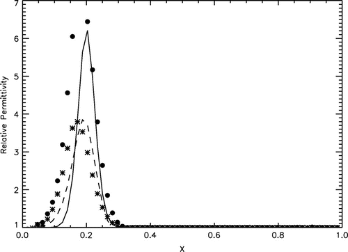
Figure 3. Recovering the relative electrical permittivity of a single mid-contrast land mine from the perturbed data (the level of noise is 5%) without refinement (asterisks) and with refinement (bullets).
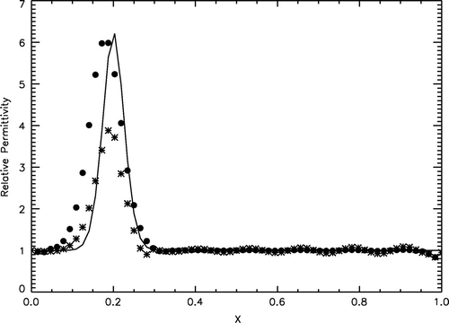
Figure 4. Reconstructions of the relative electrical permittivity of a single low-contrast (left), mid-conrast (middle) and high-contrast (right) land mine in the air. The results of reconstruction are shown by asterisks (without refinement) or by bullets (with refinement). The original distribution is shown by a solid line.
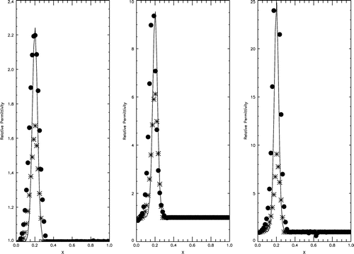
Figure 5. Reconstructions of the relative electrical permittivity of a low-contrast land mine embedded in clutter at without (asterisks) and with (bullets) refinement. The original distribution is shown by a solid line.
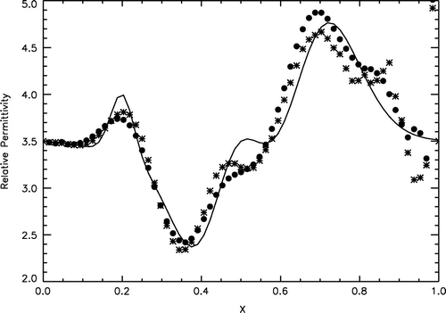
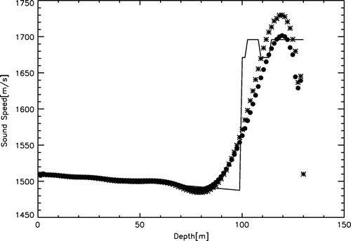
Figure 6. Results of recovering the sound speed profile from the data obtained on the see surface: reconstructions without (asterisks) and with (bullets) refinement. The original sound speed profile is shown by the solid line.
To demonstrate the robustness of the proposed algorithm, we simulated the perturbed data by adding the normally distributed noise to , i.e.
, where
is the normally distributed pseudo-random vector with mean zero and standard deviation of 1, and
is the model standard deviation chosen as
, where
. The perturbed data are shown in Figure . Figure shows the mean relative electrical permittivity obtained from a sample containing 25 realization of the pseudo-random vector
. Since robustness of the proposed algorithm was also confirmed in all other numerical experiemnts, we limit our next demonstrations by the results of recovering the material properties from the noiseless data.
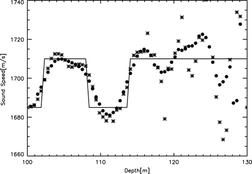
Figure 7. Results of recovering the sound speed profile from the data obtained on the see floor: reconstructions without (asterisks) and with (bullets) refinement. The original sound speed profile is shown by the solid line.
Since the land mines may be filled with the different explosives and they may be covered by either metallic or plastic materials, their averaged relative electrical permittivity may range from 2 to 25 or more units. Figure shows the results of reconstruction for the different contrasts. In all such cases, the effect of refinement was significant.
In practice, even a near subsurface, where land mines are usually embedded in, is not homogeneous. This may be due to variations of sand and clay porosity, water saturation, presence of abris, etc. These inhomogeneities lead to unwanted variations in GPR signals that are referred to the clutter. We simulated the model clutter containing a continuously inhomogeneous layer with the relative electrical permittivity ranging from 2.4 to 4.75. Such a variation is typical, for instance, for a mixture of sand and clay with the variable porosity and water saturation. We investigated how the presence of clutter affects reconstruction of the relative electrical permittivity of land mines. The reconstructed relative permittivities are shown in Figure . Clearly, the presence of clutter affects significantly the quality of quantitative imaging. The higher the contrast the lower the quality, though a near surface land mine may still be detected and classified.
Also, we simulated acoustic frequency sounding of layered marine environments. In these cases, , where
is the sound speed profile, and
is the reference sound speed. In the numerical experiments, we used the values of parameters typical for the shallow waters and water-saturated sediments.(see, e.g. [Citation25]) To simulate the sound speed profile in the water column, we used the simplified Wilson’s formula [Citation26]
where
is the temperature (Celcius),
is the depth (m) and
is the salinity (psu). The sound speed profile in the sea floor sediments was simulated by a piecewise-constant average compressional wave speed in the range from 1685 to 1710
. Inversion was performed for the dimensionless parameter
ranging from 1 to 10 on a grid containing 64 nodes. Figure shows the results of inversion from the surface of the water column. Clearly, the proposed algorithm performed nicely for the water column, which is of particular interest to underwater acoustics. However, the fine structure of the sediment layer was not resolved. The results of inversion from the sea floor shown in Figure demonstrate the effectiveness of refinement, though the accuracy of quantitative imaging diminished as we advanced into the sediment layer.
5.2 Computer simulation of electrical prospecting
Recovering the subsurface conductivity in a horizontally stratified Earth from the observed surface potential was originated by Slichter [Citation12] and Langer [Citation11]. In [Citation13], Tikhonov established the uniqueness result for their formulation. In [Citation27], the SLT inverse model, as well as the logarithmic derivative of the conductivity function and Hankel transform was used to justify the local strict convexity and smoothness of the residual functional. In this section, we apply the proposed algorithm for the SLT inverse problem.
Assume that the upper-half space is filled with a conductive medium, such that , and there exists a thin layer
, such that its conductivity is constant and equals to
. The lower half-space
is supposed to be filled with a dielectric. Introduce the cylindrical coordinates
and consider a point-like current electrode placed at the point
. Because of the cylindrical symmetry, the voltage potential
generated by this current satisfies the following conditions.
37
37
38
38
39
39 We formulate the following inverse problem.
Let the function satisfies the boundary value problem (Equation36
36
36 )–(Equation38
38
38 ) and it is associated with the conductivity
. However, the trace
of
on the surface
is unknown. Instead, its approximation
, such that
, is known. Given
, find an approximation of
in the finite layer
.
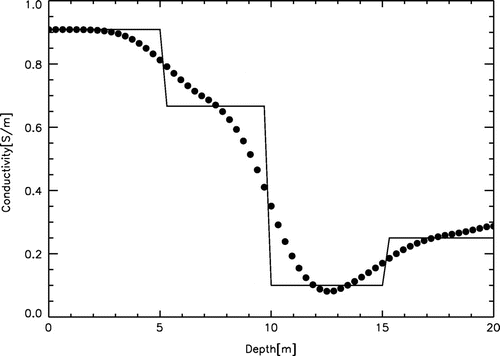
Figure 8. The results of inversion of the surface voltage potential with and without refinement are shown by bullets. The original distribution of conductivity for the four-layer medium is shown by the solid line.
Following,[Citation13] we first apply the zero-order Hankel (Fourier-Bessel) transformto the problem (Equation36
36
36 )–(Equation38
38
38 ) and introduce the new variables
40
40
, where
and
Then, the problem (Equation36
36
36 )–(Equation38
38
38 ) is reduced to the two-point problem
41
41
42
42
43
43 Here,
. We observe the similarity of this problem with the problem (Equation3
3
3 )–(Equation5
5
5 ) modelling frequency sounding of layered media. The only difference is the surface boundary conditions (Equation41
41
41 ), which is due to the presence of the current electrode. This observation motivates the following reformulation of the inverse problem.
Let the functionbe a solution of the problem(Equation40
40
40 )–(Equation42
42
42 ) that corresponds to
, but
is unknown. Instead, an approximation
, such that
, where
and
is given, find an approximation of
in
.
Since the SLT model (Equation4040
40 )–(Equation42
42
42 ) is similar to the frequency sounding model (Equation3
3
3 )–(Equation5
5
5 ), the specific procedure for reconstructing the conductivity is the same as described in the Section 5.1. However, since the travel time transformation (Equation39
39
39 ) maps a uniform grid
onto a non-uniform grid
, such that
one needs to transform the reconstructed refraction coefficient back to the conductivity distribution. Let
be the values of the reconstructed refraction coefficient on an arbitrary uniform grid
. Then, to obtain the values
of the reconstructed conductivity on
, we interpolated the values
from the uniform grid
onto the non-uniform grid
corresponding to the uniform grid
. In this case, the ‘optimal’ dimensionless range of the parameter
, i.e.
, was chosen as
. It is demonstrated in Figure that the refinement procedure does not provide the improvement of
. This is due to the diffusive character of the stationary electric field described by the SLT model (Equation40
40
40 )–(Equation42
42
42 ).
6 Conclusions
We modified the Beilina–Klibanov iterative algorithm for quantitative imaging of layered media. Compared to the original algorithm, it possesses the new iterative and refinement procedures. The modified algorithm was tested in several numerical experiments with the data simulated for electromagnetic and acoustic frequency sounding, as well as for electrical prospecting of layered media. The results of testing demonstrated the computational effectiveness of the modified algorithm when recovering the permittivity of the near surface targets from the electromagnetic frequency sounding data. However, in cases of acoustic sounding and electrical prospecting of geophysical layered configurations, the modified algorithm exhibited the so-called smoothing property (see Figures –). Apparently, this is due to the use of the -norm in the Tikhonov functional (Equation25
25
25 ). Therefore, applying the total variation regularization to these problems will be the subject in our further study.
References
- Beilina L, Klibanov MV. Approximate global convergence and adaptivity for coefficient inverse problems. New York (NY): Springer; 2012.
- Klibanov MV, Timonov A. Carleman estimates for coefficient inverse problems and numerical applications. Utrecht: VSP; 2004.
- Lavrentiev MM, Romanov VG, Shishatskii SP. Ill-posed problems of mathematical physics and analysis. RI: AMS Providence; 1986.
- Romanov VG, Kabanikhin SI. Inverse problems for Maxwell’s equations. Utrecht: VSP; 1994.
- Karchevsky AL, Klibanov MV, Nguyen L. The Krein method and the globally convergent method for experimental data. Appl. Num. Math. 2013;74:111–127.
- Kuzhuget AV, Beilina L, Klibanov MV, Sullivan A. Quantitative image recovery from measured blind backscattered data using a globally convergent inverse method. IEEE Trans. Geosci. Remote Sens. 2012;51:1–12.
- Tikhonov AN. Mathematical basis of the theory of electromagnetic sounding. USSR Comput. Math. Mathem. Phys. 1949;5:797–800.
- Cagniard L. Basic theory of the magnetotelluric method of geophysical prospecting. Geophysics. 1953;37:605–635.
- Khruslov EYa, Shepelsky DG. Inverse scattering method in electromagnetic sounding theory. Inverse Probl. 1994;10:1–37, 507–522.
- Zhdanov MS, Keller GV. Geolectrical methods in geophysical exploration. New York (NY): Elsevier; 1994.
- Langer RE. On the determination of earth conductivity from observed surface potentials. Bul. AMS. 1936;42:747–754.
- Slichter LB. The interpretation of the resistivity prospecting method for horizontal structures. Physics. 1933;4:307–311.
- Tikhonov AN. On the uniqueness of the solution to the problem of electrical prospecting. Doklady USSR. 1965;LXIX:207–211.
- Spichak V. Electromagnetic sounding of the earth’s interior. New York (NY): Elsevier; 2011.
- Key K. Marine electromagnetic studies of seafloor resources and tectonics. Surv. Geophys. 2012;33:135–167.
- Stewart ME, Mack NH, Malyarchuk M, Soares JANT, Lee TW, Gray SK, Nuzzo RG, Rogers JA. Quantitative multispectral biosensing and 1D imaging using quasi-3D plasmonic crystals. Proc. Natl. Acad. Sci. USA. 2009;1–3:17145–17148.
- Tamasan A, Timonov A. On a new approach to frequency sounding of layered media. Num. Func. Anal. Optim. 2008;29:470–486.
- Chen Y, Rokhlin V. On the inverse scattering problem for Helmholtz equation in one dimension. Inverse Probl. 1982;8:365–391.
- Sylvester J. Layer stripping. In: Colton B, Engl HW, Louis AK, McLaughlin JR, Rundell W,editors. Surveys on solution methods for inverse problems. New York (NY): Springer-Verlag; 2000. p. 83–106.
- Ivanov VK, Vasin VV, Tanana VP. Theory of linear Ill-posed problems and its applications. Utrecht: Walter de Gruyter; 2002.
- Tikhonov AN, Leonov AA, Yagola AA. Nonlinear Ill-posed problem. New York (NY): Elsevier; 2001.
- Klibanov MV, Bakushinsky AB, Beilina L. Why a minimizer of the Tikhonov functional is closer to the exact solution than the first guess. J. Inv. Ill-Posed Probl. 2011;19:83–105.
- Samarskii AA. The theory of difference schemes. New York (NY): Marcel Dekker; 2001.
- www.asiinstr.comtechnicalDielectric%20Constants.htm
- Rajan SD, Anand GV, Nagesh PV. Joint estimation of water column and sediment acoustic properties from broadband towed array data using modal inverse method. J. Acoust. Soc. Am. 2006;120:1324–1334.
- Wilson BD. Equation for the speed of sound in sea water. J. Acoust. Soc. Am. 1960;32:1357–1373.
- Mukanova B. An inverse resistivity problem: 2. Unilateral convexity of the objective functional. Appl. Anal. 2009;88:767–788.
