 ?Mathematical formulae have been encoded as MathML and are displayed in this HTML version using MathJax in order to improve their display. Uncheck the box to turn MathJax off. This feature requires Javascript. Click on a formula to zoom.
Abstract
The planned new generation of extremely large telescopes (ELT) requires highly efficient algorithms for its adaptive optics systems. Recently, a new iterative reconstruction approach for multi conjugate adaptive optics (MCAO) and multi object adaptive optics (MOAO) was introduced that computes the mirror corrections without the use of matrix-vector multiplications. The method splits the MCAO/MOAO problem into three subproblems – wavefront reconstruction, atmospheric tomography and mirror deformation – sequently. If an AO system uses laser guide stars, then the reconstruction methods have to be extended in order to consider the cone effect and the tip/tilt indetermination. For the reconstruction of an atmosphere with correct tip/tilt we assume that additional measurements from a tip/tilt sensor are available, and propose two iterative reconstruction methods for the atmosphere. In the first approach, the tip/tilt reconstruction is included into the atmospheric tomography, whereas in the second approach the tip/tilt is reconstructed separately and added to the atmosphere after the atmospheric tomography. Both algorithms are tested numerically. The reconstruction quality of our methods is evaluated for ELT.
1 Introduction
The image quality of large ground based-telescopes is severely affected by atmospheric turbulences. Adaptive optics systems correct for the disturbances by using appropriately shaped deformable mirrors (DM) to obtain sharper images. The shape of the DMs depends on the turbulences in the atmosphere and has to be recomputed with a frequency of 500–1000Hz, which requires powerful reconstruction methods for future systems with thousands of degrees of freedom. An introduction to adaptive optics can be found in [Citation1–Citation3].
Adaptive optics systems of the new generation, as multi conjugate adaptive optics (MCAO) and multi object adaptive optics (MOAO) aim at a correction not only into a single direction on the sky but over a large field of view. This can be achieved by the use of measurements from several artificially created stars, laser guide stars, pointed at different directions and several DM, which are conjugated to different heights in the atmosphere. The mirror shapes have to be obtained with a tomographic algorithm. For the description of an MCAO system, we refer to [Citation4, Citation5]. Contrary to MCAO, an MOAO system has a separate mirror to correct for each direction of interest, i.e. for each observed scientific object, see [Citation6, Citation7].
In [Citation8], we have proposed a reconstruction method that solves the three required subproblems – wavefront reconstruction, atmospheric tomography, mirror fitting – sequently. In particular for the wavefront reconstruction and the mirror fitting we have presented accurate as well as fast methods. For the atmospheric tomography, we have used a fast iterative algorithm, the Kaczmarz method. However, so far we only considered measurements from natural guide stars for the reconstruction of the atmosphere. When using laser guide stars, additional effects have to be taken into account, e.g. the cone effect and tip/tilt indeterminacy due to the nature of the laser guide star (see [Citation1] for details). The goal of the paper is to investigate a variant of the Kaczmarz iteration that takes these effects into account.
Due to the finite height of the laser guide star, the light is not propagated through the atmosphere in a cylindrical but rather in a conical form. This so called cone effect can be taken into account by a redefinition of the operator that describes the measurements from a laser guide star.
Tip/tilt indeterminacy refers to the impossibility to reconstruct the correct linear part of the atmosphere from laser guide star measurements only. This is related to the fact that the laser light passes all turbulent layers twice – on its way up and down. In order to reconstruct the tip/tilt correctly, additional natural guide stars and tip/tilt sensors are used.
In most of the proposed numerical methods for MCAO (or for the atmospheric tomography problem), a large system matrix is set up that maps the atmospheric turbulences to the sensor measurements of incoming wavefronts from the guide stars. The implementation of cone effect and tip/tilt indetermination into the system matrix is straight forward, see, e.g. [Citation9]. The solution of the resulting matrix vector system involves either the computation of the generalized inverse of the underlying matrix [Citation10] or iterative methods for the solution of the linear system.[Citation11–Citation21]
In the following, we will propose two methods for the combination of laser guide star measurements with the natural guide star measurements in the framework of the Kaczmarz reconstructor proposed in [Citation8]. As in the therein proposed three-step approach, we will assume that we already have the incoming wavefronts from the laser guide stars, that is, we have already reconstructed the wavefronts from Shack–Hartmann wavefront sensor measurements. The sensor can mathematically be described as the averaged gradient of the wavefront on the subapertures,1.1
1.1 and
, respectively (see [Citation1], Section 5.3.2). For the inversion of the operator
, the Cumulative Reconstructor (CuRe) or CuReD, a variant of CuRe with domain decomposition, is used.[Citation22–Citation24] These algorithms are currently the fastest ones available, and will guarantee – together with the Kaczmarz iteration and the fitting step – a reconstruction for MCAO/MOAO well within the time frame available for the planned extremely large telescopes (ELT).
The paper is organized as follows. In Section 2, the model for atmospheric tomography is presented followed by a derivation of some mathematical properties of the tip/tilt sensor models. In Section 3, two methods for atmospheric tomography with tip/tilt correction are proposed, the separate and the integrated tip/tilt reconstruction. The corresponding numerical results and computational complexities of both methods are presented in Section 4.
2 Atmospheric tomography
The goal of atmospheric tomography is the reconstruction of turbulent layers
, located at heights
,
from a combination of natural and laser guide star measurements. We assume that
different laser guide stars, located at finite height in directions
,
, are available, as well as
tip/tilt measurements from tip/tilt sensors aligned to natural guide stars in directions
,
. Associated to each laser guide star, we have measurements of the incoming wavefront
, and for each natural guide star measurements
.
Due to the fact that a laser guide star is located at a finite altitude, the models for the propagation of the light from laser guide stars and natural guide stars differ slightly, as we will point out below. Following Fusco et al. [Citation25], we only aim at the reconstruction of a finite number of turbulent layers in the atmosphere. Each layer is represented as a function . For simplicity, we will drop the coordinate for the height of the layer, which is implicitly assigned to each layer via its number.
Note that the restriction to the reconstruction of a finite number of functions defined on a plane instead of reconstructing a volume reduces the ill-posedness of the problem.
Let denote a disc with radius
, centred at the origin and representing the telescope, i.e.
Following [Citation25], the incoming wavefront from a natural guide star in a direction
is given as
2.1
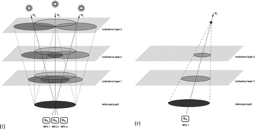
2.1 see Figure (l). In contrast, the light from a laser guide star propagates in a cone towards the telescope, see Figure (r). The measured wavefronts from laser guide stars are therefore given by
2.2
2.2 The parameter
depends on the location of the layer and the laser guide star and is defined as
2.3
2.3 where
denotes the height of the laser guide star.
At altitude , we can only reconstruct what is ‘seen’ by the guide star sensors, i.e. within the area
2.4
2.4 Here,
2.5
2.5 If
, we will frequently drop the second parameter, that is,
2.6
2.6 Thus, the set
is simply the union of shifted versions of
, see also Figure . Please note that, even at a large altitude, there will be a significant overlap of the shifted versions of
due to the small field of view.
Figure 1. Atmospheric tomography: measurements from natural guide stars (l) and influence of the cone effect (r).
In what follows, we will consider as a function in the spaces
, the space of square integrable functions or the Sobolev space
, which is defined by
with
where
is a fixed parameter. It is well known that
is a Hilbert space with inner product
2.7
2.7 Next, we collect all layers in a vector
,
and define an inner product via
where we can choose either the
or the
inner product on the right hand side. The parameters
are the (known) relative strengths of layers in the atmosphere, fulfilling
2.8
2.8 The parameter
denotes the
-profile of layer
, that is an additional information about the strength of the turbulence on that layer and is, therefore, used as a weighting factor for the inner product.
The task is to reconstruct the atmosphere from measurements
. As mentioned in Section 1, the reconstruction from the incoming laser guide star wavefronts leads to a wrongly reconstructed tip/tilt. In order to obtain a correct reconstruction of the atmosphere, additional tip/tilt sensors are needed, which will be investigated in the following.
2.1 Some mathematical properties of the operators describing tip/tilt sensors
The MCAO / MOAO systems which will be used, e.g. at the European extremely large telescope (E-ELT), use additional tip/tilt sensors to determine the tip/tilt of an incoming wavefront from additional natural guide stars. A mathematical model for the sensor measurements of an incoming wavefront from a natural guide star is given by2.9
2.9
2.10
2.10
2.11
2.11
, i.e. it is assumed that the sensor measures the average values of the partial derivative of the incoming wavefront over the whole aperture. We wish to remark that other models for the measurements are also frequently used, e.g. the RMS best-fit tilt to the wavefront, see, e.g. [Citation15]. Please note that the operator
is not well defined on
; thus, we will here consider it in the
setting only. The reconstruction algorithms presented later will always use the adjoint operator
, which will be derived in the following section.
2.1.1 The operator 
 defined on
 spaces
We consider the operatorLet us now derive the adjoint operator
For
, set
. In particular, we have
and obtain by Green’s theorem
where the last equality holds as
is a linear function. By
we denote the normal vector to
. Using (Equation2.5
2.5
2.5 ), we obtain
2.12
2.12 where
now denotes the normal vector to
.
In the next step, we need to rewrite the inner product . We first derive
Proposition 2.1
Let ,
. Then
2.13
2.13 Here,
,
is a normal vector with respect to
,
a normal vector with respect to
,
and
2.14
2.14 with
defined only on
,
defined only on
, respectively.
Proof
The proof is based on Green’s theorem which is used in its weak form. We have2.15
2.15 Applying Green’s theorem twice, we get
2.16
2.16
2.17
2.17 Combining (Equation2.15
2.15
2.15 )–(Equation2.17
2.17
2.17 ), we get
2.18
2.18 where
denotes the sum of all boundary integrals appearing in (Equation2.15
2.15
2.15 )–(Equation2.17
2.17
2.17 ). Setting
2.19
2.19 we get
2.20
2.20 i.e.
2.21
2.21 For the last equality, we have in particular used the relation
for the normal vectors on common boundaries. Together, (Equation2.18
2.18
2.18 ) and (Equation2.21
2.21
2.21 ) gives (Equation2.13
2.13
2.13 ).
Please note that statistics of the atmosphere predict for the layers (see, e.g. [Citation2]), and thus the atmosphere fulfills the condition
.
We can now derive the adjoint of the operator :
Proposition 2.2
For and given
, the function
2.22
2.22 is given as (weak) solution of the differential equations
2.23
2.23
.
Proof
The adjoint operator is defined by the equationUsing the definition of the inner product on the atmosphere and (Equation2.12
2.12
2.12 ), we obtain the condition
2.24
2.24 for all
, and thus
2.25
2.25 has to hold for
. Now keeping in mind that
and
we conclude by comparing the right hand side of (Equation2.13
2.13
2.13 ) with the left hand side of (Equation2.30
3.2
3.2 ) that equality only holds for all
if Equations (Equation2.23
2.23
2.23 )–(Equation2.28
2.27
2.27 ) hold.
According to Proposition 2.2, we have to solve two pde’s with appropriate boundary/interface conditions for each layer for the evaluation of the adjoint operator. However, asand as the adjoint operator is linear, it is sufficient to evaluate the operator
only once for the (two) unit vectors, i.e. solve the pde’s only twice, and obtain the adjoint applied to an arbitrary vector in
by superposition. Defining
2.26
2.26 we observe
2.27
2.27 which will be needed in Section 3.2.
3 Atmospheric tomography with tip/tilt correction
If the atmosphere is reconstructed from the incoming wavefronts from laser guide stars only, then the part of the atmosphere related to the unknown tip/tilt is not properly reconstructed, and thus the obtained mirror corrections are not optimal. Therefore, the reconstruction process has to take into account the additional information from the tip/tilt sensors. In the following, we will investigate two different approaches for a tip/tilt correction.
3.1 Integrated tip/tilt correction
In our first approach, we will integrate the tip/tilt correction into the atmospheric reconstruction from guide star measurements. We will follow now a more classical approach, which was, e.g. presented in [Citation5]. However, we will reformulate the approach in such a way that we can still use the reconstructedwavefronts instead of the measurements of the Shack–Hartmann sensor.
To describe the average values over the whole aperture of the partial derivative of the incoming wavefront from a laser guide star, we need the operator , similar to
defined in (Equation2.9
2.9
2.9 ) but with the cone effect included:
3.1
3.1 with
and
as in (Equation2.3
2.3
2.3 ). Denoting
3.2
3.2 where
are defined as in (Equation1.1
1.1
1.1 ), the measurements from a Shack–Hartmann sensor with a laser guide star in direction
can be modelled as
3.3
3.3 where
denote the tip/tilt removed incoming wavefronts from laser guide stars. Setting
Equations (Equation3.5
3.5
3.5 )–(Equation3.6
3.6
3.6 ) can be written as
3.4
3.4 In a next step, we want to derive a relation between the operators
and
: For
, we define the linear and bounded operator
3.5
3.5 and obtain
Thus, we derive
3.6
3.6 and the model (Equation3.7
3.7
3.7 ) for the laser guide star measurements can be rewritten as
3.7
3.7 The above equation is fulfilled if
3.8
3.8 which is now an equation that has to be solved from the reconstructed and tip/tilt removed phases
. In order to integrate the tip/tilt sensor measurements into the reconstruction of the atmosphere, we have to solve the following set of
operator equations simultaneously:
3.9
3.9 This can again be achieved with a Kaczmarz iteration, see Algorithm 3.1. As we have to take the adjoint operators of
and
at the same time, it is essential for the convergence results to consider the operators in the same function spaces, that is, we need to choose the numerically more expensive
setting. As a plus, we would expect better reconstruction results compared to the separate tip/tilt reconstruction.
In order to perform the Kaczmarz iteration, we also need the adjoint of the operator
. As
and
have the same range, it seems suitable to consider
We obtain
Proposition 3.1
The adjoint of the operator in the
setting is given by
3.10
3.10
Proof
For the proof, we simply have to use the relationwith
defined in (Equation3.14
3.14
3.14 ).
It is interesting to note that the adjoint of considered with respect to the inner product
is given by
i.e. represents tip/tilt measurements of
.
3.2 Separate tip/tilt reconstruction
We will now propose a method that considers the information coming from laser guide stars and natural guide stars separately, and obtains the reconstruction of the atmosphere as a combination of the atmospheres reconstructed from the LGS and the NGS. We wish to remark that the idea of a separate treatment of LGS/NGS information was already proposed as Split Tomography in [Citation15] in a finite-dimensional setting leading to a different method then the here presented one.
In the first step of our approach, we decompose the atmosphere into
3.11
3.11 where
is the part of the atmosphere that is reconstructable from the incoming wavefronts from LGSs, and
is the part of the atmosphere that is not seen by LGS measurements.
We again consider the Equations (Equation3.13.1
3.1 )–(Equation3.3
3.3
3.3 ). Integration of the partial derivatives of
yields
3.12
3.12 As a consequence, we can approximately determine
by solving the equation
. Unfortunately, measurements of the tip/tilt are not available in the laser guide star direction. Therefore, we propose to reconstruct
from the tip/tilt measurements, i.e. to determine
as solution to the equations
3.13
3.13 and
as solution of
3.14
3.14 Note that the reconstruction of
and
can be done independently and in parallel. We also wish to remark that, as the involved operators do not admit a unique solution, the reconstructed atmosphere
is only a promising candidate for the true atmosphere.
Let us start with the computation of by solving (Equation3.17
3.17
3.17 ) for
or, equivalently,
3.15
3.15 with
and
3.16
3.16 Note that Equation (Equation3.19
3.19
3.19 ) might only have a generalized solution, i.e. a solution of the equation
In the following, we are aiming at the reconstruction of a solution of (Equation3.19
3.19
3.19 ) fulfilling
i.e. a solution of (Equation3.19
3.19
3.19 ) with minimal norm. According to (Equation2.32
3.4
3.4 ), we can characterize
as
3.17
3.17 Thus, if
exists as a solution of (Equation3.19
3.19
3.19 ), it admits a decomposition
3.18
3.18 with the matrix
. Applying the operators
to (Equation3.22
2.21
2.21 ) yields
Proposition 3.2
Assume that a solution of (Equation3.193.19
3.19 ) exists. Then, the solution with minimal norm admits a decomposition (Equation3.22
2.21
2.21 ), and the coefficients
are determined as the solution of the finite-dimensional system
3.19
3.19 Solving (Equation3.19
3.19
3.19 ), therefore, reduces the inversion of a
matrix
.
Note that a similar characterization of is possible if there exists a generalized solution only. However, we observed in our numerical examples that the matrix
had full rank, i.e. (Equation3.19
3.19
3.19 ) is always solvable. Equation (Equation3.18
3.18
3.18 ) can be solved by appropriate iterative methods, in particular by a Kaczmarz method, which was introduced in [Citation8] for the atmospheric tomography problem. The method computes cyclic updates for each of the Equations (Equation3.18
3.18
3.18 ) and (Equation3.17
3.17
3.17 ), separately. It has been shown that the method converges fast and gives a good reconstruction quality. The method is easily adapted in order to include the cone effect, see Algorithm 2. Note that the wavefronts
have to be tip/tilt removed.
For more information on the Kaczmarz method and its convergence properties we refer to [Citation26–Citation30].
Let us point out a significant advantage of Algorithm 3.2. As we are solving (Equation3.183.18
3.18 ) and (Equation3.17
3.17
3.17 ) separately, we can consider the operators in different function spaces. As already mentioned, the operators
are not well defined on
, thus we have to consider them as operators defined on a direct product of
spaces. The operators
are well defined both on
and
spaces. However, the implementation of the adjoint operator in an
setting requires significantly more numerical operations than in the
setting (see [Citation8]); therefore, it makes sense to consider the operators
defined on
.
4 Numerical results
4.1 The application of the operator 

Let us first illustrate the result of the application of the adjoint operator to a single layer. As mentioned in Section 2.1, Equations (Equation2.232.23
2.23 )–(Equation2.28
2.27
2.27 ) have to be solved for the unit vectors
and
only, the application of the adjoint to an arbitrary vector in
is obtained by superposition. We will present now the solutions of (Equation2.23
2.23
2.23 )–(Equation2.28
2.27
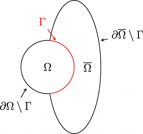
2.27 ) for a simple geometrical set-up, consisting of a circle intersecting an ellipse, see Figure .
For this simple example, we assume that we have tip/tilt measurements available on the circle
, and have to construct
on
. Considering a single layer (
), with the direction
and setting the parameter
, we have, according to (Equation2.23
2.23
2.23 )–(Equation2.28
2.27
2.27 ), to solve the pde system
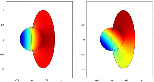
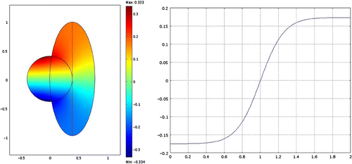
Figure 3. Reconstructed for
(left) and function values of
along a vertical line through the center of the ellipse (right, the line is also depicted in the left image).
where denotes the normal vector to
, and
. As pointed out, we only solve the system for the unit tip/tilt vectors
and
. Figure shows the resulting phase for the vector
. The reconstructed function within the circle (see Figure ) resembles a plane, thus, a tip/tilt. Outside the circle, where no tip/tilt measurements are available, the reconstruction of the tip/tilt in the circle is smoothly extended to the ellipse, see Figure . In Figure , the reconstructions of
for
and
are displayed.
Note that in Figure , the extension of the tip/tilt outside the circle is almost constant, which is due to the fact that the geometry of our example and the chosen tip/tilt measurements allow a smooth continuation. This is, however, not the case for the other examples.
4.2 Reconstruction of a nine-layer atmosphere
We will now present numerical results for a tip/tilt reconstruction using six-laser guide stars and three-tip/tilt sensors.
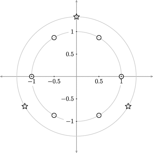
The physical set-up used for our simulations is closely related to the definition of the MAORY system in [Citation31]. The NGS are located on a circle with radius 1.33 arcmin, the LGS on a circle with radius 1 arcmin. The height of the laser guide stars is assumed to be km. For simulation and reconstruction, we use the nine-layer atmosphere defined in Table . The Fried parameter of the atmosphere was set to
m.
Figure shows the positions of the NGS and LGS. In the wavefronts ,
, originating from LGS, the (incorrect) tip/tilt was removed, and the tip/tilt on each layer was reconstructed based on the NGS measurements only. For the reconstruction, we used both the separated (Algorithm 2) and the integrated approach (Algorithm 1).
Table 1. Location of the layers in the atmosphere.
As the tip/tilt reconstruction is needed on each layer, the functions , spanning the range of the operator
, are needed on each layer. As pointed out in Section 2.1, we, therefore, have to evaluate the operators
on the unit vectors
and
. The functions were reconstructed on a square containing the area
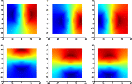
. Figure shows the functions
on layer
only (note that the functions
have a contribution on each layer).
The system of pde’s was solved using a Finite Element method with quadratic ansatz functions. The results have been studied with respect to different choices of the parameter . In Figure and all numerical results below, a value of
10,000 has been used in the computations. Additionally, we would like to remark that the use of the operators
yields a smooth continuation of the tip/tilt reconstruction over the whole square area, including
.
Finally, we compare the performance of the separated approach, the integrated approach and an MVM reconstructor. All simulations and reconstructions have been performed within ESO’s Octopus simulation tool.[Citation32] The used MVM method is an internal Octopus MAP reconstructor, based on a standard (bilinear) discretization. The simulations have been carried out in pseudo-open loop for 500 time steps, which equals a simulation time of 1 s. As time control, a simple integrator has been applied. The Strehl ratio has been used as quality measure (a Strehl ratio equal to 1 resembles the best possible image quality for a telescope with fixed diameter). Figure shows a contour plot of the achievable reconstruction quality over the field of view for the separated as well as the integrated approach.
Figure 7. Contour plot of the Strehl ratio for the integrated (left) and separated (right) approach.
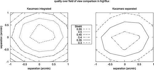
Figure 8. Short and long exposure on-axis Strehl ratios for MVM, separated and integrated reconstructors. The test was carried out with a photon flux of 10,000.
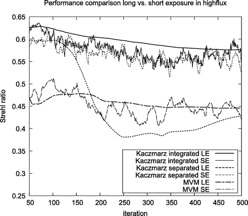
Figure 9. Short and long exposure on-axis Strehl ratios for MVM, separated and integrated reconstructors. The test was carried out with a photon flux of 500.
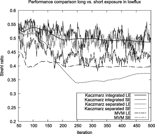
Figure 10. LE Strehl ratios, averaged over the field of view, over photon flux level for MVM, separated and integrated reconstructors.
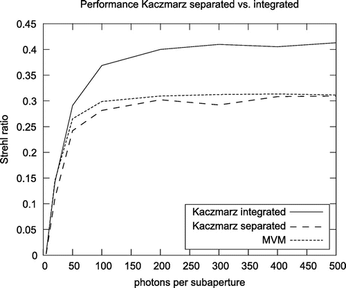
Figures and show the development of the Short- and Long-Exposure (LE) Strehl ratios for the MVM reconstructor as well as the separated and integrated approaches. Both the separated and the integrated approach show a better Short Exposure (SE) Strehl ratio compared to the MVM reconstructor. However, the LE Strehl of the integrated approach is significantly higher than the values for the two other approaches. Additionally, the Short and LE Strehls are close to each other for the integrated approach, which is an indication for a good tip/tilt reconstruction. Note that the LE Strehls of the separated approach and the MVM reconstructor are close to each other. These results are confirmed by Figure , where the LE Strehl, averaged over the field of view, is displayed for different photon flux levels, corresponding to different levels of noise. Again, the integrated approach gives the best results, whereas MVM and the separated approach display comparable results.
One of the main reasons for a new algorithm in adaptive optics is the high computational effort for the standard method. The MVM has a complexity of , where
is the number of subapertures in a Shack–Hartmann wavefront sensor and
is the number of all actuators in the DM. For future big telescopes this number is too high to perform the calculation within the time available.
For the Kaczmarz method, we have to add the complexity of the different steps. The reconstruction of the wavefronts with CuReD can be performed in operations, as stated in [Citation24]. Assuming the use of bilinear ansatz functions on a rectangular grid, a single Kaczmarz iteration has a total number of
operations, with
the number of layers considered. The handling of the tip/tilt indetermination gives another
operations, the additional NGS add
to the total amount. The projection onto the mirrors is done with Kaczmarz iterations as well. This can be performed in
, where
is the number of optimization directions.
For a better understanding, we computed the numbers for the standard setting with six LGS with subapertures (approx. 75% active), three NGS with tip/tilt sensors and three DM with a total of about 9300 actuators. For the MVM, this leads to a computational complexity of
operations. For the Kaczmarz algorithm, we need
operations for the wavefront reconstructions. If the reconstruction is performed on the nine layers of the atmosphere with five iterations, the effort sums up to
operations. In the projection step, 25 optimization directions are assumed. This leads to an additional computational complexity of
operations. Therefore, we can state that the Kaczmarz algorithm is approximately 20 times faster than the MVM algorithm.
Based on our numerical results, we conclude that the integrated approach delivers the best results for the reconstruction of the atmosphere from combined LGS/NGS measurements. The achieved reconstruction quality is even higher than the quality from the standard MVM reconstructor. The separated approach delivers a quality comparable to MVM. As the separated approach is numerically cheaper than the integrated approach, one might consider to use its tip/tilt reconstruction as an initial guess for the integrated approach.
Acknowledgments
This work was supported by the Austrian Ministry of Science within the framework of the ESO Austrian In-kind contribution. Furthermore, the authors would like to thank in particular Stefan Kindermann from Industrial Mathematics Institute, JKU Linz for helpful discussions.
References
- Roddier F. Adaptive optics in astronomy. Cambridge: Cambridge University Press; 1999.
- Roggemann MC, Welsh B. Imaging through turbulence, CRC Press laser and optical science and technology series. Boca Raton (FL): CRC Press; 1996.
- Tokovinin A. Adaptive optics tutorial at CTIO; 2001. Available from: http://www.ctio.noao.edu/ atokovin/tutorial/
- Rigaut FJ, Ellerbroek BL, Flicker R. Principles, limitations and performance of multiconjugate adaptive optics. Proc. SPIE. 2000;4007:1022–1031.
- Ellerbroek BL, Vogel CR. Inverse problems in astronomical adaptive optics. Inverse Prob. 2009;25:1–37.
- Puech M, Flores H, Lehnert M, Neichel B, Fusco T, Rosati P, Cuby J-G, Rousset G. Coupling MOAO with integral field spectroscopy: specifications for the VLT and the E-ELT. Mon. Not. R. Astron. Soc. 2008;390:1089–1104.
- Rousset G, Fusco T, Assemat F, Gendron E, Morris T, Robert C, Myers R, Cohen M, Dipper N, Evans C, Gratadour D, Jagourel P, Laporte P, Le Mignant D, Puech M, Schnetler H, Taylor W, Vidal F, Cuby J-G, Lehnert M, Morris S, Parr-Burman P. EAGLE MOAO system conceptual design and related technologies. Society of Photo-Optical Instrumentation Engineers (SPIE) Conference Series, 7736; 2010.
- Ramlau R, Rosensteiner M. An efficient solution to the atmospheric turbulence tomography problem using Kaczmarz iteration. Inverse Prob. 2012;28:085003--085020.
- Helin T, Yudytskiy M. Wavelet methods in multi-conjugate adaptive optics. Inverse Prob. 2013;29:095004--095026.
- Marchetti E, Brast R, Delabre B, Donaldson R, Fedrigo E, Frank C, Hubin N, Kolb J, Linzon J-L, Marchesi M, Oberti S, Reiss R, Santos J, Soenke C, Tordo S, Baruffolo A, Bagnara P, The CAMCAO consortium. On-sky testing of the multi-conjugate adaptive optics demonstrator. The Messenger. 2007;189:8–13.
- Ellerbroek B, Gilles L, Vogel CR. A computationally efficient wavefront reconstructor for simulation or multi-conjugate adaptive optics on giant telescopes. Proc. SPIE. 2002;4839:989–1000.
- Ellerbroek B, Gilles L, Vogel CR. Numerical simulations of multiconjugate adaptive optics wavefront reconstruction on giant telescopes. Appl. Opt. 2003;42:4811–4848.
- Ellerbroek B, Vogel CR. Simulations of closed-loop wavefront reconstruction for multiconjugate adaptive optics on giant telescopes. Proc. SPIE. 2003;5169:206–217.
- Gilles L, Ellebroek BL, Vogel CR. Preconditioned conjugate gradient wave-front reconstructors for multiconjugate adaptive optics. Appl. Opt. 2003;42:5233–5250.
- Gilles L, Ellerbroek B. Split atmospheric tomography using laser and natural guide stars. J. Opt. Soc. Am. 2008;25:2427–2435.
- Gilles L, Ellerbroek B, Vogel CR. Layer-oriented multigrid wavefront reconstruction algorithms for multi-conjugate adaptive optics. Proc. SPIE. 2002;4839:1011–1022.
- Gilles L, Ellerbroek B, Vogel C. A comparison of multigrid V-cycle versus fourier domain preconditioning for laser guide star atmospheric tomography. Adaptive Optics: Analysis and Methods/Computational Optical Sensing and Imaging/Information Photonics/Signal Recovery and Synthesis Topical Meetings on CD-ROM, OSA Technical Digest (CD). Vancouver (BC): Optical Society of America; 2007.
- Tokovinin A, Le Louarn M. Isoplanatism in a multiconjugate adaptive optics system. J. Opt. Soc. Am. A. 2000;17:1819–1827.
- Tokovinin A, Viard E. Limiting precision of tomographic phase estimation. J. Opt. Soc. Am. A. 2001;18:873–882.
- Vogel CR, Yang Q. Fast optimal wavefront reconstruction for multi-conjugate adaptive optics using the Fourier domain preconditioned conjugate gradient algorithm. Opt. Express. 2006;14:7487–7498.
- Yang Q, Vogel CR, Ellerbroek BL. Fourier domain preconditioned conjugate gradient algorithm for atmospheric tomography. Appl. Opt. 2006;45:5281–5293.
- Zhariy M, Neubauer A, Rosensteiner M, Ramlau R. Cumulative wavefront reconstructor for the Shack-Hartman sensor. Inverse Prob. Imaging. 2011;5:893–913.
- Rosensteiner M. Cumulative reconstructor: fast wavefront reconstruction algorithm for Extremely Large Telescopes. J. Opt. Soc. Am. A. 2011;28:2132–2138.
- Rosensteiner M. Wavefront reconstruction for extremely large telescopes via CuRe with domain decomposition. J. Opt. Soc. Am. A. 2012;29:2328–2336.
- Fusco T, Conan J-M, Rousset G, Mugnier LM, Michau V. Optimal wave-front reconstruction strategies for multi conjugate adaptive optics. J. Opt. Soc. Am. A. 2001;18:2527–2538.
- Kaczmarz S. Angenäherte auflösung von systemen linearer gleichungen [Approximate solution for systems of linear equations]. Bulletin III. A. 1937;35:355–357.
- Kowar R, Scherzer O. Convergence analysis of a Landweber-Kaczmarz method for solving nonlinear ill-posed equations, Ill posed and inverse problems (book series). 2002;23:69–90.
- Haltmeier M, Leitao A, Scherzer O. Kaczmarz methods for regularizing nonlinear ill-posed equations i: Convergence analysis. Inverse Prob. Imaging. 2007;1:289–298.
- De Cezaro A, Haltmeier M, Leito A, Scherzer O. On Steepest-Descent-Kaczmarz methods for regularizing systems of nonlinear ill-posed equations. Appl. Math. Comput. 2008;202:596–607.
- Baumeister J, Kaltenbacher B, Leito A. On Levenberg-Marquardt-Kaczmarz methods for regularizing systems of nonlinear ill-posed equations. Inverse Prob. Imaging. 2010;4:335–350.
- Diolaiti E, Baruffolo A, Bellazzini M, Biliotti V, Bregoli G, Butler C, Ciliegi P, Conan J-M, Cosentino G, D’Odorico S, Delabre B, Foppiani H, Fusco T, Hubin N, Lombini M, Marchetti E, Meimon S, Petit C, Robert C, Rossettini P, Schreiber L, Tomelleri R. MAORY: a multi-conjugate adaptive optics relay for the E-ELT. Messenger. 2010;140:28–29.
- Louarn ML, Verinaud C, Korkiakoski V, Hubin N, Marchetti E. Adaptive optics simulations for the European Extremely Large Telescope – art. no. 627234. Adv. Adaptive Opt. II, Prs 1–3. 2006;6272:U1048–U1056.

