
 ?Mathematical formulae have been encoded as MathML and are displayed in this HTML version using MathJax in order to improve their display. Uncheck the box to turn MathJax off. This feature requires Javascript. Click on a formula to zoom.
Abstract
This paper introduces a general inversion method to simultaneously reconstruct scatterers with different boundary conditions such as Dirichlet, Neumann, Robin, and transmission boundaries without a priori information on their locations, shapes, or physical properties. The forward scattering of mixed scatterers is modeled by a unified framework of T-matrix method, while the objective function considered in the inverse problem is solved by a subspace-based optimization method. The unknowns are T-matrix coefficients, from which the types of boundary conditions of scatterers are identified. Numerical examples show that this method is able to recover not only the shapes of scatterers but also their physical properties and parameters.
1 Introduction
Inverse scattering is a kind of widely used technique to determine characteristics of scatterers such as their locations, shapes and material properties from measured scattered field. Various inverse scattering methods [Citation1–Citation4] have been proposed and widely applied in geological exploration, through wall imaging and remote sensing et al. To the best of our knowledge, most known inverse scattering methods are designed with particular prior information on physical properties of the unknown scatterers. For example, the scatterer should be known as dielectric medium [Citation5–Citation7] or perfect electric conductor (PEC) a priori.[Citation8–Citation11] However, in practical problems, the individual targets to be reconstructed are possible to have different boundary conditions (BCs) simultaneously such as Dirichlet, transmission or Robin et al. This is one of the main motivations of the current study.
It should be indicated that there are already some qualitative inverse scattering methods like linear sampling method [Citation12, Citation13] that can retrieve shapes of scatterers with mixed BCs. However, this qualitative method can not further classify the physical characteristics of scatterers. Therefore, there is a demand to develop a quantitative method to solve such problems. It is well known that this is a challenging task. There are two main difficulties to be overcome, i.e. finding a uniform framework to model the scattering phenomenon of different types of scatterers and developing criteria to further classify their physical properties.
For this aim, recently, we have introduced a T-matrix method [Citation14] to simultaneously retrieve dielectric and PEC scatterers without any prior information. The T-matrix method is a conventional method to solve scattering problems. It was firstly introduced by Waterman [Citation15] and further developed by Chew and Wang [Citation16], Otto and Chew [Citation17, Citation18], Lin and Chew [Citation19]. Before,[Citation14] the original T-matrix inversion method was thought to work with a known boundary type of scatterers. In T-matrix method, scatterers are firstly divided into a set of subunits. Then both the incident and scattered fields are expanded on each subunit as functions of multipoles. The coefficients of scattered field are related to that of the incident field through T-matrix which is determined from BCs. Different properties of scatterers own different T-matrices.[Citation20] This property makes the T-matrix method become a good candidate to model scattering phenomenon of mixed boundary scatterers.
In [Citation14], both monopole and dipole terms were employed in the multipole expansion but only the monopole term exists in most original T-matrix inversions. This is because there exists magnitude difference between dielectric and PEC T-matrix coefficients. Therefore, it can ensure the accuracy of dielectric-PEC mixed boundaries scattering. The PEC was differentiated from dielectric scatterers by the recovered zeroth-order T-matrix coefficient, i.e. the coefficient of monopole term. It has been shown that this classification criterion works well to distinguish dielectric scatterers (even lossy) from PEC.
In this paper, we further extend our work in [Citation14] to a more general case. Four types of BCs including Dirichlet, Neumann, impedance and transmission boundaries are considered simultaneously. It covers most commonly used BCs in electromagnetic or acoustic wave scattering problems. To the best of authors’ knowledge, this is the first paper to discuss a quantitative inversion method to retrieve scatterers with four types of BCs. The scattering phenomenon of mixed boundary scatterers is still modeled in a T-matrix framework. The boundary types of recovered scatterers can be classified according to the different characteristics of T-matrix coefficients. Compared with [Citation14], the problem considered in this paper is more challenging and complicated for the following two reasons: (1) Obviously it is much more difficult to classify four boundary conditions than two; (2) Some boundary conditions exhibit similarities under certain conditions. For example, scatterer with impedance boundary can only be conditionally differentiated from that with Dirichlet or Neumann boundary due to their close relation on physical properties. New classification criterion should be provided to do so. Finally, as seen, T-matrix method is a pixel based inversion method. We will discuss about the uniqueness of T-matrix method for recovering the scatterers with mixed boundaries.
The structure of this paper is as follows. In Section 2, the forward scattering model with T-matrix method is introduced. Then the inverse scattering method based on subspace based optimization is discussed in Section 3. Numerical examples are shown in Section 4. Finally, conclusions are made in Section 5.
2 The forward scattering problem and T-matrix method
2.1 The governing equations of forward scattering problem
The forward scattering problem aims to solve the scattered field due to presence of scatterers illuminated by a sequence of incident waves. In this paper, we consider only two dimensional scattering problems. The domain of interest is supposed to be bounded, where nonmagnetic scatters with different types of BCs are inside, as shown in Figure . Suppose there are a total of
plane waves at a single frequency (wavenumber is
) illuminated evenly from transmitters (Tx) outside
. For each incidence, the scattered fields are measured by
receivers (Rx) located at
as depicted in Figure .
We first briefly introduce the governing equations of two dimensional forward scattering problem with different BCs. For a given incidence, the total field outside scatterers satisfies
1
1 where
is the wavenumber of incident wave in the background medium,
is the wavelength of incident wave and
is the total boundary of all scatterers.
Figure 1. Sketch of scattering problem with mixed boundary conditions.
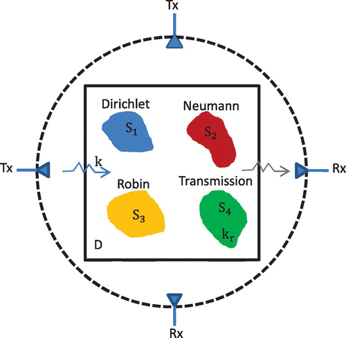
The scattered field can be determined once we know the BCs which reflect intrinsic characteristics of scatterers. Four kinds of BCs, namely, Dirichlet, Neumann, Robin and transmission conditions will be considered simultaneously. In electromagnetics, they correspond to PEC, PMC, impedance and dielectric scatterers, respectively. While in acoustics, they correspond to sound soft, sound hard, impedance and transmission scatterers.
Take the four scatterers in Figure for example. The first scatterer owns Dirichlet BC that satisfies2
2 The second scatterer satisfies Neumann BC
3
3 where
is the normal direction of the scatterer boundary.
The third one satisfies Robin BC4
4 where
is the impedance.
The fourth scatterer has transmission BC that is5
5 For electromagnetic waves with transverse (with respect to the z-axis) magnetic (
) polarization,
is equal to
For acoustic wave,
can be other values. For the transmission BC, the total field inside scatterer satisfies
6
6 where
is the wavenumber inside the scatterer.
2.2 The T-matrix method of forward scattering problem
In this section, we briefly introduce the T-matrix method to solve the governing equations in Section 2.1. More details about T-matrix method can be found in [Citation14] and references therein.
For a single small scatterer, the T-matrix relates the multipole expansion coefficients of the incident field to those of its scattered field. Suppose there is a standalone cylindrical scatterer whose center is located at and its
th order T-matrix is given as
with
as the truncation number of multipoles. Suppose the observation point is at
under the global coordinate. The cylindrical scatterer is illuminated by an incident field, which can be represented by the multipole expansion as
, where
is under the local coordinate of the current scatterer at
. Here
indicates the regular part of Hankel function and
.
is the multiple expansion coefficients of the incident filed. For a plane wave,
has explicit form which can be found in [Citation14, Citation21]. Both the vectors
and
have dimension
. According to the definition of T-matrix, the scattered field can be written by
. The examples of calculating the
will be introduced in Section 2.3.
Next, we derive the scattering equation using the T-matrix representation for general scatterers. Suppose the domain of interest is discretized into
subunits and each subunit is small enough which can be well approximated by a circle of the same area. And the center of each circle is at
under the global coordinate. The field at
(also under a global coordinate) outside all scatterers can be represented by the multipole expansion and addition theorem as [Citation21]
7
7 where the first term of right hand side is the incident field on the
th subunit and the second term is the scattered field from all the subunits. Here
is under the local coordinate of the
th subunit. The vectors
also have a dimension
and they are referred as the vectors of amplitude of the induced multipoles.
The total incident field on the th subunit can be further expressed as the summation of the background incident field and the multiple scattered fields from other subunits. Therefore, we can split Equation (Equation7
7
7 ) into the total incident field (the first two terms in Equation (Equation8
8
8 )) onto the
th subunit and the scattered field off it
8
8 As known, the translational addition theorem enables one to represent the scattered field from other scatterers as a form of the incident field to one scatterer. Namely, there is
9
9 where
is the translational matrix given in [Citation22]. The substitution of Equation (Equation9
9
9 ) into Equation (Equation8
8
8 ) yields
10
10 The first term in Equation (Equation10
10
10 ) means the total incident field on the
th subunit and the second term means the scattered field off it. Thus, from the definition of the T-matrix, we easily obtain,
11
11 Combining Equation (Equation11
11
11 ) on all subunits into one matrix equation, we have
12
12 where
and zero off-diagonal,
for
and zero otherwise,
and
The scattered field at the receiver position
under global coordinate can be obtained by
13
13 where
with
, and
is the local-coordinate representation of the receiver where the origin of the coordinate system is placed at the center of the
th subunit.
Combining the equations for all the receivers into one matrix equation, we have
14
14 Equations (Equation12
12
12 ) and (Equation14
14
14 ) are referred to as the state equation and the field equation, respectively. For each incident field, the two unknowns
and
can be obtained by solving these two equations together. Then all scattered fields
are measured and will be used in inversion.
2.3 The T-matrix coefficients and their asymptotic properties at 
As known, the T-matrix coefficients are determined from boundary conditions. We briefly introduce the derivations here for the easy understanding of readers. For more details, please refer to [Citation20] and references therein. All the derivations are under assumption that the scatterer is circular and homogeneous. Suppose the radius of circular scatterer is .
First the plane wave can be represented as
15
15 The outgoing wave
needs to satisfy the radiation condition at infinity and therefore can be represented as
16
16 Inside the scatterer, the field
should be bounded at
and it is expanded as
17
17 By substituting the above filed expansions into boundary conditions (Equation2
2
2 ), (Equation3
3
3 ), (Equation4
4
4 ) and (Equation5
5
5 ) at
, the corresponding T-matrix coefficients
are obtained. It should be indicated that
is not required in the Dirichlet and Impedance boundary conditions. For these two boundary conditions, the total field is
.
Therefore, the th order of T-matrix coefficients for Dirichlet BC in Equation (Equation2
2
2 ) is
18
18 The
th order of T-matrix coefficients of Neumann BC in Equation (Equation3
3
3 ) is
19
19 The
th order of T-matrix coefficients of Robin BC in Equation (Equation4
4
4 ) is
20
20 It can be noticed that the coefficients of T-matrix for scatterers with Dirichlet and Neumann BCs can also be obtained form Equation (Equation20
20
20 ) by taking
and
, respectively.
Finally, the th order of T-matrix coefficients of scatterer with transmission BC in Equation (Equation5
5
5 ) is
21
21 The T-matrix coefficient in Equation (Equation21
21
21 ) is consistent with the results in [Citation14] where
and
with
as the relative permittivity of scatterer.
Practical scatterers with arbitrary shape and inhomogeneous physical parameters need to be discretized into several subunits which are small enough. Therefore, each subunit is assumed to be homogeneous and can be approximated by an equivalent circular subunit with radius . Then the T-matrix coefficients derived above for circular scatterer can be used as a good approximation.
Table 1. The asymptotic expansions of for small
.
Because each subunit is small enough to ensure the validity of the T-matrix coefficients, it is necessary to understand the asymptotic property of when
is small enough. Under the assumption that
approaches to zero, the asymptotic expansions of
for different types of scatterers are summarized in Table .
3 Inversion algorithm
In this section, we first introduce the inversion algorithm with a subspace based optimization (SOM).[Citation7] Then the criterion to classify different BCs is discussed.
3.1 Subspace based optimization
Suppose the singular value decomposition of is
Therefore, for one incident field, the vector
can be represented by
22
22 where
and
is composed by the rest (excluding the first
) of right singular vectors. Here the value of
can be chosen according to the rules given in [Citation7, Citation23].
For one incident field, the cost functional is built according to (Equation1212
12 ) and (Equation14
14
14 ) as
23
23 The unknowns are the multipole expansion coefficient
and T-matrix coefficients
.
The cost functional (Equation2323
23 ) is reformulated under the framework of subspace optimization method which is found to significantly speed up the convergence and make the algorithm perform robustly in the presence of noise.[Citation5–Citation7] So we have
24
24 where
and
When all incidences are considered, the total cost function can be written as
25
25 The variables
and
in Equation (Equation25
25
25 ) can be updated alternatively during the optimization process.
Before next step, we want to clarify some concerns about the uniqueness of T-matrix inversion for scatterers with mixed boundaries. It is known that the uniqueness of inverse scattering problem for a single type boundary condition has been well established by mathematicians.[Citation24] However, to the best knowledge of the authors, there is little information known for retrieving scatterers with four different boundary conditions simultaneously. And this is out of the scope of our paper to theoretically prove its uniqueness. Since the T-matrix coefficient of a given scatterer, regardless of boundary condition, is unique, we simply suppose here that the T-matrix solution for mixed type inverse scattering problem is also unique. Therefore, we will mainly focus on the numerical discussion about the capability of T-matrix method to solve such problems.
After obtaining the T-matrix coefficients by optimization, we can further determine other parameters of scatterers. For scatterer with Robin BC, the impedance can be further obtained as
26
26 For scatterer with transmission boundary, the recovered wavenumber of scatterer can be obtained as
27
27 For electromagnetic scattering problem, the relative permittivity of dielectric scatterer can be further obtained from Equation (Equation27
27
27 ) as
28
28 After getting the T-matrix coefficients
and other related parameters, the next task is to classify the types of scatterers which is introduced in next section.
3.2 The criterion to classify different scatterers
In this section, we introduce the criterion to classify different scatterers. Theoretically, both and
can be used in the classification. However, the magnitude of
is usually much smaller than that of
and it leads to the inaccuracy of the recovered
. Therefore, in this paper, only
and its related variables
are used in the classification criterion. Here
means related parameter derived from
For example,
can be
or
.
Before we introduce the exact classification criterion, some assumptions and hints are given first:
| (1) | It is known that the Dirichlet and Neumann BCs have close relation to Robin boundary if | ||||
| (2) | In this paper, we only consider the case of | ||||
| (3) | The order of | ||||
| (4) | For the purpose of proving the concept, here we only consider the case of | ||||
Table 2. The order and sign of asymptotic expressions of when
is small.
Table 3. The characteristics of impedance and permittivity obtained from for different scatterers when
is small.
Based on the asymptotic expressions of in Table , their orders and signs are listed in Table . The characteristics of
(by (Equation26
26
26 )) and
(by (Equation28
28
28 )) are listed in Table . The classification criterion for different scatterers are summarized as follows based on information from Tables and :
| (1) | Classify the imaginary part of | ||||
| (2) | The rest pixels with | ||||
| (3) | For the remaining pixels with | ||||
4 Numerical simulations
In this section, the proposed method is tested through a lot of numerical examples. Firstly, the experimental configuration is introduced. The wavenumber of incident wave in background medium is It means the wavelength of incident wave in background medium is
. The domain of interest for all the numerical examples is square of size
. The domain is discretized into
square subunits by default unless other declaration.
plane incident waves are used to evenly illuminate the domain around a circle.
receivers are symmetrically placed around a circle of radius
. The synthetic data is calculated by T-matrix method with
and
additive Gaussian white noise is contaminated in the scattered field. In the inverse problem,
is chosen as the truncation number of the multipoles. The results of
(only monopole) is chosen to compute initial guess. The iteration steps with
is
, while that for
(both monopole and dipole) is 200.
Four examples will be tested by the T-matrix method. There is no prior information about the number and physical characteristics of all the scatterers. As discussed before, exact as well as the reconstructed
,
and
(hereafter the ‘tilde’ symbol indicates the reconstructed value) will be plotted for each example.
4.1 Example 1
The first example is introduced to verify the validity of the proposed T-matrix method and show its resolution with complicated scatterers.
The scatterers are supposed to compose an Austria-like profile. Two circles and one ring are considered simultaneously. The two circles are of radius and their center locations are at
and
, respectively. The center of the ring is at
. Its inner radius is
and its outer radius is
. The left circle has Dirichlet boundary, while the right circle has Neumann boundary. The ring has transmission boundary with
.
We have run this example with and
, respectively. Firstly, the reconstructed results of Example 1 with
are shown in Figure . As discussed before, the key point to classify scatterers with mixed BCs lies in the accuracy of the recovered
because the other two variables
and
are both obtained from
. From Figure , it can be seen that both the real and imaginary parts of
are well reconstructed. Then according to the criterion introduced in Section 3.2, we firstly identify the dielectric scatterer by the imaginary part of
. It can be seen that the ring is a dielectric scatterer with transmission boundary condition and the relative permittivity is approximate to be 2. Since the imaginary parts of the other two circular scatterers are negative, they are classified as Dirichlet, Neumann or Robin boundary. Then based on the results that the
and
are close to zero, it is concluded that the right small circle is a Neumann-boundary like scatterer. Finally, the left small circle is most possibly to be a Dirichlet-boundary like scatterer because its reconstructed
is positive and large.
Furthermore, we run this example again with dense grid at . This is to verify the accuracy of the above results, for both the synthetic measurements and the inversion results of T-matrix method at
. It is noted that synthetic measurements obtained at
are quite similar as that at
. The average relative error (
) between them is
which is quite small and therefore we take
as default discretization number. Correspondingly, the inversion results obtained at
are shown in Figure . It can be seen the results are quite similar as that obtained at
. All scatterers are clearly reconstructed and classified. It should be noted that the T-matrix values are dependent on the circular size, which is controlled by discretization size and therefore are different from Figure .
Figure 2. Inversion results of Example 1 () with
Gaussian white noise. (a) Exact real part of
; (b) Reconstructed real part of
; (c) Reconstructed relative permittivity
; (d) Exact imaginary part of
; (e) Reconstructed imaginary part of
; (f) Reconstructed impedance
.
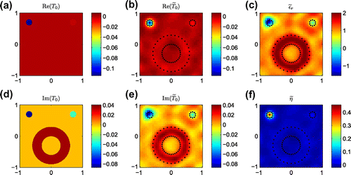
Figure 3. Inversion results of Example 1 () with
Gaussian white noise. (a) Exact real part of
; (b) Reconstructed real part of
; (c) Reconstructed relative permittivity
; (d) Exact imaginary part of
; (e) Reconstructed imaginary part of
; (f) Reconstructed impedance
.
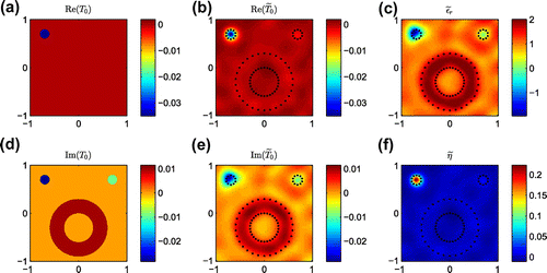
Both the results of Example 1 with different grid sizes show that the T-matrix method own good resolution to recover scatterers with complex shapes and mixed boundary conditions. Since the grid size at is small enough, we will test all the other examples hereafter with this grid configuration.
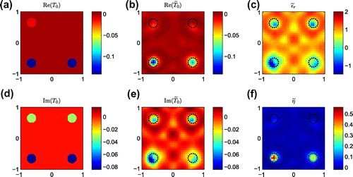
4.2 Example 2
The second example is to further test the robustness of T-matrix method to retrieve scatterers with complicated shapes. There are three scatterers, i.e. two circles together with one rectangle. The two circles are of radius and their center locations are at
and
, respectively. The center of the rectangle is at
with width as
and height as
The upper left circle has Dirichlet boundary, while the upper right circle owns Neumann boundary. The rectangle has transmission boundary with
. The distances between all scatterers are much closer than Example 1 and therefore is thought more difficult to solve.
Figure 4. Inversion results of Example 2 with Gaussian white noise. (a) Exact real part of
; (b) Reconstructed real part of
; (c) Reconstructed relative permittivity
; (d) Exact imaginary part of
; (e) Reconstructed imaginary part of
; (f) Reconstructed impedance
.
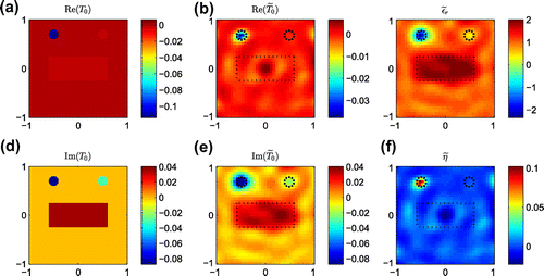
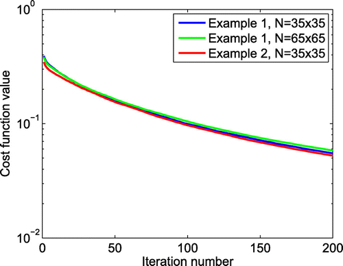
Figure 5. Convergence curves of Examples and
with
.
The reconstructed results of this example are shown in Figure . From the recovered real and imaginary parts of as well as the
, it can be seen the rectangle has transmission boundary condition and the relative permittivity is approximate to be 2. Furthermore, similar as Example 1, the left circle is a Dirichlet-boundary like scatterer and the right circle is a Neumann-boundary like scatterer. Finally, the convergence curves of the first two examples are shown in Figure . It can be seen the T-matrix method converges smoothly to its final solutions. This example further shows that the proposed T-matrix method is stable to retrieve mixed-type scatterers with complex shapes.
4.3 Example 3
The third example aims to evaluate the capability of the T-matrix method to classify all the four kinds of scatterers.
In this example, there are four circles with equal radius and their centers are located at
,
,
and
, respectively. The center of interested domain is at
The upper left circle is a scatterer with Dirichlet boundary. The upper right one owns Neumann boundary. The lower left one has transmission boundary condition and
The last lower right one has impedance boundary condition and
Figure 6. Inversion results of Example with
Gaussian white noise. (a) Exact real part of
; (b) Reconstructed real part of
; (c) Reconstructed relative permittivity
; (d) Exact imaginary part of
; (e) Reconstructed imaginary part of
; (f) Reconstructed impedance
.
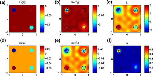
Figure 7. Inversion results of Example with
Gaussian white noise. (a) Exact real part of
; (b) Reconstructed real part of
; (c) Reconstructed relative permittivity
; (d) Exact imaginary part of
; (e) Reconstructed imaginary part of
; (f) Reconstructed impedance
.
The results are shown in Figure . According to the inversion results and the criterion introduced in Section 3.2, we firstly identify the dielectric scatterer by the imaginary part of It can be seen that the lower left circle is dielectric scatterer with transmission boundary condition. Since the imaginary parts of the other three scatterers are negative, they are classified as Dirichlet, Neumann or Robin boundary. From the values of
and
, the boundary condition of the upper right scatterer can be classified as Neumann type. For the left two scatterers, it can be seen their impedances are obviously positive values, especially the upper left one. Therefore, this scatterer is most possibly to satisfy Dirichlet BC, while the lower right one can be Robin BC. As we discussed before, it’s not easy to classify these two kinds of scatterers clearly because the recovered impedance for scatterer with Dirichlet boundary is always finite.
4.4 Example 4
The fourth example is to illustrate the limitation or difficulty of the proposed T-matrix method to classify the Dirichlet or Neumann scatterers with the Robin ones due to their close physical relations.
Suppose there are four circles with the same shapes and locations but different boundary conditions as example 3. The upper left circle has Robin BC and . The upper right one has Neumann BC (
). The lower left one has Dirichlet BC (
). And the fourth one has Robin BC with
Theoretically, the upper two scatterers own similar scattering behavior while the scattered field of the last two scatterers are nearly the same. This is determined by their physical relations and it means that classification of these scatterers with each other is not easy or impossible. The results in Figure verify this conclusion. It can be seen in Figure that the locations and shapes of all scatterers are successfully recovered. And all the four scatterers can be clearly divided into two groups (group 1: the upper two scatterers; group 2: the lower two scatterers) by the values of
and its related
and
. But as expected, it’s difficult to further identify the physical properties of the two scatterers within a group. This is the reason why we add assumption on
for Robin BC in Section 3.2.
5 Conclusions
In this paper, we have introduced a T-matrix method to simultaneously reconstruct the scatterers with different BCs like Dirichlet, Neumann, Robin, and transmission boundaries without any prior information. The numerical results show that the introduced method is a good inversion framework for scatterers with different boundary conditions. The locations and shapes of all scatterers are well reconstructed while their physical characteristics are further classified by the zeroth order coefficients of T-matrix and other related parameters. We also indicate that the current classification criterion still has some limitations for classifying scatterers with similar BCs. This is mainly due to the close physical properties of scatterers. Since both monopole and dipole terms are employed in the current inversion, the computational cost is larger than the conventional method of moment. Further work can be done on accelerating the convergence and reducing the computational cost of the proposed algorithm.
Additional information
Funding
References
- Hansen T, Johansen P. Inversion scheme for monostatic ground penetrating radar that takes into account the planar air-soil interface. IEEE Trans. Geosci. Remote Sensing. 2000;38:496–506.
- Song L, Yu C, Liu Q. Through-wall imaging (TWI) by radar: 2-D tomographic results and analyses. IEEE Trans. Geosci. Remote Sensing. 2005;43:2793–2798.
- Zhdanov M, Hursan G. 3D electromagnetic inversion based on quasi-analytical approximation. Inverse Probl. 2000;16:1297–1322.
- Liu K, Xu Y, Zou J. A parallel radial bisection algorithm for inverse scattering problems. Inverse Probl. Sci. Eng. 2013;21:197–209.
- Zhong Y, Chen X. Twofold subspace-based optimization method for solving inverse scattering problems. Inverse Probl. 2009;25:085003.
- Zhong Y, Chen X, Agarwal K. An improved subspace-based optimization method and its implementation in solving three-dimensional inverse problems. IEEE Trans. Geosci. Remote Sensing. 2010;48:3763–3768.
- Chen X. Subspace-based optimization method for solving inverse-scattering problems. IEEE Trans. Geosci. Remote Sensing. 2010;48:42–49.
- Qing A, Lee CK, Jen L. Electromagnetic inverse scattering of two-dimensional perfectly conducting objects by real-coded genetic algorithm. IEEE Trans. Geosci. Remote Sensing. 2001;39:665–676.
- Qing A. Electromagnetic inverse scattering of multiple two-dimensional perfectly conducting objects by the differential evolution strategy. IEEE Trans. Antennas Propag. 2003;51:1251–1262.
- Ye X, Chen X, Zhong Y, Agarwal K. Subspace-based optimization method for reconstructing perfectly electric conductors Prog. Electromagn. Res. 2010;100:119–128.
- Ye X, Chen X, Zhong Y. Reconstructing perfectly electric conductors by the subspace-based optimization method with continuous variables. Inverse Probl. 2011;27:055011.
- Colton D, Haddar H, Piana M. The linear sampling method in inverse electromagnetic scattering. Inverse Probl. 2003;19:S105.
- Ben Hassen F, Boukari Y, Haddar H. Application of the linear sampling method to identify cracks with impedance boundary conditions. Inverse Probl. Sci. Eng. 2013;21:210–234.
- Ye X, Chen X, Zhong Y, Song R. Simultaneous reconstruction of dielectric and perfectly conducting scatterers via T-matrix method. IEEE Trans. Antennas Propag. 2013;61:3774–3781.
- Waterman PC. Matrix formulation of electromagnetic scattering. Proc. IEEE. 1965;53:805–811.
- Chew WC, Wang YM. A fast algorithm for solution of a scattering problem using a recursive aggregate T matrix method. Microw. Opt. Tech. Lett. 1990;3:164–169.
- Otto GP, Chew WC. Microwave inverse scattering - local shape function imaging for improved resolution of strong scatterers. IEEE Trans. Microw. Theory Tech. 1994;42:137–141.
- Otto GP, Chew WC. Inverse scattering of Hz waves using local shape-function imaging – a T-Matrix formulation. Int. J. Imag. Syst. Tech. 1994;5:22–27.
- Lin JH, Chew WC. BiCG-FFT T-Matrix method for solving for the scattering solution from inhomogeneous bodies. IEEE Trans. Microw. Theory Tech. 1996;44:1150–1155.
- Jones DS. Acoustic and electromagnetic waves. New York (NY): Oxford University Press; 1986.
- Elsherbeni AZ, Kishk AA. Modeling of cylindrical objects by circular dielectric and conducting cylinders. IEEE Trans. Antennas Propag. 1992;40:96–99.
- Chew WC. Waves and fields in inhomogeneous media. 2nd ed. New York (NY): IEEE Press; 1995.
- Oliveri G, Chen X, Zhong Y, Massa A. Multiresolution subspace-based optimization method for inverse scattering problems. J. Opt. Soc. Am. A. 2011;28:2057–2069.
- Colton D, Kress R. Inverse acoustic and electromagnetic scattering theory. 3rd ed. New York (NY): Springer-Verlag; 2013.