 ?Mathematical formulae have been encoded as MathML and are displayed in this HTML version using MathJax in order to improve their display. Uncheck the box to turn MathJax off. This feature requires Javascript. Click on a formula to zoom.
Abstract
A numerical technique to solve the three-dimensional inverse problems that arise in aerodynamic design is presented. The approach, which is well established for compressible flows, is extended to the incompressible case via artificial compressibility preconditioning. The modified system of equations is integrated with a characteristic-based Godunov method. The solution of the inverse problem is given as the steady state of an ideal transient during which the flow field assesses itself to the boundary conditions, which are prescribed as design data, by changing the boundary contour. The main aspects of the Eulerian-Lagrangian numerical procedure are illustrated and the results are validated by comparing with theoretical solutions and experimental results.
1 Introduction
Aerodynamic design consists of finding the most convenient shape for a fluid-immersed body that realizes some expected aerodynamic performances. There is a certain freedom in approaching aerodynamic design. Several routes were exploited in the past by researchers and engineers, with the same goals in mind. The most-followed approach iterates on a sequence of direct analyses. Starting from an initial configuration, the geometry is modified and the aerodynamic effects are either experimentally or numerically evaluated. Thanks to designer experience and intuition this process is driven toward the expected performances. In Computational Fluid Dynamics (CFD), the automation of this approach is known as the classical shape optimization.[Citation1–Citation3] This strategy defines a functional to measure the merit or cost of a certain aerodynamic solution, and a number of geometric control parameters that are used to modify the solution. Then, the functional gradient relative to the controls is evaluated numerically and its information is used to update the control parameters and to march towards the functional extremum. Several methodologies have been proposed in literature to evaluate the functional gradient and also to impose fluid-dynamic and geometrical constraints. Another way of solving the aerodynamic problem is based on the formulation of an inverse problem. In this case, the aerodynamic surface is unknown and some flow features are given on it. The solution of the inverse problem enables designers to obtain the geometry of an aerodynamic device satisfying the governing equations with all the given boundary conditions and other desirable flow constraints. One typical inverse problem is that of finding the airfoil geometry, given the flight speed and the pressure distribution on the profile.[Citation4] The solution of the inverse problem is often a complex task, if compared to the direct analysis approach. Nevertheless, it offers the main advantage of requiring a fewer number of flow-field evaluations to determine the enquired geometry, and also it allows for an easier imposition of the flow constrains (e.g. no flow separation and adverse pressure gradient control [Citation5, Citation6]). Approaches to the inverse problem solution are based on the potential flow theory and conformal mapping techniques,[Citation4, Citation7, Citation8] on stream-function base formulations,[Citation9–Citation11] on boundary elements replacing the body surface [Citation12] and on direct design methods.[Citation13–Citation16] Several examples of inverse problem solution methodologies are presented in [Citation5, Citation17] and references therein.
A generalizable way of solving aerodynamic inverse problems identifies the problem solution as the steady state of an unsteady evolution during which the flow field tries to accommodate itself to the design data, which are prescribed as boundary conditions on the unknown surface.[Citation18] To do this, the surface is allowed to move. To give an idea of the physical scenario involved let us consider, for instance, the design of an airfoil. First, an arbitrary initial geometry is guessed and the related flow field at the selected flight Mach number is evaluated. Then, the target pressure distribution along the profile is imposed. In general, the boundary conditions will not be in agreement with the inner flow field. If we let the profile surface move while it remains impermeable to the flow, walls start moving to decrease the pressure gap. If the system reaches a steady state, and this feature relies on the existence of the steady solution for the Euler equations, then the enquired geometry and the corresponding flow field are found. A similar approach for the determination of the unknown shape is the elastic membrane motion concept [Citation19] or the transpiration velocity.[Citation20–Citation22]
One drawback of inverse problems is that they may be ill posed (according to the Hadamard’s criteria), or they can lead to unacceptable solutions from a designer point of view. If certain wall pressure distributions are required on airfoils, the result is an open or self-intersecting profile. Lighthill discovered the solvability conditions that have to be respected by pressure distributions within an incompressible potential flow model,[Citation4] whereas the conditions for compressible flows and other issues were investigated in [Citation8, Citation23, Citation24] and references therein. The main advantage of numerical optimization over inverse problem is that the first allows the maximization or minimization of global quantities, such as lift or drag, in the presence of constraints, whereas for inverse problems the design is limited to the selection of the pressure or velocity distribution on the boundary,[Citation25] which is given on the basis of designer experience and therefore, somewhat arbitrarily. In addition, a limited control is possible on the final geometry. Optimization techniques based on the adjoint method can be adopted to drive inverse problems towards the maximization or minimization of target functionals.[Citation6] From this point of view, the numerical solution of an inverse problem becomes attractive, as an alternative route to shape optimization and to automated design.
In the present work, a time-dependent technique of solving inverse problems [Citation18, Citation24] is extended to the aerodynamic design in three-dimensional incompressible flows. The numerical method is based on the artificial compressibility approach to make the system of equations virtually hyperbolic.[Citation26, Citation27] The choice of this preconditioning method allows us to easily set up an explicit, Godunov-type numerical scheme [Citation28] and to reuse well-established techniques of solving the compressible Euler and Navier Stokes equations, as well as the related strategies of code optimization and parallelization. Although our investigation has been here limited to inviscid flows, the general methodology has been already extended to viscous flows and validated for the case of two-dimensional and axis-symmetric compressible flows.[Citation29]
The plan of the paper is as follows: the mathematical model and the numerical technique are explained in the context of a characteristic-based finite volume method; then the equation of motion of impermeable surfaces is derived in either cartesian or cylindrical coordinates; finally, some numerical examples are presented and the accuracy of the method is studied through comparisons against theoretical solutions and experimental results.
2 The mathematical model
The pseudo-compressibility method is a preconditioning technique of overcoming the numerical issues related to the uncoupling of pressure and velocity field in the incompressible Euler equations. The governing equations are made artificially hyperbolic by adding a density time-derivative to the continuity equation.[Citation26–Citation28] Based on physical analogies, the time derivative of density is then linked to the pressure by introducing an artificial compressibility factor .
In a Cartesian frame of reference, the system of modified Euler equations is written as1
1 where
2
2 and
3
3 as usual,
is the pressure,
is the velocity vector. All the variables are normalized to the reference length
, density
and pressure
.
The unsteady solutions of system (Equation11
1 ) does not have a physical meaning, but from the numerical point of view, the methods of solution for compressible flow become available. At the steady state, the solution of (Equation1
1
1 ) also satisfies steady Euler equations. The proposed strategy of solving the inverse problem requires the numerical integration of a three-dimensional flow field on a time-dependent domain. Unsteady flow field are solved, in the context of artificial compressibility methods, by introducing a dual time stepping technique.[Citation28] Dual time stepping is here unnecessary, since we are interested in over-relaxing the system to the steady state. Moreover, the time-dependent derivative of the metrics can be neglected without a significant loss of numerical stability.
According to the Gauss formula, an integral form of Equation (Equation11
1 ) is
4
4 where
is the boundary of the volume
and
the outward normal. Equation (Equation4
4
4 ) is approximated using a finite volume technique by discretizing the
space with hexahedral cells whose shape depends on time. The integration in time is carried out according to a Godunov type two-step scheme. A first-order Flux Difference Splitting (FDS) is used at the predictor step: the variables (
,
,
and
) are assumed as an averaged, constant value inside each cell. The fluxes
,
and
are evaluated by solving the Riemann problems pertinent to the discontinuities that take place at the cell interfaces. At the corrector level, the second order of accuracy is achieved by assuming a linear behaviour of the primitive variables inside the cells, according to an essentially non-oscillatory (ENO) procedure.[Citation30] Implicit residual smoothing is applied to increase the numerical stability. The resulting scheme is second-order accurate in space.[Citation28] In next section, we treat extensively the characteristic-based method of imposing the unconventional boundary conditions used to solve the inverse problem. The solution of the Riemann Problem for internal cells and standard boundary conditions is resumed in Appendix 1.
2.1 Dynamics of materially moving boundaries.
Walls on which a flow variable, e.g. the pressure, is imposed, are treated as flexible and impermeable surfaces whose motion is tracked in time until a steady state is reached. In inviscid flows, the velocity vector must be tangent to the wall surface, which is considered a flow surface. It therefore moves materially within the fluid. In this context, the no-through-flow condition represents the kinematic constraint from which the motion of the wall surface is derived.
Let us consider a new Cartesian coordinate system . A generic surface moving in time can be represented, for instance, by equation
. Without any loss of generality, let us assume that
. Thank to the change of variable
, the surface is now defined by the manifold
5
5 This manifold moves materially within the fluid, that is
6
6 and, therefore
7
7 where
is the flow velocity expressed in the
reference system.
In the following, Equation (Equation77
7 ) is coupled to a properly defined Riemann problem. The resulting system is used to compute the fluxes at the boundary and to evaluate the wall velocity. The latter is then integrated in time to find the new wall contour.
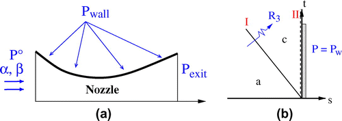
For the inverse problem on a nozzle or diffuser configuration, as shown in Figure (a), the pressure distribution is imposed on the unknown boundary. Aerodynamic devices as wings or blades, instead, are composed by two surfaces that represent a closed contour. In this case, the inverse problem formulation must ensure a correct profile closure and non-overlapping conditions. Among possible approaches, in addition to suitable boundary conditions at infinity, one may:
| (i) | prescribe the distribution of thickness and pressure jump along the chord and enquire for the geometry of the camber line; | ||||
| (ii) | prescribe the distribution of thickness and pressure on one side of the profile and enquire for the geometry of the camber line; | ||||
| (iii) | prescribe the pressure distribution around the profile and enquire for its geometry. | ||||
All of the mentioned cases can be grouped in two approaches in imposing the boundary conditions: the case of a surface on which a pressure distribution is imposed and the case of two aerodynamic surfaces subjected to a prescribed pressure jump. In the following sections, the kinematic constraint (Equation77
7 ) is accomplished to the flow-field boundary conditions in order to derive the fluxes and the velocity on the unknown surfaces.
Figure 1. Inverse problem on a three-dimensional nozzle. (a) Schematic view of the imposed boundary conditions; (b) wave pattern of the Riemann problem at the unknown aerodynamic surface on which the pressure is prescribed.
2.1.1 Boundary condition for moving surfaces with imposed pressure.
Without loss of generality, we consider the aerodynamic design of a subsonic nozzle configuration, as shown in Figure . Being the upper wall, the unknown surface, on it we assign the pressure distribution . On that boundary, an half-Riemann problem has to be solved to derive the fluxes at the cell interface. The resulting wave pattern is shown in Figure (b). The Riemann invariants across fields (a) and (c) are
8
8 where
are the normal, tangent and binormal components of the velocity vector in the local frame of reference on the cell interface. The pressure level of field (c) is assigned as design variable
. The velocity
is deduced from the first of conditions (Equation8
8
8 ) and is given by
9
9 being
the pseudo-velocity of sound.
Once the field (c) is known, the surface velocity is computed from Equation (Equation77
7 ) as
10
10 The same procedure holds for case (ii) with minor modifications. Once either the upper or lower surface of the profile has been selected, fluxes and boundary contour velocity are evaluated by Equations (Equation8
8
8 )–(Equation10
10
10 ) and its shape integrated in time. Concerning the other surface, since Equation (Equation14
14
14 ) holds, at each step the geometry is deduced from the thickness distribution, while the fluxes can be computed using the moving wall boundary condition.
2.1.2 Boundary conditions for inverse problem on surfaces with imposed pressure jump.
In this section, we derive the boundary conditions to solve the inverse problem over three-dimensional profiles according to formulation (i). We consider the design of a stator blade, but the same procedure still holds, with simplifications, for 3D wings. The blade boundary is split into the upper and lower surface and represented by the equations and
in a cylindrical frame of reference
.
The upper and lower
blade surfaces represent two boundaries on which two half-Riemann problems have to be formulated to impose boundary conditions. These Riemann problems are also coupled together by the prescribed pressure jump distribution and by a kinematic condition.
If we ideally cross the blade along the -direction, we can identify states (
) and (
) as the flow conditions close to the lower and upper surfaces (see Figure ). On the lower surface, the Riemann invariants across fields (
) and (
)
(
) are
11
11 On the upper surface, across fields (
) and (
)
(
), we also have
12
12 The wall pressure is constrained, since the pressure jump is a given function
, that is,
13
13 Moreover, since blade thickness is assigned, the velocities of the upper and lower surfaces have to be the same
14
14 To impose this kinematic constraint we have to derive the analogous of Equation (Equation7
7
7 ) in the cylindrical frame, which is
15
15 The Euler equations are integrated using formulation (Equation1
1
1 ), so that the evaluation of the fluxes is done on a Cartesian local frame. Therefore, three reference frames are used:
| (a) | an absolute, Cartesian frame 1 | ||||
| (b) | a local relative frame 2 | ||||
| (c) | a cylindrical frame 3 | ||||
2.2 Remarks on problem well-posedness
One drawback of inverse problems is that they may be ill-posed. While appropriate boundary conditions can be defined easily in the case of the inverse design of channels, a special treatment is required when dealing with more complex aerodynamic surfaces. For instance, if certain wall pressure distributions are required on airfoils, the result is an open or self-intersecting profile. Lighthill discovered the solvability conditions with respect to pressure distributions within an incompressible potential flow model,[Citation4] whereas the similar integral conditions for compressible flows and other issues were investigated in Refs. [Citation8, Citation23, Citation24]. The way of overcoming these issues depends on the strategy used to impose the closure of the body contour. This problem has already investigated in the proposed literature and can be addressed in two ways: one can satisfy the closure conditions or reformulate the inverse problem in order to automatically satisfy such constraints.[Citation24]
As far as the proposed numerical approach is concerned, the problem we formulated to track the unsteady motion of the aerodynamic surface is always well-posed. Nevertheless, if the underlying inverse problem is ill-posed, the procedure simply does not converge to a steady solution. In other cases, the procedure may fail because of lack on problem uniqueness. If more than one solution could be admissible for the same inverse problem, the numerical procedure may be triggered towards one of the possible configurations. Often the problem uniqueness is recovered by changing a boundary condition.[Citation24, Citation29] Finally, we remark that to the hyperbolic Equation (Equation77
7 ) is associated an initial condition
that defines a locus on the unknown aerodynamic surface that does not change during integration. Among the possible choices we selected one of the edges, on that the surface appears to be fastened ‘as a flag’ during its transient motion. For blades, we selected the leading edge locus. Other choices (e.g. the trailing edge locus or a generic 3D stacking line) should be regarded as different initial conditions for the problem that, in general, lead to a different solution. This topic, anyway, belongs to the field of optimal design rather than to the inverse problem solution itself.
3 Numerical results
In next sections, the accuracy of the method is addressed. First, the numerical results of the inverse procedure is validated against two analytical solutions of the Euler equations. Then, accuracy and reliability of the procedure are checked for the more complex case of blade design. The inverse procedure is validated by using numerical results and experimental data (for the E/TU-1 Test Case).
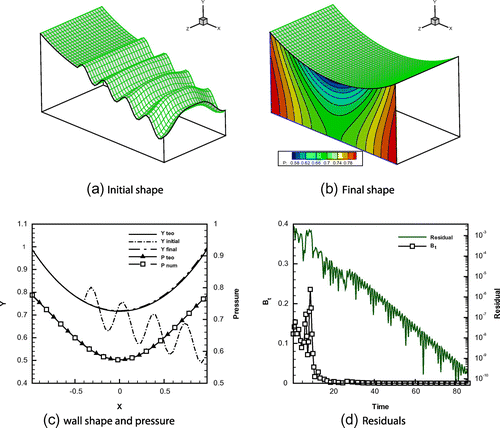
Figure 3. The inverse problem on a three-dimensional nozzle. (a) Initial nozzle geometry with a wavy upper boundary.(b) Final nozzle geometry as computed by the inverse method. A slice with pressure isolines is also depicted. (c) Comparisons of the wall geometry and of the static pressure distributions with the corresponding target analytic values. (d) Time history of the -norm residual and of maximum wall velocity.
3.1 Three-dimensional nozzle
The inverse design of a nozzle has been chosen as test case for the inverse problem formulation described in Section 2.1.1. The pressure distribution imposed on the unknown aerodynamic surface is derived from the potential flow theory. The planar solution is extended in three dimensions by applying periodic boundary conditions in the transversal direction .
A converging–diverging nozzle is obtained from the flow field of a standing vortex on the half plane. The flow can be represented by the complex potential 22
22 where
is the position,
is the asymptotic velocity,
is the vortex strength and
is the distance of the vortex from the
-axis. The two-dimensional nozzle is confined by the streamlines
and
, where
. The velocity field can be deduced from Equation (Equation22
22
22 ) as
23
23 while the pressure field is obtained from Bernoulli equation, once the total pressure level
at inlet is fixed. The numerical test has been performed on a
grid for the case with
,
,
. We also set
. With the scope of generating a fully 3D transient flow, we started from an initial geometry characterized by a wavy upper wall, as shown in figure (a). The theoretical values of total pressure
, the flow angles at inlet
and
, the static pressure distribution at the outlet
and the target static pressure
along the upper wall are imposed as boundary conditions. As final solution, the projection of the upper wall geometry on the
-plane is expected to match the theoretical curve
. Initial and final geometry are shown in Figure (a) and (b). The theoretical solution is obtained with high accuracy. As visible in Figure (c), the computed wall contour and the pressure distribution are almost superposed to the theoretical solution. The convergence history of the
-norm of the shape error and the maximum wall velocity are shown in Figure (d). Since Euler equations do not introduce dissipation or diffusion, the transient depends on how fast the propagating perturbations cancel out due to inertial effects and on how quickly they are absorbed by the flow-field boundaries. The full computation has required an half hour on a 8-core Intel i7 desktop computer.
3.2 Free vortex flow
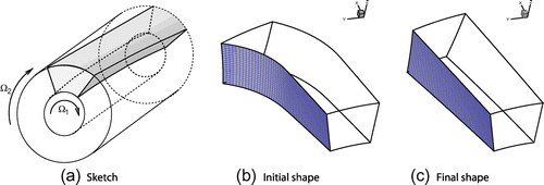
The free vortex flow is a special case of flow in radial equilibrium. [Citation31] This axis-symmetric analytical solution of the Euler equations is used to validate the inverse procedure formulation (i) of Section 2.1.2. The test case is derived from the general solution of the flow field between two rotating cylinders, as depicted if Figure (a). Let us suppose that the inner cylinder rotates with angular velocity , and the outer one with angular velocity
, where
,
are the radii of the inner and outer cylinder, respectively, and
is a given constant. The velocity field is defined as
24
24 where
is also constant. Equation (Equation24
24
24 ) represents an helicoidal motion with translation velocity
, tangential velocity
and angular velocity
. By integration, the flow trajectories can be found as
25
25 with
; in our case it is
26
26 In the numerical test, we tried to find the three-dimensional shape of the stream tube having a sector of circular crown as planar section at
(see the grey zone in Figure (a). The analytical solution of the stream surface can be easily evaluated by using Equation Equation26
26
26 for each point of the stream tube contour at the axial station
. The test follows the footsteps of the previous case. An initial, arbitrary configuration is assumed and the boundary conditions are imposed according to the theoretical solution and to the inverse problem formulation. The total pressure
and the theoretical flow angles are imposed at inlet. At the outlet, the static pressure is given by
27
27 The domain boundaries at the outer and inner radii are treated as solid walls, while the lateral boundaries are the unknown surfaces we aim to resolve. As stream surfaces, they are impermeable, since the velocity vector must be tangent to them. Moreover, they cannot sustain any force, so that the pressure jump across these interfaces is null.
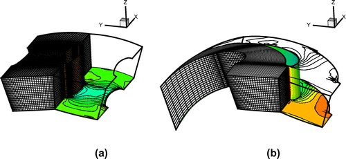
We have recovered the lateral surfaces shape by imposing a zero pressure jump condition and by allowing these boundaries to move according to the dynamic model of Section 2.1.2 until a steady state is reached. In the final configuration, the flow field is expected to coincide with the free vortex solution and the two moving boundaries with the corresponding flow surface, according to Equation (Equation2626
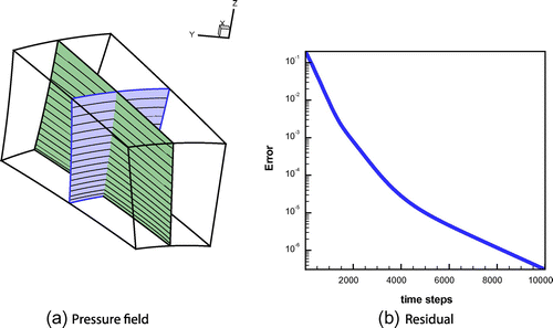
26 ). The initial guess and the final domain shape are shown in Figure . At the steady state, the free vortex flow is obtained and it is presented in Figure(a), where the iso-pressure contours on a longitudinal and a transversal section are shown. The
-norm of the shape error is given in Figure (b). The absolute error is of the order of
.
3.3 Inverse problem on a stator blade
The numerical experiment here proposed is a check of the full correspondence, at the steady state, between the inverse procedure and the direct solver solution on the same geometry. The blade geometry computed by the inverse procedure is introduced in a direct solver and the flow field is computed again, now by using standard boundary conditions. The two solutions are then compared. Arbitrarily, we assumed the following expression for the blade thickness28
28 where
,
are the leading and trailing edge axial stations, respectively, and
is the axial chord. The constants are set to
and
. Similarly, the blade load is prescribed as
29
29 with
. The inlet and outlet boundary conditions are:
,
,
and
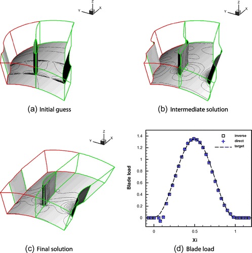
, respectively. Starting from the initial guess of a blade with planar camber line, the transient dynamics of the system is integrated numerically until a steady state is reached. At each step, the blade geometry is recovered from the computed velocity of the blade surface. Only the dynamics of the blade suction side is computed. Pressure-side surface is deduced from the knowledge of thickness. A snapshot sequence of the blade moving surface is depicted in Figure (a–c). The transient resembles the motion of a flag on the wind, fastened on one side. More precisely, the grid describes a sliding motion on the tangential direction, since the axial chord of the blade does not change during the inverse process. At convergence, the blade geometry is found. By switching the code in direct mode, the flow field is computed with standard boundary conditions, and the blade load is evaluated. The solutions of the inverse and direct solver computations are in good agreement. The computed blade load
, in direct and inverse modes and the target
, defined in Equation (Equation29
29
29 ), are compared in Figure (d). A pressure mismatch, with respect to the target blade load distribution of Equation (Equation28
28
28 ), can be observed close to the blade leading edge. This is a well-known local effect caused by the poor resolution properties of the H-type grids close to the leading edge. A finer grid gives a more detailed flow but is meaningless for the test proposed, since the inverse and the direct solvers are acting on the same grid.
Table 1. Main parameters of E/TU-1 test-case.
3.4 E/TU-1 test case
The E/TU-1 test-case [Citation32] focuses on a low speed, low aspect ratio, high turning annular nozzle guide vane (Table ). The blades have a constant profile over the blade height and are untwisted. The severe inlet skew (e.g. at the hub) and the high turning angle (about
) generate a fully three-dimensional flow. We aim to compare a blade geometry computed by the inverse procedure with that given in Ref. [Citation32]. Again, in solving the inverse problem, the formulation (i) is used. The blade thickness distribution was taken from [Citation32], while the blade load has been deduced from the numerical results of Oktay et al. ([Citation33], Figure ).
In the initial geometry the effective thickness distribution has been superposed to a planar camber surface, as shown in Figure (a). A grid refinement study showed that a stretched grid was appropriate for describing the evolution of the computational domain.
Figure 8. The E/TU-1 Test Case. Distribution of the static pressure coefficient along the blade at various radial positions.

Figure 9. The E/TU-1 Test Case. (a) Convergence history of the -norm of the shape error and (b) evolution of the computed blade profile at the midspan (the real geometry is shown as ‘target’) and (c) computed blade profiles at different radii.

The numerical test follows the footsteps of the previous cases. The initial guess and the solution of the inverse problem are shown in Figure . The procedure has converged at slower rate than previous examples. The flow field around the thicker blade with rounded leading and trailing edges is resolved by the H-type grid with lower accuracy. It must be noted that also the target pressure distribution itself was extracted from a numerical simulation affected by the same accuracy problem.
The inverse procedure has required more grid points than Ref. [Citation33] in the stream-wise direction ( nodes instead of
) to ensure an adequate resolution of the blade contour motion. At each time step the mesh was recomputed from scratch, by maintaining the same stretching constants and domain discretization. As far as Euler equations are concerned, the computations remain quite affordable, even by using this rough remeshing approach.
In Figure , the final pressure distribution obtained along the blade is compared with that extracted from Ref. [Citation33]. Although the blade load was enforced in the numerical test, the local pressure distribution is also in fair agreement with the reference data-set. The higher mismatch is observed at the tip radius (Figure ). In that figure, it is also evident that both computations suffer the same discretization problem (a H-type grid is also used in Ref. [Citation33]). Finally, the convergence history and the evolution of the blade geometry are shown in Figure .
4 Conclusions
A numerical method of solving three-dimensional inverse problems in incompressible flows has been presented. Details have been given for the derivation of the inverse problem over configurations of interest in the aerodynamic design as nozzles, diffusers, blades or wings. The numerical method is based on the pseudo-compressibility technique of preconditioning the unsteady Euler equations. Time accuracy is unnecessary, so that dual time stepping and the computation of the time derivatives of the metrics are avoided. Moreover, the characteristic-based formulation of the problem simplifies the parallelization of the code. The accuracy of the numerical procedure has been tested through comparisons with theoretical solutions, numerical computations performed with direct solvers and finally, test against experimental data. Discrepancies at the blade leading edge have been observed, caused by the H-type grid we used. Further extension of the inverse procedure to the Navier-Stokes equations, in a way similar to Ref. [Citation29], is planned. An intermediate step required is the introduction of efficient over-relaxing techniques, to increase the convergence ratio. For the inverse design of aerodynamic profiles, the surface tracking algorithm should be modified to deal with C-type grid generation systems that allow for an accurate evaluation of the viscous stresses.
References
- Pironneau O. On optimum design in fluid mechanics. J. Fluid Mech. 1972;59:117–128.
- Jameson A, Martinelli L, Pierce NA. Optimum aerodynamic design using the Navier-Stokes equations. Theor. Comput. Fluid Dyn. 1998;10:213–237.
- Dennis BH, Han Z-X, Dulikravich GS. Optimization of turbomachinery airfoils with a genetic/sequential quadratic programming algorithm. AIAA J. Propul. Power. 2001;17:1123–28.
- Lighthill JM. A new method of two-dimensional aerodynamic design. Aeronautical Research Council Reports and Memoranda n. 2122; 1945.
- Dulikravich GS, Dennis BH, Baker DP, Orlande HRB, Colaco MJ. Inverse problems in aerodynamics, heat transfer, elasticity and materials design. Int. J. Aero. Space Sci. 2012;13:405–420.
- Iollo A, Ferlauto M, Zannetti L. An aerodynamic optimization method based on the inverse problem adjoint equations. J. Comput. Phys. 2001;173:87–115.
- Mangler W. Die Berechnung eines Tragflügelprofiles mit vorschriebener Drückverteilung [Computation of an aerodynamic profile with a prescribed pressure distribution]. Jahrbuch Deutsches Luftfahrtvorschung. 1938;1:46–53.
- Daripa P. Solvability condition and its application to fast numerical solution of overposed problems in compressible flows. J. Comput. Phys. 1991;95:436–449.
- Zannetti L. A natural formulation for the solution of two-dimensional or axis-symmetric inverse problems. Int. J. Numer. Meth. Eng. 1986;22:451–463.
- Keller JJ. Inverse equations. Phys. Fluids. 1999;11:513–520.
- Scascighini A, Troxler A, Jeltsch R. A numerical method for inverse design based on the inverse Euler equations. Int. J. Numer. Meth. Fluids. 2003;41:339–355.
- Lewis RI. Vortex element methods for fluid dynamic analysis of engineering systems. New York (NY): Cambridge University Press; 1991.
- Taiebi Rahni M, Ghadak F, Ashrafizadeh A. A direct design approach using the Euler equations. Inverse Probl. Sci. Eng. 2008;16:217–231.
- Ashrafizadeh A, Okhovat S, Pourbakian M, Raithby GD. A semi-coupled solution algorithm in aerodynamic inverse shape design. Inverse Probl. Sci. Eng. 2011;19:509–528.
- Qiu X, Ji M, Dang T. Three-dimensional viscous inverse method for axial blade design. Inverse Probl. Sci. Eng. 2009;17:1019–1036.
- van Rooij MPC, Dang TQ, Larosiliere LM. Improving aerodynamic matching using a 3D multistage inverse design method. ASME J. Turbomach. 2007;129:108–118.
- Elizarov AM, Il’innskiy NB, Potashev AV. Mathematical methods of airfoil design. Berlin: Akademie Verlag; 1997.
- Zannetti L. Time dependent method to solve inverse problems for internal flows. AIAA J. 1980;18:754–758.
- Garabedian P, McFadden G. Design of supercritical swept wings. AIAA J. 1982;20:289–291.
- Demeulenaere A, Van den Braembussche R. Three-dimensional inverse method for turbomachinery blading design. ASME J. Turbomach. 1998;120:247–255.
- Demeulenaere A, Van den Braembussche R. A new compressor and turbine blade design method based on 3D Euler computations with moving boundaries. Inverse Probl. Eng. 1999;7:235–266.
- De Vito L, Van den Braembussche R, Deconinck H. A novel two dimensional viscous inverse design method for turbomachinery blading. ASME J. Turbomach. 2003;125:310–316.
- Volpe G. Geometric and surface pressure restrictions in airfoil design. AGARD Report 780; 1990.
- Zannetti L, Larocca F. Inverse methods for 3D internal flows. AGARD Report 780; 1990.
- Dulikravich GS. A criteria for surface pressure specification in aerodynamic shape design. 28th Aerospace Sciences Meeting, AIAA Paper 90–0124; 1990.
- Chorin AJ. A numerical method for solving incompressible viscous flow problems. J. Comput. Phys. 1967;2:12–26.
- Rizzi A, Eriksson LE. Computation of inviscid incompressible flow with rotation. J. Fluid Mech. 1985;153:275–312.
- Drikakis D, Rider W. High-resolution methods for incompressible and low-speed flows (Computational fluid and solid mechanics). Berlin: Springer Verlag; 2005.
- Ferlauto M, Marsilio R. A viscous inverse method for aerodynamic design. Comput. Fluids. 2006;35:304–325.
- Harten A, Engquist B, Osher S. Uniformly high-order accurate essentially non-oscillatory schemes III. J. Comput. Phys. 1987;71:231–303.
- Horlock JH. Axial flow turbines – fluid mechanics and thermodynamics. London: ButterWorths; 1966.
- Sieverding CH. Test case E/TU-1: Low speed annular turbine blade row. AGARD-AR-275. Test-case for Computation of Internal Flows in Aero-Engine Components. Hull: Canada Communication Group; 1990. p. 322–323.
- Oktay E, Akmador S, Ücer A. A numerical solution of 3D inviscid rotational flow in turbines and ducts. Int. J. Numer. Meth. Fluids. 1998;26:907–926.
Appendix 1
Riemann invariants
In order to highlight the wave structure of the system, we switch to the quasi-linear form of equations (Equation11
1 )
A1
A1 where
A2
A2 After integration of Equation (EquationA1
A1
A1 ), according to the Gauss formula, the fluxes are written in the form
A3
A3 where
is the outward normal to the cell surface. As a property of hyperbolic systems, matrix
is decomposed as
A4
A4 where
and
are the matrices of the right and left eigenvectors, respectively, and
is a diagonal matrix that contains the eigenvalues of
A5
A5 where
,
and
are the velocity components in the local frame of reference, and
is the pseudo-velocity of sound. The matrix
is
A6
A6 and, by inversion (
)
A7
A7 The Riemann invariants are obtained by
A8
A8 After algebraic manipulations, the result is
A9
A9
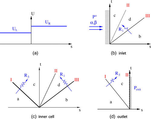
Riemann problem for internal points
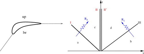
Analysing the wave system depicted in Figure , the following conditions hold across wave system I, between fields (a) and (c),A10
A10 whereas, across wave system III, between fields (b) and (d), we have
A11
A11 Wave system II represents a contact discontinuity, so that
A12
A12 the second relation holds since this surface cannot sustain any force. The solution of system (EquationA10
A10
A10 )–(EquationA12
A12
A12 ) is
A13
A13
A14
A14
A15
A15
A16
A16 where the Riemann invariants of fields (a),(b),(c) and(d) are approximated by
A17
A17
Boundary conditions
Inlet conditions At the inlet, a half-Riemann problem is formulated by replacing the missing signals with an equal number of boundary conditions. Three wave signals are unavailable at inlet, two travelling with velocity and one travelling with velocity
(see Figure (b)). The former wave conveys signals
and
, here replaced by imposing the flow angles
and
. The signal conveyed along
is replaced by the condition of constant inlet total pressure
.
Outlet Conditions In subsonic flows, is always negative. The signal that travels along the characteristic with slope
is missing at the outlet (see Figure (d)) and is replaced by the boundary condition
.
Wall Boundary Condition In inviscid flows, the no-through-flow condition is imposed at wall. When the wall is fixed, the wave configuration is represented by the scheme shown in Figure (d), where wave II is now travelling with velocity at the boundary. The characteristic with slope
is missing, so that one boundary condition is required, this is written as
. If the wall is moving with velocity
, the above-mentioned conditions hold in the relative motion.

