 ?Mathematical formulae have been encoded as MathML and are displayed in this HTML version using MathJax in order to improve their display. Uncheck the box to turn MathJax off. This feature requires Javascript. Click on a formula to zoom.
Abstract
Inverse shape design in the context of fluid flow problems is commonly referred to the determination of the boundary shape corresponding to a given target surface pressure. Designers naturally turn to this class of problems whenever there are concerns regarding pressure-related phenomena such as cavitation, separation, shock waves, surface loading, etc. Numerical solution is often unavoidable and, therefore, three computational tools, i.e. a grid generator, a flow field solver and a shape updater, are required in an iterative solution procedure. In all existing iterative inverse design methods, the shape updater comes from separate mathematical or physical considerations that are not derived solely from the equations governing the flow field. In this paper, the currently used strategies to solve inverse shape design problems are categorized and reviewed, and then a truly physical-based iterative inverse shape design method is introduced in which the governing equations are not only used in the flow solver, but are also employed to update the shape. To explore the features of the proposed method, it is used to solve a number of shape design problems. The previously developed direct shape design method and a typical iterative solution approach are also explained and used for the solution of the same problems for the purpose of comparison. Computational results reveal that the proposed algorithm has a two to three times faster convergence rate as compared to the iterative algorithm. The convergence rate of the proposed algorithm usually stalls after three or two orders of magnitude reduction of the residual. For the test cases in this study, the direct design method is the fastest and most accurate method as compared to other algorithms. Both in-house developed computer codes and commercial software are used as a field solver to show the general applicability of the proposed method in its current state of development.
1. Introduction
Governing equations in most of thermo-fluid engineering problems are differential equations. Solution of such problems, therefore, requires information regarding the size and shape of the solution domain, thermo-physical properties of the fluid and some auxiliary conditions, i.e. boundary and initial conditions. If some of the information necessary to analyse a thermo-fluid problem is missing, the problem is generally called a design or inverse problem.[Citation1] To compensate the missing information and render the design problem, well-defined, additional constraints are needed. In the fluid flow context, when part of the boundary shape is not known but the expected pressure distribution at that part of the boundary is given, the design problem is called a surface shape design (SSD) problem.[Citation2] Nearly, in all practical situations, analytical solution of analysis and design thermo-fluid problems, including SSD problems, is not a choice and numerical solution is unavoidable.
Iterative solution strategies for SSD problems start with an initial guess for the shape and use the target surface pressure to drive the current shape to the desired shape corresponding to the given target pressure. To carry out such calculations, three main computational tools are needed. The required tools include a grid generator, to discretize the solution domain, a flow solver, to update the state variables, and a shape updater, to modify the boundary shape using both the target pressure and the most recent available data on the surface pressure. SSD algorithms differ according to the methods employed and sequences carried out to update the shape, grid and state of the flow field. One useful categorization suggests three families of methods: fully coupled, semi-coupled and uncoupled solution techniques.[Citation3] In what follows a brief review of the research regarding the solution of SSD problems in the context of the above-mentioned categorization is provided.
Uncoupled algorithms are the oldest, and most commonly used, methods in which the updates of the shape, grid and flow are carried out separately and sequentially. The solution procedure starts with an initially guessed shape. After generating the computational grid, the flow solver is called to update the state and to calculate the current surface pressure distribution. The shape updater is then employed to provide a new boundary shape, supposedly closer to the final desired shape. With the new shape available, the grid generator is called again and the computational steps are repeated until the target pressure is achieved within an acceptable tolerance.
The uncoupled algorithms differ mainly due to the shape update strategy employed. In mathematical-based uncoupled SSD algorithms, commonly called optimization methods, the difference between the target and current pressure distribution is defined as an objective function and the minimum of this function is sought using the ideas routed in calculus. In physical-based uncoupled SSD algorithms, assumptions are made and physical analogies are employed to guide the shape evolution during iterations.
Gradient-based optimization methods [Citation4–7] generate and use the information regarding the objective function gradients to specify the search direction and step size in that direction in the design space. Evolutionary methods [Citation8–11] find the optimum solution based on repeated function evaluations. Optimization methods, in general, are computationally expensive and rather mathematically complex. However, they can be used to minimise different objective functions while satisfying various constraints on design variables. In other words, solution of SSD problems, which corresponds to minimising the difference between the current and target surface pressures, is just one of the applications of the optimization methods and these methods are quite flexible and generally applicable in various design problems.
Physical-based uncoupled SSD algorithms are rather mathematically simple. One way or another, often a linear relation is established between the boundary node displacement (∆ri) and the local surface pressure mismatch (∆pi) to update the shape.
In the so-called wall transpiration models [Citation12–15], the pressure mismatch between the current and target pressure results in mass leakage from the boundary, and the boundary shape is changed iteratively until the continuity is satisfied and normal velocity components at the wall are annihilated. In the flexible string algorithm, proposed by Nili-Ahmadabadi et al. [Citation16–18], the boundary is considered as an elastic string that deforms under the force due to the pressure mismatch. In another method, called the ball-spine Algorithm,[Citation19–22] hypothetical balls are distributed along the boundary. These balls are allowed to move along specified directions, called spines, under the pressure mismatch force. Starting from an initial boundary shape, balls are displaced until the target pressure at the boundary is satisfied.
Residual-correction methods have also been developed by researchers to solve the SSD problem. Barger and Brooks [Citation23] relate the boundary curvature to the tangential velocity mismatch at the boundary in the context of inviscid flow. Similar ideas have been followed by other researchers.[Citation24–26] Garabedian and McFadden [Citation27] have proposed a residual-correction method, the GM method, to design part of the geometry of a transonic airfoil. Malone et al. [Citation28] developed a modified version of the GM method, the MGM method, that overcomes some of the limitations of the GM method. This modified GM method has been used in the context of full-potential [Citation29], Euler [Citation30] and Navier–Stokes [Citation31,32] flow models. However, the MGM methods suffer from at least two important shortcomings. First, the local convergence rate in some locations, for example, near the leading and trailing edges of an airfoil, is very slow, and second, the convergence rate is deteriorated when the nonlinearity of the problem increases. It is important to mention that in airfoil design via the MGM method, the Navier–Stokes solver is called about 10,000 times and any improvement in the convergence rate saves a lot of time. Dulikravich and Baker [Citation33] have proposed a method using elastic membranes that increases the convergence rate of the modified GM methods considerably.
It is seen that in the currently used uncoupled SSD solution methods, separate mathematical or physical arguments are used to update the shape. A rather general drawback in all of these methods is the need to employ physical analogies or to use and tune some coefficients mostly on an ad hoc basis. However, any flow solver, including commercial and open source software, can be employed in the uncoupled solution algorithms and this is a major advantage.
In fully coupled algorithms, the governing equations are reformulated such that the shape, computational grid and the fluid state are all updated simultaneously. Initially, these algorithms were applicable only in the context of simple flow models. For example, Stanitz [Citation34] formulated the SSD problem in the context of incompressible, inviscid (ideal) flow in terms of secondary variables, i.e. stream and scalar potential functions. Using this formulation, a target surface tangential velocity distribution can be specified in the computational domain to directly obtain the corresponding boundary shape. Zannetti [Citation35] proposed a similar formulation in the context of Euler equations to design two-dimensional axisymmetric channels. Chaviaropoulos et al. [Citation36,37] formulated a fully coupled three-dimensional SSD problem in the context of potential flow. They showed that the use of scalar potential in this formulation results in an ill-posed problem with multiple solutions. More recently, Borges [Citation38] has suggested another fully coupled formulation of the SSD problem in the context of ideal flow in which the transformed governing equations are linear, but the boundary conditions are nonlinear.
Classical fully coupled SSD algorithms use transformations to computational domains, in which secondary variables are employed, and are only applicable in the context of simple flow models. Also, the transformed equations can no longer be used in the solution of analysis problems. Ashrafizadeh [Citation39] proposed a fully coupled SSD formulation in the context of finite volume method, called the direct design approach, which solves the shape design problem in the physical domain. This formulation can be used to solve both analysis and design problems and does not have any inherent limitation for solving multidimensional problems with complex flow models. The idea of providing a unified formulation for the solution of both analysis and design problems with one formulation has previously been suggested by Raithby et al. [Citation40] and Xu et al. [Citation41] in the context of free surface turbulent flows. The direct design approach has successfully been implemented in the context of heat conductor design,[Citation42] various duct designs,[Citation2] airfoil design [Citation43] and even elliptic grid design.[Citation44] Taiebi-Rahni et al. [Citation45] have used the direct design approach to solve internal flow shape design problems in the context of Euler equations. While most of the fully-coupled formulations in the context of direct design are well posed, there are situations that the coefficient matrix in the final discrete set might need conditioning.[Citation43,46]
Fully coupled SSD algorithms, therefore, use the governing equations as both the flow solver and shape updater and do not need any additional constraint or equation to update the shape. The computational expense of the solution of a fully coupled formulation is also very close to the computational expense of the corresponding flow solution. However, development of fully coupled equations for various flow models is a rather difficult task and the formulation might not be as well posed as the corresponding analysis problem. This requires additional considerations and provisions during the discretization and solution stages.
Finally, semi-coupled SSD algorithms have also been proposed. For example, the shape and the fluid state can be updated simultaneously, and the computational grid is updated separately.[Citation3] This strategy, which is an extension to the original direct design method,[Citation39] is particularly useful when unstructured grids are employed. Semi-coupled algorithms are not computationally as expensive as un-coupled algorithms. However, in contrast to uncoupled algorithms, independent flow solvers cannot be used in the available semi-coupled methods.
To benefit from the advantages of both uncoupled and fully coupled SSD algorithms, a new uncoupled algorithm is introduced in this paper, in which the shape update is carried out using the flow governing equations. More specifically, the direct design formulation is just employed to displace the boundary nodes and an existing independent flow solver is used to update the fluid variables. This solution strategy might be called a truly physical-based uncoupled SSD approach in a sense that only the flow governing equations are used in the calculations. No physical analogy, ad hoc coefficients or mathematical techniques dependent on the objective function behaviour are employed in the proposed algorithm. Numerical examples show that the proposed algorithm benefits from the low computational cost of fully coupled methods and flexibility of the traditional uncoupled methods in using various field solvers.
Following this introductory section on SSD algorithms, the main computational tools for grid generation, flow solution and shape update are introduced in the next sections. Afterwards, the proposed algorithm is explained and used to design a number of ducts carrying ideal flow and to design the outer surface of a number of heat conducting bodies.
2. The grid generator
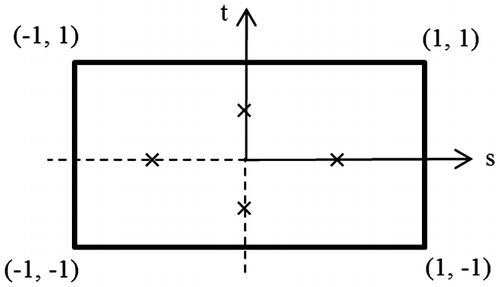
The computational grid used in this study consists of quadrilateral elements, as shown in Figure . A vertex-centred finite volume method, described in [Citation47], is used wherein a control volume is associated with each node. In Figure , typical interior, boundary and corner control volumes are shown. The boundary of each control volume is comprised of a number of planar panels (eight for an interior volume, six for a boundary volume and four for a corner volume). An integration point is located at the middle of each panel. These are denoted by × in Figure . Using the bilinear shape functions (Nj), any scalar with the local coordinates (s, t) in an element (Figure ) can be related to the nodal values of
as follows:
(1)
(1)
Figure 1. Computational grid in a curved nozzle with various control volumes and boundary conditions.
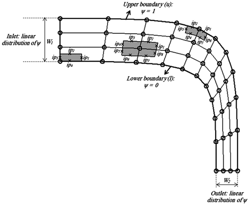
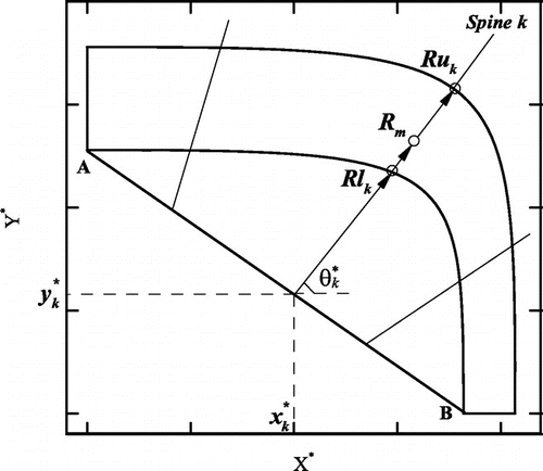
Here, a simple algebraic method is used to generate the computational grid. The method starts by defining a reference line. For example, for the geometry shown in Figure , AB is the reference line from which spines are erected that cross both boundaries of the duct. A typical spine, such as spine k, has origin () and extends in the direction characterised by angle
. The spine k intersects the duct lower and upper boundaries at Rlk and Ruk, respectively. Cartesian coordinates of node m on spine k (xm and ym) are calculated using the spine coordinates (Rlk and Ruk) as follows:
(2)
(2)
(3)
(3)
Parameter rm is user specified and remains constant during the grid evolution.[Citation2] Spine coordinates are beneficial because they effectively reduce a two-dimensional grid generation problem just described to a one-dimensional grid distribution problem. Given the discrete boundary shape, various grid generation tools, including commercial grid generators such as Gambit, can also be employed.
3. The flow solver
For two-dimensional ideal flow with the stream function as the dependent variable, the governing equations and boundary conditions of a SSD problem are as follows:
(4a)
(4a)
(4b)
(4b)
(4c)
(4c)
where represents the outward-directed coordinate normal to the walls. Note that in ideal, flows pressure is related to the velocity through Bernoulli equation and a target tangential velocity is specified instead of the target pressure distribution.
The equation governing the fluid flow and the auxiliary conditions need to be discretized and solved on the discrete solution domain. Here an element-based finite volume method is employed to discretize the governing equation. Satisfaction of Equation (4a) over a control volume corresponds to the balance of a flow-related variable F across the control surfaces as follows:(5)
(5)
It can be shown that [Citation2]:(6)
(6)
And(7)
(7)
where(8)
(8)
And(9)
(9)
Einstein summation rule is applied in Equations (6)–(8). Vertex points with local coordinates (s1, t1) and (s2, t2) in Equation (9) are the end points of the panel containing the integration point ip.
A convenient form of Fip can be developed for internal panels in analysis problems as follows [Citation2]:(10)
(10)
where(11)
(11)
where i, m, n, p and q all refer to values at the nodes of the element containing the integration point ip and they take values of 1–4 corresponding to four nodes of the element containing the integration point ip. Note that Gm is a pure geometrical, or grid-dependent, quantity. Therefore, the balance equation for an internal control volume can now be written as:(12)
(12)
Equation (12), which generates a nine-point computational molecule, provides a constraint on the unknown at an internal node. At the boundary nodes,
is determined by boundary conditions (Equation 4b). The balance equations for all boundary and internal control volumes are assembled to provide the following algebraic set of equations:
(13)
(13)
Solving the above linear set by any proper linear solver provides the unknown stream function values at nodal points. Therefore, whenever the in-house flow solver is called in this study, the equation set corresponding to Equation (13) is solved and the state variables are updated. Obviously, another option for a given computational grid is to call any proper flow or field solver, including commercial software such as ANSYS Fluent, to solve the equation set.
4. The shape updater
Before describing the shape updater used in the proposed algorithm, a typical iterative, physical-based shape updater is described. Afterwards, the shape update procedure in the original direct design method is briefly reviewed. Finally, the shape update method in the proposed algorithm is presented.
4.1. A typical physical-based shape updater
As explained in the review section of the paper, the displacement of each boundary node along the corresponding spine direction (∆ri) can be directly related to the mismatch between the current and target distributions. In the context of an ideal flow, a physical-based iterative shape updater can be formulated as follows:(14)
(14)
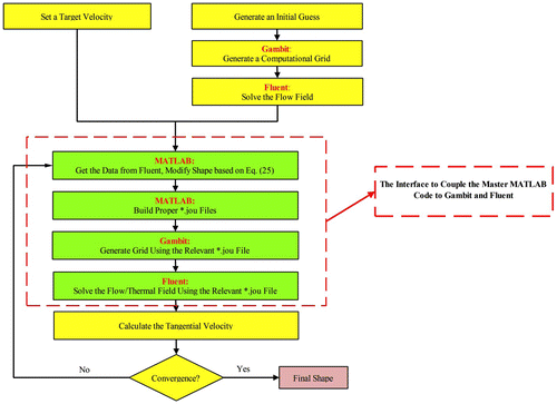
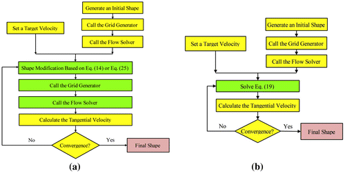
In general, parameter C, which controls the convergence rate, is related to various physical quantities depending on the analogy employed. Large C values might result in divergence and too small C values slow down the convergence drastically. Here, the basis for the determination of this parameter is not discussed and interested readers may consult.[Citation19–22] The flow chart of this algorithm is shown in Figure (a). In this algorithm, after solving the governing equation on the initial grid and calculating , the boundary node coordinates are updated separately using Equation (14). After updating boundary node coordinates, a new computational grid is generated. Afterwards, the flow solver is called and
is calculated to check the following convergence criterion:
(15)
(15)
Figure 4. Three Solution algorithms in the context of duct design problems: (a) proposed and classical iterative algorithms (b) direct design.
In the above equation, n is the number of boundary nodes. Based on the numerical experiments in this study, the desired shape is obtained after two orders of magnitude reduction of the residual (i.e. ε ≅ 0.01).
4.2. Shape update in the direct design approach
In Equation (10), the geometrical part, [Gm]ip, which represents the effect of the computational grid on the flow term at integration point ip (Fip), is a highly nonlinear function of the element nodal coordinates. In the analysis problem, the coordinates of nodal points are known and Fip is a linear function of . Contrary to the analysis problem, in shape design problems both the nodal flow variables and the coordinates of nodal points are unknown and need to be calculated. Therefore, the flow variable Fip at an internal integration point is linearized and rewritten as follows [Citation2]:
(16)
(16)
which results in [Citation2]:(17)
(17)
Introducing xm and ym as defined by Equations (2) and (3) in Equation (17) results in an appropriate equation for flow term (Fip) in terms of the problem unknown when the spine coordinates are employed (i.e. Rl, Ru, and ) [Citation2]:
(18)
(18)
The target tangential velocity (Vt) is imposed through the boundary control volume balances. A convenient formulation for the flow variable at a boundary panel is as follows:(19)
(19)
Equation (19) can also be written in the form of Equation (18). However, note that the balance equations for internal nodes in a SSD problem result in computational molecules containing nine stream function values and six boundary spine coordinates. In contrast, the balance equations for boundary nodes contain three unknown stream function values as well as six boundary spine coordinates. The , Rl and Ru values of the nodes at the inlet and outlet sections of the duct are all known.
Assembling all boundary and internal control volume balance equations result in the following fully coupled set:(20)
(20)
The vector u in this coupled set, which represents a SSD problem, includes unknown internal values and also unknown boundary Rl and Ru values. Flow chart of this algorithm is shown in Figure (b). It is obvious that each solution of the discrete set represented by Equation (20) determines the flow field variable (
) and the location of internal and boundary nodes. Afterwards, the boundary tangential velocity (
) is calculated for the new geometry and the convergence criterion (Equation 15) is checked. If the convergence criterion is satisfied, the algorithm is terminated. Otherwise, the nonlinear iterations are repeated until the convergence criterion is satisfied.
4.3. Shape update in the proposed algorithm
In each iteration of the proposed algorithm, which is an uncoupled method, after solving Equation (13) and obtaining unknown values, a control volume is generated around each boundary node and the balance equations in terms of the unknown surface nodal coordinates are employed to update the shape. The expression for the Fip at internal integration points of these boundary control volumes is proposed as follows:
(21)
(21)
Note that the above expression is exactly satisfied when the final shape is obtained and there is no change in the nodal coordinates (δ[Gm]ip = 0). However, during the design iterations Equation (21) is just an approximation. In fact, when the above expression is compared to Equation (16), one can see that the propose formula for the shape update corresponds to frozen internal stream function values during the shape update in each iterations:(22)
(22)
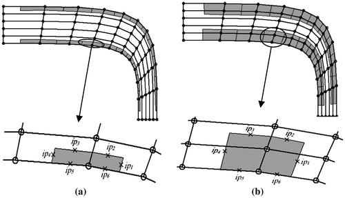
In other words, the proposed algorithm requires the flow field to be fixed during the shape update and the computational grid to be fixed during the flow update. Satisfaction of the fixed flow field assumption during the shape update necessitates the use of relatively large boundary control volumes so that the contributing internal nodes in the corresponding balance equations are not too close to the evolving boundary. Figure (a) shows improperly selected boundary control volumes and Figure (b) shows properly selected boundary control volumes. Use of improperly selected boundary control volumes results in divergence of the iterative solution procedure. Design examples solved in this study show that a combination of two boundary control volumes used in the flow solver is sufficient to obtain a proper boundary control volume for the shape update in the proposed algorithm.
Figure 5. Boundary control volumes in the proposed algorithm: (a) inappropriate control volumes, (b) appropriate control volumes.
Equation (21) can be written as follows:(23)
(23)
Substituting xm and ym as defined by Equations (2) and (3) in Equation (23) results in an equation for the flow term (Fip) in terms of the boundary spine coordinates:(24)
(24)
Similar to the direct design method, the target velocity distribution is imposed through the implementation of boundary values of Fip according to Equation (19).
Using the above expressions for Fip in the balance equations for the boundary control volumes, highlighted in Figure (b), and assembling all the corresponding algebraic equations for these control volumes, result in the following linear set of equations:(25)
(25)
It is important to note that the required steps in both proposed and classical iterative algorithms are the same (Figure (a)), but the shape update methods in these two algorithms are quite different. In the proposed algorithm, the linear set described by Equation (25) is used as the shape updater instead of Equation (14). After updating boundary node coordinates, a new computational grid is generated as mentioned before. Afterwards, the flow solver is called and is calculated to check the convergence criterion.
As mentioned earlier, while the governing equations provide the shape update equations in the proposed method, the flow solver and the shape updater are decoupled in this case and any flow solver can be used to update the state variables. This, in fact, is the distinguished feature of the proposed method as compared to the direct design approach. Obviously, the in-house flow solver can easily be employed as explained before. To incorporate any external flow solver, an interface programme is needed. Here, MATLAB is used to provide a master programme and a computational environment within which other tools, such as grid generator and flow solver, are called in a fully automated manner.[Citation48] As depicted in Figure the MATLAB code first produces two separate journal files (with the extension *.jou) for Gambit (as the grid generator) and ANSYS Fluent (as the flow or field solver). Journal files make it possible to automate the execution of a series of commands.[Citation48] Using MATLAB commands, Gambit and Fluent can then easily read relevant journal files. After each design iteration, journal files are reconstructed to update the information needed by Gambit and Fluent.
5. Solved problems
In order to evaluate the performance of the three above-mentioned algorithms, two different classes of design problems are solved. First, a number of ducts are designed in the context of ideal flow and then the shape of the outer surface of a conducting body is designed so that a prescribed heat flux is achieved.
5.1. Duct design problems
The governing equation and required boundary conditions for this problem were given in Equations (4a)–(4c). It should be noted that the computational results are presented in terms of the following dimensionless variables:(26)
(26)
The normalising parameter W1 is the inlet width of the duct, is a coordinate along the boundary, stotal is the total length of the boundary and vexit is the fluid exit velocity.
5.1.1. Case 1: design of a curved nozzle
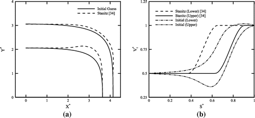
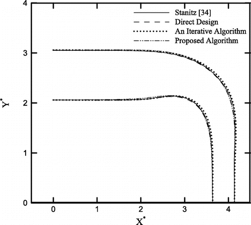
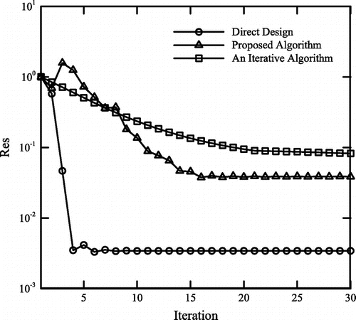
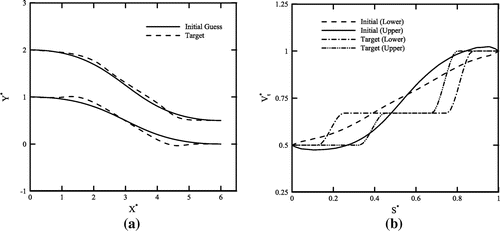
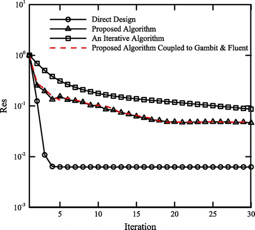
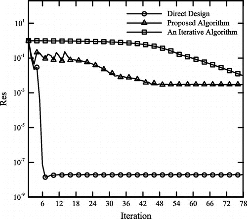
In order to evaluate the performance of the three algorithms introduced before, a 90-deg curved nozzle with an area ratio equal to is designed. The surface tangential velocity corresponding to this curved nozzle has been provided by Stanitz [Citation34]. The initial guess and the final shape, i.e. the Stanitz’s duct, are shown in Figure (a). Figure (b) shows the tangential velocity distributions along the walls of the initial and final shapes. A computational grid similar to the one used in [Citation34], with 65 nodes along the flow direction and 15 nodes across the nozzle, is employed in this study. Figure shows the Stanitz’s nozzle and the shapes reproduced via the three algorithms introduced in this study. Convergence histories of all three algorithms are shown in Figure . Note that each iteration in the direct design algorithm is basically a nonlinear iteration and corresponds to a solution of the equation set represented by Equation (19). In comparison, each iteration in the proposed and classical iterative algorithms corresponds to sequential calls to the grid generator, flow solver and the relevant shape updater. It is clear that the direct design method converges faster to a more accurate solution for the 65 × 15 grid used in this study. The residual in the proposed algorithm levels flat after about 16 iterations and this happens in the classical iterative method after about 25 iterations. Note that the proposed method converges to the solution more accurately as compared to the classical iterative algorithm.
5.1.2. Case 2: design of a straight nozzle
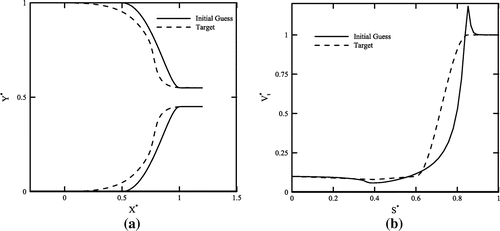
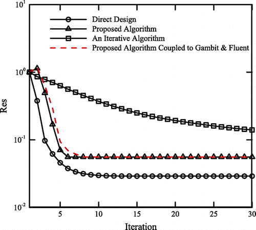
Having verified the performances of different algorithms via Stanitz’s curved nozzle test problem, the algorithms are now employed to design a straight nozzle with area ratio equal to . The initial guess for solving this problem and the corresponding tangential velocity are shown in Figures (a) and (b), respectively. The target velocity distribution is also shown in Figure (b). Using a 65 × 15 computational grid, the calculated shape is also shown in Figure (a). The convergence histories are shown in Figure . Note that the general trends are similar to the ones shown in Figure . Again, the classical iterative method converges rather slowly from the beginning and the convergence rate is really low after the first 30 iterations shown in the diagram. In contrast, both the direct and proposed algorithms converge rapidly initially but computationally stall after about 10 iterations. The convergence history corresponding to the execution of the algorithm shown in Figure is also shown in Figure . Note that use of in-house or external flow solver does not make any major difference as long as the convergence behaviour is concerned. However, the logistics associated with the use of external codes is obviously more due to the required automation of the process and involvement of the interface programme. Order of accuracy differences between different flow solvers affects the computational results. Figure also shows that our in-house flow solver and the Ansys Fluent solver are more or less similar from the accuracy point of view.
5.1.3. Case 3: design of a S-shaped nozzle
The third test case is a s-shaped nozzle with area ratio equal to . The initial guess for solving this problem and the corresponding tangential velocity are shown in Figs. 12a and 12b, respectively. The target velocity distribution is also shown in Figure (b). Using a 65 × 15 computational grid, the calculated shape is also shown in Figure (a). The convergence histories are shown in Figure . The convergence behaviours of the three algorithms are similar the two previous examples. The convergence history corresponding to the execution of the algorithm shown in Figure is also shown in Figure . Once again convergence histories corresponding to the in-house and external flow solvers are quite close to each other.
5.2. Heat conducting body design
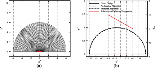
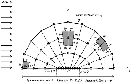
The second group of problems considered here is in the context of steady two-dimensional heat conduction. Steady heat conduction is also governed by the Laplace equation and, therefore, the proposed algorithm can also be employed here. Figure shows a schematic of half of a conducting body with thermal conductivity k which covers a substrate material of length L. Because of symmetry about the y = 0 plane, only the half problem, in the region y ≥ 0, is considered.[Citation6] A typical computational grid, various control volumes and boundary conditions are also shown in Figure . The substrate is kept at Tw (x) and heat is conducted through the body to its outer surface at Ts. Heat is then convected to the ambient at Ta. The prescribed convection heat transfer coefficient at the outer surface is h(x). The objective is to find the body shape such that its outer surface remains at the specified uniform temperature Ts and specified heat flux, qs = h(Ts − Ta). The computational results for this problem are presented in terms of the following dimensionless variables [Citation6]:(27)
(27)
Figure 14. Computational grid in a conducting body with various control volumes and boundary conditions.
Using the above dimensionless variables, the dimensionless heat flux along the outer surface () is obtained as follows [Citation6]:
(28)
(28)
where represents the dimensionless outward-directed coordinate normal to the outer surface of the body. Since the initial guess used in this problem is in general far from the shape that corresponds to the specified
(the ratio of the initial guess area to the target shape area is commonly greater than 20) the design iterations are under relaxed.[Citation42] This is achieved using intermediate target flux distributions (
) along the outer surface as follows [Citation42]:
(29)
(29)
where and
are initial and final dimensionless target heat flux distributions along the outer surface, respectively. N is the number of intermediate targets and is user specified. The convergence criterion for intermediate targets (n < N) is less than 0.1, while for n = N the criterion is smaller than 0.01. It should be mentioned that the convergence criterion and the value of N in these examples have been selected for illustrative purposes only, and have not been optimised for the best convergence. The intermediate targets are only used in the direct design as well as the proposed method. No intermediate target heat flux has been employed in the classic iterative algorithm used in this study.
5.2.1. Case 1: uniform substrate temperature
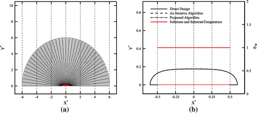
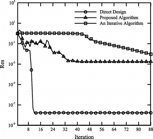
The solution method is first applied to a case with uniform substrate temperature. Similar to the Cheng and Wu’s study [Citation6], the substrate temperature and outer surface temperature are considered θw = 1 and θs = 0.85, respectively. The heat flux on the outer surface is also uniform and defined by Bi = 1 in Equation (28). The initial guess for solving this test case and the corresponding computational grid (a grid with 41 × 41 nodes) are shown in Figure (a). The numbers of the intermediate targets (N in Equation (29)) used for the direct deign and the proposed algorithm are equal to 5 and 6, respectively. The substrate temperature and calculated shapes, obtained by different algorithms, are shown in Figure (b). It is clear that the calculated shapes are in good agreement with that found by Cheng and Wu [Citation6]. Convergence histories of all three algorithms, discussed in this paper, are shown in Figure . Similar to the duct examples, the direct design method converges to a more accurate solution faster than two other algorithms. The value of the residual in the proposed algorithm drops three orders of magnitude and levels flat after about 40 iterations. Initially, the convergence rate of the classical iterative method is rather slow and it increases after about 45 iterations.
5.2.2. Case 2: linear substrate temperature
The substrate temperature in this example is not uniform and varies linearly with as
. The outer surface non-dimensional temperature is θs = 0.5, and uniform heat flux, corresponding to Bi = 1 in Equation (28), is assumed. The initial shape along with its computational grid (a grid with 41 × 41 nodes) and computed shapes obtained by different algorithms and substrate temperature are shown in Figs. 17a and 17b, respectively. The numbers of the intermediate targets (N in Equation (29)) used for direct deign and proposed algorithm are equal to 3 and 5, respectively. It is obvious that to have a constant heat flux on the outer surface, the body must be thinner where the substrate temperature is low and thicker where the substrate temperature is high. Therefore, the calculated shapes in Figure (b) are reasonable and in good agreement with that found by Cheng and Wu [Citation6]. The convergence histories for this test case are shown in Figure . The convergence behaviours of the three algorithms are similar to ones observed in the previous test case.
5.2.3. Case 3: nonlinear substrate temperature
The substrate temperature in this example is a parabolic function, θs = 0.65 and a uniform heat flux, corresponding to Bi = 1, is assumed again. The initial shape along with its computational grid (a grid with 41 × 41 nodes) is shown in Figure (a). The number of the intermediate targets (N in Equation (29)) used for both the direct deign and proposed algorithm is equal to 3. The computed shapes obtained by different algorithms and also the corresponding substrate temperature are shown in Figure (b). Again the computed shapes by all algorithms match well with the optimised shape reported by Cheng and Wu [Citation6]. The convergence histories for different algorithms are shown in Figure . The general trends of convergence histories are similar to the ones obtained in two previous test cases.
Figure 19. Design of a conducting body with nonlinear substrate temperature: (a) initial guess with computational grid, (b) final shapes obtained by three different algorithms introduced in this study.
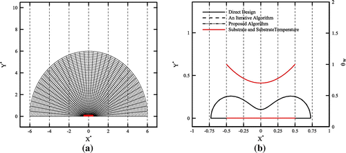
Figure 20. Convergence histories in the conducting body with nonlinear substrate temperature example.
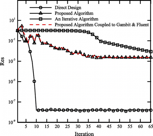
The algorithm shown in Figure can also be used to solve this thermal problem. The convergence history corresponding to the execution of this algorithm is shown in Figure . Very similar convergence behaviours are observed again.
6. Discussion
In all test cases studied, computations were performed using a PC computer with 4.0 GHz eight core CPU and 8.0 GB RAM. Table shows the required CPU time, the number of iterations and residual values corresponding to the mentioned iteration numbers in various algorithms for different test cases. The information presented in Table , and also the convergence history diagrams shown earlier, reveals that the proposed algorithm does not solve the design problem as accurate as the direct design method and usually converges at higher residual values. This behaviour might be explained by noting that the proposed algorithm is formulated based on the assumption. This assumption necessitates the use of relatively larger boundary control volumes as compared to those used in the direct design algorithm. Furthermore, Table shows that the residual of the direct design method levels flat sooner than the proposed algorithm. For instance, in heat conducting body design examples, residual reduction in the proposed algorithm stops at a level approximately 3–6 times greater than the level corresponding to the direct design approach. In comparison, the iterative algorithm does not experience convergence stall and a very slow but continuous residual reduction is observed in all test cases. Just as an example, in heat conducting body design problems, the iterative algorithm needs 120 iterations to reach a residual level similar to the proposed algorithm and 2500 iterations to reach a residual level similar to the direct design method. It is interesting, however, that the residual level is not critically important as far as the final shape is concerned. The designed heat conductor shapes by all three methods are indistinguishable in spite of the differences in residual values.
Table 1. Grid resolution, iteration number, residual level and CPU time for different test cases.
In summary, the proposed algorithm borrows features and ideas from both direct and iterative shape design methods. It needs separate grid generator and flow solver as all iterative algorithms do. However, the shape update procedure is solely based on the governing equations similar to the direct design approach. This latter feature is significant because unlike other iterative methods there is no need to physical analogies, tuning of control parameters or mathematical procedures for finding the search direction and step size in the design space. The convergence behaviour of the proposed algorithm is similar to the direct design. The convergence rate is high initially but flattens afterwards.
7. Conclusion
A new inverse shape design algorithm has been introduced in this paper. The proposed algorithm is inherently iterative because it needs frequent field solutions and shape update to meet the given target pressure distribution or given heat flux along the boundary. However, in contrast to currently used iterative shape design methods, in which the flow governing equations are not employed to update the shape and use of further physical or mathematical considerations are unavoidable, the shape update in the proposed algorithm is solely based on the governing equations. The performance of the proposed algorithm is compared to a previously developed direct shape design method and a typical iterative solution approach. Different 2D nozzles (i.e. curved, straight and s-shaped nozzles) in the context of ideal fluid flow model and different heat spreaders for various substrate temperature distributions in the context of steady 2D conduction are designed via the proposed algorithm and two other algorithms. Moreover, an interface programme is developed which allows the proposed algorithm to employ external grid generators and field solvers. In all of the test problems, the proposed algorithm converges faster than the classical iterative approach and the direct design method is the fastest and most accurate method as compared to other algorithms. To the knowledge of the authors, the proposed algorithm is the only inverse design algorithm that is capable of using available flow solvers and updates the shape just by resorting to the governing equations themselves. Use of the proposed algorithm in the context of viscous flow models is currently under consideration.
References
- Kubo S. Classification of inverse problems arising in field problems and their treatments. In: Tanaka M, Bui DD, editors. Proceedings of 1st IUTAM Symposium on Inverse Problems in Engineering Mechanics; 1992 May 11–16; Tokyo, Berlin: Springer-Verlag, p. 51–60.
- Ashrafizadeh A, Raithby GD, Stubley GD. Direct design of ducts. J. Fluids Eng. 2003;125:158–165.10.1115/1.1514201
- Ashrafizadeh A, Okhovat S, Pourbagian M, Raithby GD. A semi-coupled solution algorithm in aerodynamic inverse shape design. Inverse Probl. Sci. Eng. 2011;19:509–528.10.1080/17415977.2010.530663
- Rao SS. Engineering optimization, theory and practice. 3rd ed. New York (NY): Wiley; 1996.
- Green LL, Newman PA, Haigler KJ. Sensitivity derivatives for advanced CFD algorithm and viscous modeling parameters via automatic differentiation. J. Comput. Phys. 1996;125:313–324.10.1006/jcph.1996.0096
- Cheng CH, Wu CY. An approach combining body fitted grid generation and conjugate gradient methods for shape design in heat conduction problems. Numer. Heat Transfer. 2000;37B:69–83.
- Jameson A, Jones TV. Optimum transonic wing design using control theory. Report for Air Force Office of Science Research under grant no. AF F49620-98-1-2002. Goettingen (Germany); 2002.
- Wang X, Damodaran M, Lee SL. Inverse transonic airfoil design using parallel simulated annealing and computational fluid dynamics. AIAA J. 2002;40:791–794.10.2514/2.1714
- Allen BG, Michael SS. Airfoil design using a genetic algorithm and an inverse method. AIAA Paper No. 2003-0043; 2003.
- Fainekos GE, Giannakoglou KC. Inverse design of airfoils based on a novel formulation of the ant colony optimization method. Inverse Prob. Sci. Eng. 2003;11:21–38.10.1080/1068276031000074288
- Wickramasinghe UK, Carrese R, Li X. Designing airfoils using a reference point based evolutionary many-objective particle swarm optimization algorithm. WCCI 2010 IEEE World Congress on Computational Intelligence; 2010 July 18–23; Barcelona, Spain; 2010.
- Dedoussis V, Chaviaropoulos P, Papailiou KD. Rotational compressible inverse design method for two-dimensional, internal flow configurations. AIAA J. 1993;31:551–558.10.2514/3.11364
- Leonard O, Braembussche. A two-dimensional Navier–Stokes inverse solver for compressor and turbine blade design. Proc. IMECHE, Part A: J. Power Energy. 1997;211:299–307.
- Demeulenaere A, van den Braembussche R. Three-dimensional inverse method for turbomachinery blading design. ASME J. Turbomachinery. 1998;120:247–255.10.1115/1.2841399
- De Vito L, van den Braembussche R. A novel two-dimensional viscous inverse design method for turbomachinery blading. Trans. ASME. 2003;125:310–316.
- Nili-Ahmadabadi M, Durali M, Hajilouy-Benisi A, Ghadak F. Inverse design of 2-D subsonic ducts using flexible string algorithm. Inverse Prob. Sci. Eng. 2009;17:1037–1057.10.1080/17415970903047451
- Nili-Ahmadabadi M, Hajilouy A, Durali M, Ghadak F. Duct design in subsonic and supersonic flow regimes with and without normal shock using flexible string algorithm. Proceedings of ASME Turbo Expo 2009, Orlando, FL, USA, GT2009-59744.
- Nili-Ahmadabadi M, Hajilouy-Benisi A, Ghadak F, Durali M. A novel 2D incompressible viscous inverse design method for internal flows using flexible string algorithm. J. Fluids Eng. 2010;132:031401-1.10.1115/1.4001072
- Nili-Ahmadabadi M, Durali M, Hajilouy A. A novel quasi-3D design method for centrifugal compressor meridional plane. Proceedings of ASME Turbo Expo 2010, Glasgow, UK, GT2010-23341.
- Madadi A, Kermani MJ, Nili-Ahmadabadi M. Application of an inverse design method to meet a target pressure in axial flow compressors. Proceedings of ASME Turbo Expo 2011, Vancouver, British Columbia, Canada, GT2011.
- Nili Ahmadabadi M, Poursadegh F. Centrifugal compressor shape modification using a proposed inverse design method. J. Mech. Sci. Tech. 2013;27:713–720.10.1007/s12206-013-0120-0
- Nili Ahmadabadi M, Ghadak F, Mohammadi M. Subsonic and transonic airfoil inverse design via ball-spine algorithm. J. Comp. Fluids. 2013;84:87–96.10.1016/j.compfluid.2013.05.007
- Barger RL, Brooks CW. A streamline curvature method for design of supercritical and subcritical airfoils, NASA TN D-7770; 1974.
- Milholen WE. An eficient inverse aerodynamic design method for subsonic flows, AIAA Paper No. 2000-0780; 2000.
- Jianzhong Y, Farooq S, Ion P. Iterative inverse design method based on streamline equations. AIAA Paper No. 2003-214; 2003.
- Butterweck M, Pozorski J. Inverse method for viscous flow design using stream-function coordinates. Acta Mech. 2013;224:1801–1812.10.1007/s00707-013-0841-2
- Garabedian P, Mcfadden G. Design of supercritical swept wings. AIAA J. 1982;20:289–291.10.2514/3.7912
- Malone J, Vadyak J, Sankar LN. Inverse aerodynamic design method for aircraft components. J. Aircraft. 1986;24:8–9.
- Campbell RL, Smith LA, Sankar LN. A hybrid algorithm for transonic airfoil and wing design. AIAA Paper No. 87-2552; 1987.
- Bell RA, Cedar RD. An inverse method for the aerodynamic design of three-dimensional aircraft engine nacelles. In: Dulikravich GS, editor. Proceedings of the Third International Conference on Inverse Design Concepts and Optimization in Engineering Sciences, ICIDES-III; Washington, DC; 1991 October 23–25; p. 405–417.
- Malone JB, Narramore JC, Sankar LN. An efficient airfoil design method using the navier–stokes equations. AGARD 1989, Paper 5; 1989.
- Malone JB, Narramore JC, Sankar LN. Airfoil design method using the Navier–Stokes equations. J. Aircraft. 1991;28:216–224.10.2514/3.46015
- Dulikravich GS, Baker DP. Aerodynamic shape inverse design using a Fourier series method. AIAA Paper No. 99-0185; 1999.
- Stanitz JD. A review of certain inverse methods for the design of ducts with 2- or 3-dimensional potential flow. App. Mech. Rev. 1988;41:217–238.10.1115/1.3151894
- Zannetti L. A natural formulation for the solution of two-dimensional or axisymmetric inverse problems. Int. J. Numer. Meth. Eng. 1986;22:451–463.10.1002/(ISSN)1097-0207
- Chaviaropoulos P, Dedoussis V, Papailiou KD. On the 3-D inverse potential target pressure problem. Part 1. Theoretical aspects and method formulation. J. Fluid Mech. 1995;282:131–146.10.1017/S0022112095000061
- Chaviaropoulos P, Dedoussis V, Papailion KD. On the 3-D inverse potential target pressure problem. Part II: Numerical aspects and application to duct design. J. Fluid Mech. 1995;282:147–162.
- Borges JE. Computational method for the design of ducts. Comput. Fluids. 2007;36:480–483.10.1016/j.compfluid.2005.08.013
- Ashrafizadeh A. A direct shape design method for thermo-fluid engineering problems [ Ph.D. thesis]. Waterloo (Ontario, Canada): Mechanical Engineering, University of Waterloo; 2000.
- Raithby GD, Xu WX, Stubley GD. Prediction of incompressible free surface flows with an element-based finite volume method. J. Comput. Fluid Dynamics. 1995;4:353–371.
- Xu WX, Raithby GD, Stubley GD. Application of a novel algorithm for moving surface flows, 4th Annual Conference of the Computational Fluid Dynamics, Ottawa: Society of Canada; 1996.
- Ashrafizadeh A, Raithby GD, Stubley GD. Direct design of shape. Numer. Heat Transfer. 2002;41:501–520.10.1080/10407790190053752
- Ashrafizadeh A, Raithby GD, Stubley GD. Direct design of airfoil shape with a prescribed surface pressure. Numer. Heat Transfer. 2004;46:505–527.10.1080/104077990502989
- Ashrafizadeh A, Raithby GD. Direct Design Solution of the Elliptic Grid Generation Equations. Numer. Heat Transfer. 2006;50:217–230.10.1080/10407790600599009
- Taiebi-Rahni M, Ghadak F, Ashrafizadeh A. A direct design approach using the Euler equations. Inverse Probl. Sci. Eng. 2008;16:217–231.10.1080/17415970701404268
- Ghadak F, Taiebi-Rahni M, Ashrafizadeh A. Direct design of branched ducts. Scientia Iranica, Trans. B: Mech. Eng. 2009;16:111–120.
- Schneider GE, Raw MJ. Control volume finite-element method for heat transfer and fluid flow using collocated variables 1- computational procedure. Numer. Heat Transfer. 1987;11:363–390.
- Joodaki A, Ashrafizadeh A. Surface shape design in fluid flow problems via hybrid optimization algorithms. Aero. Sci. Tech. Forthcoming 2014. Available from: http://www.sciencedirect.com/science/article/pii/S1270963814001345

