 ?Mathematical formulae have been encoded as MathML and are displayed in this HTML version using MathJax in order to improve their display. Uncheck the box to turn MathJax off. This feature requires Javascript. Click on a formula to zoom.
Abstract
A to pological sensitivity approach is developed for the imaging of penetrable solid obstacles embedded in a fluid background medium by way of inverse acoustic scattering. To this end, an asymptotic form for the scattered field caused by a nucleating spherical solid obstacle in the reference fluid medium is derived within the boundary integral equation framework, where the required limiting behaviour of the acceleration field inside the perturbation is established based on solutions of two simplified fluid–solid interaction problems. With this result, the equivalence of acoustic scattering by fluid and solid scatterers in terms of asymptotic behaviour is observed and numerically validated. The direct and adjoint-field topological sensitivity expressions for transient and time-harmonic excitations are obtained accordingly. The utility of the proposed method as a tool for preliminary obstacle reconstruction and bulk modulus characterization is illustrated through numerical examples and an exploratory experimental study. On the basis of adjusted topological sensitivity formulas for fluid reference domains containing pre-existing solid inhomogeneities, an iterative 3D obstacle reconstruction approach is established and its performance with synthetic data is demonstrated.
1. Introduction
The inverse scattering problem of using either far- or near-field patterns of the scattered wave fields to identify obstacles embedded in an acoustic medium is a challenging subject,[Citation1, Citation2] with applications to a wide range of areas such as underwater sonar acoustics, seismic imaging and medical diagnosis. In the context of full waveform analysis, this class of problems is often affiliated with non-linear minimization and thus considerable computational cost due to repeated evaluation of the forward solution [e.g. Citation3, Citation4]. As shown in a number of recent studies, however, sampling-based non-iterative techniques [Citation5, Citation6] that reconstruct obstacles from the distribution of an established indicator function provide a computationally effective preliminary imaging tool. The topological sensitivity method,[Citation7, Citation8] as one of its variants and the focus of this study, formulates the indicator function from a physical standpoint.
The concept of topological sensitivity (TS), since its inception in the context of structural shape optimization,[Citation9, Citation10] has been generalized and applied to deal with inverse scattering problems in acoustics,[Citation7, Citation11–Citation17] electromagnetism,[Citation18–Citation23] and elastodynamics.[Citation24–Citation33] In the reconstruction approach, the TS indicator function is defined as the sensitivity of a given cost functional (that would commonly be used as a platform for non-linear minimization) with respect to the nucleation of an infinitesimal obstacle at a prescribed sampling point in the reference (background) medium. Accordingly, the support of hidden obstacles is exposed through the spatial distribution of topological sensitivity, namely the regions where TS attains pronounced negative values. Typically, the topological sensitivity can be formulated explicitly in terms of either the germane Green’s function or suitable wave fields computed for the reference (scatterer-free) domain, which makes this class of inverse solutions appealing from the computational point of view. With the help of a selected threshold value and minimization of TS with respect to obstacle material parameters, this method may also provide preliminary information about the size and material properties of the hidden obstacle.[Citation28–Citation30]
Concerning the inverse scattering of acoustic waves,[Citation11] introduced the idea of using the topological sensitivity to construct impenetrable obstacles of finite extent in a homogeneous background medium by way of time-harmonic waveforms. This concept was furthered in [Citation7, Citation15] to admit penetrable scatterers and heterogeneous background media. In [Citation12] and [Citation16], the foregoing analyses were extended to the time domain, where the feasibility of exposing (resp. impenetrable and penetrable) scatterers using acoustic wavelets of sufficient smoothness was demonstrated. In these topological sensitivity developments, the vanishing scatterer is assumed to be acoustic, i.e. of perfectly incompressible fluid with zero shear stiffness (Poisson’s ratio = ). However, in a number of relevant engineering applications such as underwater sonar imaging, the hidden scatterer is often a solid body, which is incompatible with the above assumption. For the involved inverse fluid–solid interaction scattering problem, some previous attempts using different methods have been proposed, such as the optimization method, linear sampling method or factorization method [e.g. Citation34–Citation38]. In the context of topological sensitivity method, the case of a scattering solid obstacle in an acoustic (fluid) background medium has not been addressed yet.
To help mitigate the problem, the concept of topological sensitivity is herein particularized to quantify the perturbation of a given cost functional due to the creation of an infinitesimal solid obstacle in the reference acoustic medium. Through preliminary limiting analysis of the boundary integral representation for the scattered field, its asymptotic behaviour is affiliated with the acceleration field inside the vanishing obstacle, which is then derived from solutions of two simplified fluid–solid interaction problems involving spherical obstacles. Here, it is observed and numerically validated that the limiting behaviour of the scattered acoustic field caused by a penetrable solid obstacle is equivalent to that of an acoustic scatterer with the same mass density and bulk modulus, which in a certain sense supports the solid obstacle to acoustic obstacle simplification considered by engineers at a lower computational cost. The topological sensitivity formulas for transient and time-harmonic excitations are expressed explicitly in terms of the incident acoustic field and either (i) the Green’s function or (ii) the adjoint field for the reference (scatterer-free) domain. Through numerical examples and a preliminary experimental investigation, it is shown that the featured developments carry the potential of furnishing both geometric and material information of the hidden scatterers. To further improve the geometric reconstruction of hidden obstacles, an iterative 3D obstacle reconstruction approach is established based on topological sensitivity formulas adjusted for acoustic reference domains with known solid obstacles. Its performance with synthetic data is demonstrated.
2. Direct problem
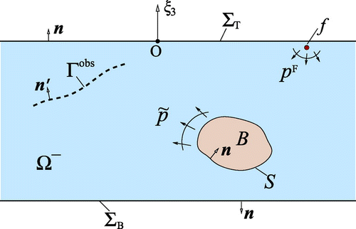
With reference to Figure , consider the fluid layer in a reference Cartesian frame
, housing a solid obstacle
with smooth boundary
. The background fluid, bounded by the top Dirichlet boundary
and bottom Neumann boundary
, is characterized by constant mass density
and bulk modulus
. The prescribed top and bottom boundary conditions are to represent free fluid surface and impenetrable bottom. The solid obstacle is assumed to be elastic, homogeneous and isotropic with mass density
, bulk modulus
and shear modulus
. With the above definitions,
is the exterior region surrounding the obstacle and
with
denotes its boundary. Hereon, it is assumed that (i) the obstacle is acoustically illuminated via transient source distribution
with compact support
,
, (ii) the excitation wavelet
is continuous in time, i.e.
, and (iii) all featured acoustic and elastodynamic fields have quiescent past.
2.1. Free field
In the obstacle-free (reference) medium , the prescribed excitation
gives rise to a pressure distribution
, termed the free field, that satisfies the field equation and boundary conditions:
(1a)
(1a) Here
, where
is the normal on
oriented outward from
,
denotes the acoustic wave speed, and
indicates differentiation with respect to time. In the case of time-harmonic excitation
with angular frequency
, (Equation1a
(1a)
(1a) ) can be reduced to
where the complex-valued denotes the time-harmonic free-field pressure and the time-dependent term
is omitted. Here, it is assumed that
is not an eigenfrequency of any of the boundary-value problems appearing in the analysis.
2.2. Scattered field
Following the usual treatment of scattering problems, perturbation of the pressure field due to the presence of an obstacle can be conveniently quantified in terms of the scattered field
(2)
(2)
where is the (total) pressure field in
generated by
. Assuming that the free field
can be obtained separately beforehand, the forward scattering problem (i.e. the task of calculating
in
given
and
) can be conveniently written in terms of
as follows:
(3a)
(3a)
(3b)
(3b)
(3c)
(3c)
(3d)
(3d)
(3e)
(3e) where the boundary conditions in (Equation3e
(3e)
(3e) ) represent continuity of surface traction and normal acceleration on the fluid–solid interface, see e.g. [Citation39] for the counterpart of (3) in terms of time-harmonic scattering. Here,
is the displacement field inside the solid obstacle,
is the normal on
oriented towards the exterior of
,
is the fourth-order elasticity tensor of the solid obstacle, where denotes the symmetric
th-order identity tensor, and
is the traction vector on
. The radiation condition accompanying (1)–(3) will be introduced next in the form of boundary integral representation.
2.3. Boundary integral representation
To facilitate the ensuing developments, it is useful to recall the Riemann (time) convolution between two spatiotemporal fields, namely(4)
(4)
and to introduce the Green’s function for the reference domain , which satisfies (1) with
, where
is the Dirac delta function whose dimension reflects that of its argument. Let
and
denote, respectively, the time-domain acoustic fundamental solution and its normal derivative for the free space
due to a point source
. Using the method of images,[Citation40, Citation41] the Green’s function
and its normal derivative
for the reference fluid layer
can be written as:
(5)
(5)
where signifies the unit vector in the
direction, and the terms in the series account for the multiple reflections off the top and bottom boundaries of the layer,
and
.
Due to the fact that the reference domain extends to infinity in the
and
directions, (1)–(3) are complemented by the requirement that there is no energy influx from infinity. In the context of infinite media, this requirement is commonly imposed in terms of the Sommerfeld radiation condition.[Citation42] For problems involving waveguides such as that examined in this study, a relevant statement of the radiation condition can be written, following the work of [Citation43] for elastic waves, as
(6)
(6)
where ,
is the support of
,
is a cylindrical surface of radius
and
is the normal on
oriented away from the origin.
On the basis of (1)–(Equation6(6)
(6) ), the scattered pressure field
in the exterior of the obstacle
can be expressed in terms of the boundary distributions of
and
over
as:
(7)
(7)
3. Inverse problem and topological sensitivity
With reference to Figure , consider the inverse problem where a solid obstacle, , characterized by mass density
, bulk modulus
and shear modulus
, is to be reconstructed and identified from the knowledge of: (i) the illuminating transient source distribution
, (ii) the background medium, including the acoustic parameters (
), geometry and boundary conditions, and (iii) observations of the induced pressure field,
, taken over the measurement surface
. In the following analysis, the latter measurements are denoted by
, so that
,
,
under ideal measurement conditions.
To tackle the featured inverse problem, a cost functional quantifying the misfit between the sensory data and their simulations
(computed for a trial obstacle
) is introduced,
(8)
(8)
where ,
collects the material parameters of
, and
is a distance function, assumed to be differentiable with respect to its first argument. A commonly used example of distance function assumes the weighted least-squares format, namely
(9)
(9)
where denote, respectively, the spatial and temporal weighting functions.
3.1. Topological sensitivity
To cater for the reconstruction of penetrable solid obstacles in acoustic media, the concept of topological sensitivity is hereon particularized to quantify the perturbation of the cost functional (Equation8(8)
(8) ) caused by the introduction of an infinitesimal solid “defect” at a sampling point
in the acoustic reference domain
. At sampling points where the TS takes pronounced negative values, the introduction of such perturbation significantly reduces the cost functional, and thus by heuristic inference [e.g. Citation7, Citation17] such sampling points are expected to be inside or near the support of the true obstacle
.
Consider the nucleation of a trial solid obstacle with characteristic size
and material properties
at a sampling point
, where
is a fixed bounded open set with smooth boundary
of class
and volume
containing the origin. On denoting the affiliated exterior domain by
, the topological sensitivity
can be defined through the first-order expansion of
for vanishing
,
(10)
(10)
where(11)
(11)
is the cost functional computed for the free field and
, characterizing the leading term, is a function of the vanishing obstacle size. For completeness, it is further assumed that
(12)
(12)
With reference to (Equation2(2)
(2) ), let
denote the scattered field caused by the infinitesimal obstacle (i.e. solution of the forward transmission problem (3) wherein
is replaced by
). As
, the scattered field
is on physical grounds expected to vanish, i.e.
(13)
(13)
whereas the free field is independent of
. By virtue of this result, (Equation2
(2)
(2) ) written in terms of
and the definition of the cost functional (Equation8
(8)
(8) ),
can be expanded with respect to
as
(14)
(14)
which, together with (Equation10(10)
(10) ) and (Equation11
(11)
(11) ), results in the expression for topological sensitivity,
(15)
(15)
In light of (Equation15(15)
(15) ), the evaluation of topological sensitivity requires the limiting distribution of the scattered field
over the measurement surface
as
. This problem is addressed next.
3.2. Scattered pressure field due to vanishing solid obstacle
To obtain a computable expression for topological sensitivity, consider the scattering problem (3) for a vanishing obstacle where
,
(i.e. the sampling point is separated from the support of acoustic sources used to illuminate the obstacle), and
is a ball of unit radius centred at the origin of the reference Cartesian system. By virtue of the integral representation (Equation7
(7)
(7) ), the governing Equation (Equation1a
(1a)
(1a) ) and the fluid–solid interfacial conditions over
as in (3e), the scattered pressure field in
can be written as:
(16)
(16)
where is oriented towards the interior of
, index “
” is used to indicate quantities that are dependent on the vanishing obstacle size, and the second convolution operator, indicated in boldface, signifies the “vector” convolution defined (using Einstein summation convention) as
in terms of vectors and
with respective Cartesian components
and
.
3.2.1. Limiting analysis
For any given ,
and
, one may expand
,
,
and
in Taylor series about
as
(17)
(17)
where denotes the gradient of
(whereby it is a second-order tensor with components
) and
. With (Equation17
(17)
(17) ), the leading behaviour of (Equation16
(16)
(16) ) as
can then be written as:
(18)
(18)
On the basis of (Equation3e(3e)
(3e) ), the fact that
is a sphere (whereby
can be expressed as
), and the Taylor expansion of
over
, i.e.
(19)
(19)
where the operator “” denotes double dot product [Citation44] (e.g. the double dot product of two second-order tensors
and
is a scalar given by
), one finds that
(20)
(20)
By virtue of (Equation20(20)
(20) ) and the balance of linear momentum (Equation3b
(3b)
(3b) ), (Equation18
(18)
(18) ) reduces to
(21)
(21)
Further evaluation of from (Equation21
(21)
(21) ) requires the acceleration field
in the vanishing obstacle
.
As shown in [Citation45], the governing Equation (Equation3b(3b)
(3b) ) for
corresponds to a regularized boundary integral equation:
(22)
(22)
where is the elastodynamic Green’s function for an infinite solid
with elastic parameters (
) and mass density
, defined as the displacement at
due to a time-impulsive point force
acting at
in the
th direction (
),
is the associated traction, and
signifies integral in the Cauchy principle value sense.
To expose the limiting behaviour of (Equation22(22)
(22) ) as
, the following scaled coordinates,
(23)
(23)
are introduced and the leading asymptotic behaviours of and
are decomposed as
(24)
(24)
where denotes the rigid body motion of
and
is the surface of the unit ball
. As implied by (Equation24
(24)
(24) ), the elastodynamic fields
and
in the vanishing solid obstacle are decomposed into two parts. The first part denotes the regular term of
. It corresponds to a simplified fluid–solid interaction problem where a rigid sphere moves in an inviscid fluid. The second part signifies the infinitesimal term of
as
goes to 0. With further asymptotic analysis, the second part turns out to be associated with another simplified fluid–solid interaction problem that will be found out later.
As for the first simplified fluid–solid interaction problem, considering as an infinitesimal particle in the fluid, its rigid body acceleration
can be calculated using the concept of virtual added mass in fluid mechanics.[Citation46] For a sphere in an inviscid fluid, the added mass is equal to one half of the displaced mass. So that the rigid body acceleration of
is
(25)
(25)
which makes use of the balance of linear momentum in the obstacle-free fluid,(26)
(26)
where denotes the free field acceleration in the reference fluid medium.
On the basis of (Equation23(23)
(23) ) and the singular behaviour of the Stokes fundamental solution,[Citation45] it can be shown [Citation29] that
(27)
(27)
where is the elastostatic Kelvin’s fundamental solution for an infinite solid
with elastic parameters (
) of
,
is the associated traction, and
with
. Substitution of (Equation24
(24)
(24) ) and (Equation27
(27)
(27) ) into (Equation22
(22)
(22) ) yields
(28)
(28)
which makes use of . On dropping the (underlined) higher order term, the integral Equation (Equation28
(28)
(28) ) turns out to be associated with an elastostatic transmission problem where a unit ball
with elastic parameters
and
is subject to a uniform pressure
on its boundary. Therefore, the second part of the
decomposition in (Equation24
(24)
(24) ) is associated with the simplified fluid–solid problem that describes the deformation of a sphere subject to a uniform pressure applied by the surrounding fluid. The solution to this problem can be computed as
(29)
(29)
where and
are, respectively, the rigid body translation and rotation as permitted by the Neumann boundary condition of this problem.
With (Equation24(24)
(24) ), (Equation25
(25)
(25) ) and (Equation29
(29)
(29) ) in place, the two volume integrals in expression (Equation21
(21)
(21) ) for the scattered field
can be evaluated as
(30)
(30) Note that the rigid body acceleration
has a zero divergence with respect to
. From (Equation30
(30)
(30) ), the asymptotic representation (Equation21
(21)
(21) ) for
finally reduces to
(31)
(31)
In case of time-harmonic scattering, (Equation31(31)
(31) ) can be simplified as
(32)
(32)
where and
are the respective counterparts of
and
for time-harmonic excitation. Owning to the linearity of the forward scattering problem with respect to the excitation, (Equation31
(31)
(31) ) and (Equation32
(32)
(32) ) are interchangeable via Fourier transform and its inversion, i.e.
(33)
(33)
where is the excitation wavelet.
Remark
Here, it is important to be aware of that the equivalence between (Equation31(31)
(31) ) and (Equation32
(32)
(32) ) is formal as long as the conditions for invertibility of Fourier transforms [Citation47] are met, which is, however, often troublesome in wave equations.
3.2.2. Discussion and validation
From (Equation31(31)
(31) ) and (Equation32
(32)
(32) ), one may note that the limiting behaviour of the scattered pressure field
does not involve all the material parameters of the trial solid obstacle. Indeed, it depends on the densities and bulk moduli of the background and the trial solid obstacle. Nonetheless, it is important to observe that expressions (Equation31
(31)
(31) ) and (Equation32
(32)
(32) ) are identical to their counterparts for a vanishing acoustic obstacle with mass density
and bulk modulus
.[Citation7, Citation16] This implies that in terms of leading-order behaviour, an acoustic source in the surrounding fluid cannot induce shear in a homogeneous isotropic solid obstacle.
Because of the equivalence of expressions (Equation31(31)
(31) ) and (Equation32
(32)
(32) ), the time-harmonic expression (Equation32
(32)
(32) ) is validated for simplicity. First, the
validity of (Equation32
(32)
(32) ) for configurations with both
and
is tested. Consider a solid ball
of radius
, located at
in the full space
characterized by mass density
and bulk modulus
, where
is the reference length. The ball is elastic and isotropic with the same mass density
and bulk modulus
as the background. The Poisson’s ratio
of the ball takes 0.25 (the shear modulus
). A time-harmonic excitation with frequency
is applied at
. The induced scattered pressure field
is computed at a number of points
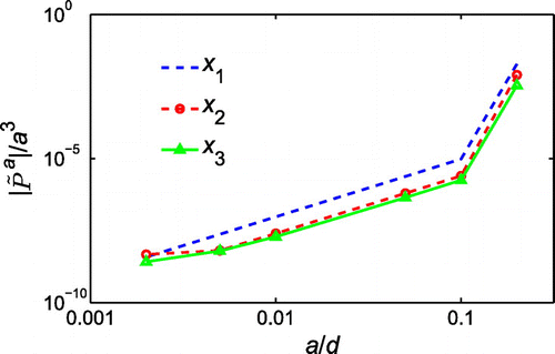
using a boundary element method [Citation48] tailored for fluid–solid coupling,[Citation49] while the free field and Green’s functions are calculated analytically. Figure shows the variation of
with respect to the obstacle size
at a few field points. As
,
goes to zero rapidly. A number of similar configurations have been tested and the same trend is observed, indicating that the scattered pressure field
is of smaller order than
, which thus verifies the
term in expression (Equation32
(32)
(32) ).
Next, the coefficients of the two terms in (Equation32
(32)
(32) ) are validated. For obstacles with either
or
, (Equation32
(32)
(32) ) can be rewritten as
(34)
(34)
where and
denote the coefficients related to
and
, respectively. Note that as
, the values of
and
do not depend on the location of the obstacle
, the measurement point
and the excitation frequency
. To facilitate the validation of (Equation34
(34)
(34) ), let
(35)
(35)
(36)
(36)
denote the counterparts of and
for small
, where the scattered field
can be computed numerically. The correctness of (Equation34
(34)
(34) ) can be validated if
(37)
(37)
for any ,
and non-eigenfrequency
.
Let the solid ball in the testing configuration take material parameters different from those of the background. Figure shows the
and
versus
curves at a field point
for different sets of
and
. Note that
indicates that the scatterer is acoustic, i.e. having zero shear modulus. As can be seen from the display, both
and
tend to 1 as
goes to 0. A number of configurations with different
,
and
values have been tested and the same trend is observed, which thus validates the correctness of the coefficients. On comparing the last two curves in each plot, it can be seen that when the mass density
and bulk modulus
of the obstacle are kept the same, the change of shear modulus
(Poisson’s ratio
) does affect the scattered field, however, its influence should be of higher order and therefore the coefficients are expressed in terms of the mass density and bulk modulus.
3.3. Formulas for topological sensitivity
By analogy to the developments in [Citation7, Citation16], two alternative expressions for the topological sensitivity can be established. On substituting (Equation31(31)
(31) ) into (Equation15
(15)
(15) ) and taking
, the “direct” topological sensitivity formula is expressed as:
(38)
(38)
in terms of the Green’s function for the reference domain
.
In case that such Green’s function is unavailable, (Equation38(38)
(38) ) can be formulated alternatively using a so-called adjoint field. The adjoint field,
, is defined as the response of the reference domain
due to virtual excitation
applied over the measurement surface
. Subject to applicable radiation condition, this adjoint field solves the boundary-value problem
(39a)
(39a)
(39b)
(39b)
(39c)
(39c)
(39d)
(39d) where
is the unit normal on
and
. The boundary conditions (Equation39b
(39b)
(39b) ) and (Equation39c
(39c)
(39c) ) indicate that across
, the pressure is continuous but its normal derivative is discontinuous. Such discontinuity is to be interpreted in the sense of a single-layer potential and treated as a distribution of acoustic sources over
. Here, it should be noted that the homogeneous boundary condition in (Equation39d
(39d)
(39d) ) is a deliberate choice to allow recognization in (Equation38
(38)
(38) ) the integral representation of the adjoint field. For the least-squares distance function in (Equation9
(9)
(9) ), the virtual excitation is given by the time-reversed data residual, i.e.
On the basis of (39), the adjoint field and its gradient can be expressed in terms of the Green’s function as:
(40)
(40)
By virtue of this result, change of integration variables and commutativity of the convolution operator, (Equation38(38)
(38) ) can be rewritten in terms of the adjoint field as:
(41)
(41)
which also makes use of the Green’s function reciprocity, i.e. . Without the requirement of a Green’s function, such adjoint-field topological sensitivity formula (Equation41
(41)
(41) ) can be applied to homogeneous reference domains of arbitrary shape and boundary condition, and in this case the adjoint field
can be computed numerically via a suitable (e.g. boundary element) solution scheme. An extension of these developments to heterogeneous reference domains may be established as those in [Citation15, Citation30]; such a generalization is, however, not addressed here.
For inverse scattering problems with time-harmonic excitations, (Equation38(38)
(38) ) and its adjoint field counterpart (Equation41
(41)
(41) ) can be simplified as
(42)
(42)
and(43)
(43)
From (Equation38(38)
(38) ) and (Equation41
(41)
(41) )–(Equation43
(43)
(43) ), the computation of topological sensitivity does not involve the shear modulus
of the vanishing obstacle; therefore, let
from here on for simplicity.
Remark #1 As derived and validated in Section 3.2, the limiting behaviours of the transient and time-harmonic scattered pressure fields and
caused by an infinitesimal solid obstacle in a fluid background medium are identical to their counterparts for a vanishing acoustic obstacle with the same mass density and bulk modulus, and therefore the resulting direct and adjoint field topological sensitivity formulas (Equation38
(38)
(38) ) and (Equation41
(41)
(41) )–(Equation43
(43)
(43) ) for the inverse acoustic scattering of solid obstacles are also the same as their counterparts for the acoustic/acoustic interaction, see e.g. [Citation7] and [Citation16] for the time-harmonic and time-dependent cases, respectively, which again implies that the shear wave in the vanishing obstacle plays at most a second-order role.
Remark #2 As for the elastic/elastic interaction, the topological sensitivity formulas for time-harmonic and transient excitations can be found in e.g. [Citation28] and [Citation29]. For comparison, the direct time-harmonic TS formula [Citation28] is given here,(44)
(44)
where denotes the time-harmonic force distribution,
and
are the free-field displacement vector and stress tensor,
denotes the displacement measurements,
is the unit vector in the
th coordinate direction,
and
constitute the time-harmonic elastodynamic Green’s function for the reference elastic medium
by denoting the respective displacement vector and stress tensor at
due to a unit point force acting at
in the
th direction, and
is a fourth-order tensor depending on the shape
and material parameters
of the infinitesimal trial obstacle. The corresponding TS formula (Equation42
(42)
(42) ) for solid obstacle in fluid background takes a similar form as the expression (Equation44
(44)
(44) ) for elastic/elastic scattering. Actually, the case of solid obstacle in fluid background can be considered as a particular case of elastic/elastic scattering where the shear modulus of the reference medium is zero. However, we did not find a way to particularize the results for elastic/elastic scattering to this particular case.
4. Numerical examples
In previous studies [Citation7, Citation28–Citation30] involving acoustic scattering by acoustic scatterers or elastic scattering by solid scatterers, the topological sensitivity has been shown to be an effective tool for preliminary obstacle reconstruction and material characterization through an assembly of sampling points with pronounced negative TS values and a pointwise identification of “optimal” obstacle properties that minimize the TS at each sampling location. In what follows, these possibilities in terms of acoustic scattering of solid obstacles are explored using the example of a fluid layer containing penetrable solid obstacles.
4.1. Testing configuration
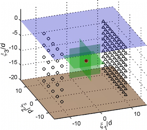
With reference to Figure , consider the synthetic testing configuration where a solid obstacle is embedded in a homogeneous fluid layer
with Dirichlet top surface
and Neumann bottom surface
, where
is the reference length. The obstacle is a ball of radius
centred at
. The background acoustic medium is characterized by mass density
and bulk modulus
. The solid obstacle
is elastic, homogeneous and isotropic with mass density
, bulk modulus
and Poisson’s ratio
. Such material parameters are chosen to mimic an obstacle without acoustic impedance (defined as
) contrast that is usually difficult for conventional reflection-based methods to detect.
To expose the hidden obstacle, the problem domain is sequentially illuminated by point sources equally spaced on a source grid
and for each source location
the induced pressure
is monitored by all the receivers on a measurement grid
, as shown in Figure . For such multi-source illumination, the topological sensitivity can be computed as
(45)
(45)
where is the single-source topological sensitivity, obtained by applying corresponding topological sensitivity formulas (Equation38
(38)
(38) ) or (Equation41
(41)
(41) )–(Equation43
(43)
(43) ) to the testing configuration with only the
th point source
.
Again, the synthetic observations are computed with the aid of a boundary element method [Citation48] tailored for fluid–solid coupling,[Citation49] while the free field
and the adjoint field
are calculated using the Green’s function (Equation5
(5)
(5) ), truncated at
. Note that in this case the topological sensitivity can also be computed directly using the “direct” formulas (Equation38
(38)
(38) ) and (Equation42
(42)
(42) ) since the Green’s function is available. Furthermore, it should be noted that the topological sensitivity formulas are independent of the numerical implementation used to compute the wave fields required.
4.2. Time-harmonic excitation
For the time-harmonic example, the synthetic measurements are generated at an excitation frequency(46)
(46)
where is the acoustic wavelength in the background medium. Here, the selected frequency falls into the so-called resonance region, characterized by wavelengths comparable to or larger than the characteristic dimension of the scatterer.[Citation50] Assuming that
for the vanishing obstacle, the topological sensitivity values
over the three cross-sections passing through the centre of the obstacle (Figure ) are calculated using (Equation43
(43)
(43) ). Note that a uniform spatial weighting function
is used, i.e. all the measurement points are equally weighted. The spacing between sampling points is
.
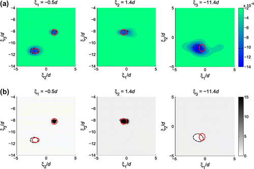
Figure plots the sectional distributions of , where the location and approximate geometry of the obstacle (white circle in the plot) are indicated by pronounced negative TS values. From Figure , it can also be seen that the reconstructed obstacle is elongated in
-direction due to limited aperture.
Figure 5. Sectional distributions of : one obstacle (
and
, indicated by white line), time-harmonic excitation (
).

In practice, experimental data always involves noise. To test the sensitivity of the TS imaging method to measurement noise, random noise is added to the synthetic pressure data and in this case
. As an illustration, the topological sensitivity distributions for the same testing configuration with uniformly distributed random measurement errors in the range of
5%,
10% and
20% are computed, respectively. Figure displays the
and
TS distributions with different levels of measurement noise (the quality of TS distribution at
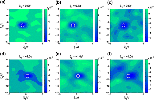
is in between and thus not displayed). On comparing these diagrams to their no-noise counterparts in Figure , it is seen that no significant image deterioration is observed for 5% measurement noise, the TS distributions with 10% noise are somewhat distorted but still acceptable, whereas the TS results with 20% noise are noticeably distorted especially for the cross-section
. From Figure , it can also been seen that the TS distribution at
is more sensitive to noise due to limited aperture.
Figure 6. Sectional distributions of with measurement noise: (a) 5% random noise, (b) 10% random noise, (c) 20% random noise, (d) 5% random noise, (e) 10% random noise, and (f) 20% random noise.
As discussed in Section 3.2.2, the shear modulus of the solid obstacle will affect the scattered acoustic field, i.e.
depends on
, and thus the topological sensitivity depends on
. To investigate the influence of
, the topological sensitivity for obstacles with the same mass density
and bulk modulus
but different Poisson’s ratio
(shear modulus
) is computed. The sectional distributions of TS for obstacles with different shear moduli are compared in Figure . The TS values are very close and the TS distributions are almost the same, which indicates that the shear modulus of the solid obstacle has a very small influence on the topological sensitivity when its mass density and bulk modulus are kept fixed.
Figure 7. Sectional distributions () of
for obstacles with different Poisson’s ratio: one obstacle (
and
, indicated by white line), time-harmonic excitation (
).

Remark
From another point of view, the pressure fields computed for the fluid–solid problems with
may be considered as noisy observation data of
(solution of the acoustic problem) if their differences are less than 5%. Here, the mean relative errors when comparing the solutions for
with an interval of 0.05 with that of the acoustic case
are computed. It turns out that the mean relative errors are between 0.3% and 2% although the maximum relative error can reach 35%. Different sets of
,
parameters for selected values of
are also tested and the mean relative errors between
and
are less than 5%. These results also support the solid obstacle to acoustic obstacle simplification.
4.3. Material characterization
In a number of TS studies,[Citation7, Citation28–Citation30] the topological sensitivity has also been employed as a preliminary material characterization tool, where the topological sensitivity value at each sampling point is minimized with respect to the material parameters of the trial obstacle and the trial material parameters generating the most negative TS value are considered as an estimation of the relative (compared to the background) material parameters of the true obstacle. Here, the above -distributions are generated assuming full prior knowledge about the material properties
of the hidden obstacle, an information that is often not available. To explore the potential of topological sensitivity towards material characterization, the TS at the centre of the obstacle
is evaluated with varying trial material property
or
while the other parameter takes a “predefined” fixed value.
Figure 9. Sectional distributions of and
with
-level isosurface: one obstacle (
and
, indicated by red line), time-harmonic excitation (
). (a) Optimized topological sensitivity
, and (b) Normalized point-optimal bulk modulus
.
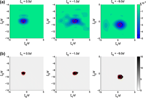
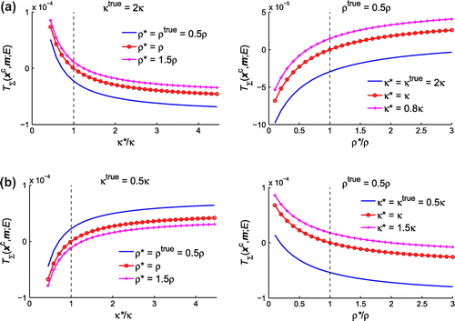
Figure plots the variations of with respect to
and
for two material configurations, (
) and (
). The Poisson’s ratio of the obstacle is still 0.25. As can be seen from the display, the trend of
versus
towards negative
points to the true bulk modulus
, even at highly mismatched
values. However, the trend of
versus
towards negative
is not always consistent with the direction of true mass density
. A number of supplementary examples have been calculated and the above observation still holds.
Owing to the revealing dependence of on
as shown in Figure , a preliminary material characterization approach can be established through a pointwise minimization of
with respect to the trial bulk modulus
. For each sampling point, the optimized bulk modulus
is given by
(47)
(47)
where is the search interval for
and
takes predefined value
. Consequently, the TS value corresponding to
is denoted by
, where
. With such an approach, simultaneous geometric and material characterization of hidden obstacles can be accomplished by:
| (1) | Geometrically reconstruct the obstacle using an isosurface computed with respect to the global minimum, | ||||
| (2) | Estimate the bulk modulus of the obstacle using the point-optimal bulk modulus computed by | ||||
In practice, such preliminary geometric and material information could be used as the initial “guess” for gradient-based, non-linear minimization approaches (e.g. [Citation51]) or form the basis of iterative obstacle reconstruction schemes (e.g. [Citation15, Citation52]).
4.4. Transient excitation
To take advantage of multi-frequency illumination, a raised cosine wavelet [Citation6] given by(50)
(50)
is used as the input signal, where denotes the offset of the peak load. On taking
,
, and
, the time-domain wavelet and its frequency spectrum are plotted in Figure . The temporal synthetic data
are still simulated using the frequency-domain boundary element code.[Citation49] Time-harmonic simulations are performed over the frequency range
with a step of 0.08. To avoid zero frequency, zero is replaced by a small value
. The resulting frequency-domain data are then multiplied by the frequency spectrum in Figure (b) and inverse Fourier-transformed to give the temporal signal.
Figure 10. Input signal: raised cosine wavelet and its frequency response. (a) Time-domain input signal, and (b) Frequency spectrum.

With reference to (Equation41(41)
(41) ), (Equation45
(45)
(45) ) and the material optimization method established above, the sectional distributions of optimized topological sensitivity
on the three cross-sections are displayed in Figure . Note that uniform spatial and temporal weighting functions
and
are used. The predefined mass density takes
and the search interval for the trial bulk modulus is the same as in the time-harmonic example. Similar to the results in Figure , the regions where
takes pronounced negative values point towards the true obstacle and the obstacle is identified correctly as “stiffer” than the background medium because
inside the reconstructed obstacle. In terms of locating the obstacle, transient excitation gives much clearer TS distributions.
Figure 11. Sectional distributions of with
-level isosurface: one obstacle (
and
, indicated by red line), transient excitation (raised cosine with
and
).

To examine the influence of and seek a better estimation of
, the true mass density of the obstacle
is taken as the predefined mass density for TS computation. However, the results are very similar to their counterparts shown in Figure (and thus not displayed here). In the reconstructed obstacle, the TS goes to negative as
increases and does not reach a most negative value at
, and thus cannot provide a better estimation other than “stiffer” or “softer”.
4.5. Multiple obstacles
Next, the applicability of the foregoing developments to more complex situations is examined by a testing problem involving two solid obstacles with different material properties. The reference fluid layer and source-observation setup are the same as in previous examples. The first obstacle is located at and has the same geometry and material properties as the obstacle in Figure . The second obstacle is a “softer” ellipsoidal solid object characterized by mass density
, bulk modulus
and Poisson’s ratio 0.25. It is centred at
and has semi-axes
aligned with the reference Cartesian frame. The obstacles are illuminated by transient excitations in the form of raised cosine (Figure ).
On taking the same predefined mass density and search interval for the trial bulk modulus, Figure plots the sectional distributions of optimized topological sensitivity and normalized point-optimal bulk modulus
on three selected cross-sections, where both obstacles are detected and correctly identified as one “stiffer” and the other “softer”.
5. Iterative 3D obstacle reconstruction
In a few recent studies [Citation15, Citation52–Citation54] dealing with acoustic and electrical impedance tomography problems, the topological sensitivity has been effectively employed to iteratively update the geometric approximations of hidden/buried obstacles. By analogy to these developments, an iterative 3D obstacle reconstruction approach based on the topological sensitivity established for acoustic scattering of solid obstacles is established and verified in the following analysis.
5.1. Iterative algorithm
To facilitate the iterative application, the adjoint-field topological sensitivity formulations (Equation41(41)
(41) ) and (Equation43
(43)
(43) ) are conveniently adjusted to acoustic reference domains containing pre-existing solid inhomogeneities/obstacles. In this case, both the free and adjoint fields in (Equation41
(41)
(41) ) can be redefined with respect to the reference domain
with known solid obstacles
. For the free field, one has
(51)
(51)
where and
are the mass density and elasticity tensor of
,
denotes the displacement field inside
, and
denotes the surface traction on
. For the adjoint field, one has
(52)
(52)
where and
denote the displacement and surface traction for the
th obstacle, respectively. Similarly, the free and adjoint fields in (Equation43
(43)
(43) ) can be redefined by the counterparts of (Equation51
(51)
(51) ) and (Equation52
(52)
(52) ) with time-harmonic excitations.
Remark
Note that the topological sensitivity formulas (Equation41(41)
(41) ) and (Equation43
(43)
(43) ) with free and adjoint fields computed using (Equation51
(51)
(51) ) and (Equation52
(52)
(52) ) or their time-harmonic counterparts are under the assumption that the sampling points are outside existing solid obstacles. In [Citation15], the topological sensitivity formula for sampling points inside existing acoustic scatterers has been derived. However, the situation here is different in that the existing obstacles are solids. For a sampling point
inside an existing solid obstacle
, the free and adjoint fields defined by (Equation51
(51)
(51) ) and (Equation52
(52)
(52) ) would be in terms of displacements
,
and their associated stresses. Thus, the TS formulas (Equation41
(41)
(41) ) and (Equation43
(43)
(43) ) obtained for a vanishing obstacle in a fluid background and expressed in terms of pressure fields
and
would be inapplicable. In this case, the infinitesimal trial solid defect
should be introduced into a solid reference body surrounded by an acoustic medium. With some generalization, the topological sensitivity formulas established for inverse elastic scattering such as those in [Citation28–Citation30] may be applicable to this situation, which is however beyond the scope of this study.
With topological sensitivity formulas for reference domains with known solid obstacles in place, the obstacles reconstructed at a certain step can be considered as pre-existing obstacles for the computation of topological sensitivity at the next step, which thus allows the implementation of an iterative procedure. To focus on the performance of topological sensitivity for obstacle reconstruction, here the material properties (mass density, bulk modulus and shear modulus) of hidden obstacles are assumed to be known beforehand. The 3D distribution of topological sensitivity, calculated using proper TS formulas, is used to iteratively update the geometry of hidden obstacles. The procedures, similar to those in [Citation15, Citation52–Citation54], are described in the following.
Find the initial reconstructions of hidden obstacles
using the distribution of topological sensitivity as illustrated in Sections 4.3 and 4.4. At this step, a tight threshold value
between 0.95 and 1.0 is applied to avoid overestimation of the obstacle and the condition that
with
is checked.
At each step,
Solve the forward (free field) and adjoint problems with
,
and compute
for
.
Set
, which generates a monotonic sequence of approximations through adding regions. The starting value for the threshold
can be taken referring to previous examples.
Check that
. Otherwise, increase the threshold until this condition is satisfied. The upper bound on the threshold value is 1.0 and with this threshold the obstacle approximation from the previous step keeps unchanged, i.e.
.
Check the stopping criterion: the iteration stops if
or
is small enough.
5.2. Numerical experiments
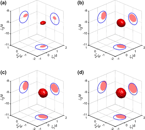
The numerical example presented in Section 4.2 is used for a first illustration. The initial 3D reconstruction based on TS images displayed in Figure is shown in Figure (a), where the reconstructed obstacle and its projections on the three coordinate planes are in red and the projections of the true obstacle are represented with blue solid lines. The ball-shaped obstacle is reconstructed as an ellipsoid, elongated in the direction. On taking this ellipsoid as a pre-existing obstacle, the topological sensitivity in the exterior of the ellipsoid is computed using the adjoint-field TS formula with redefined free and adjoint fields. The sectional distributions of
and the 3D reconstruction at the second iteration are displayed in Figures and (b), respectively, where the reconstructed obstacle is expanded in the
and
directions. The 3D reconstruction results for the third and fourth iterations are shown in Figure (c) and (d). The location and geometry of the 3D reconstruction have stopped to improve although they are still not very close to those of the true obstacle. The reconstructed obstacle is considerably shifted and deformed in the
direction, due to limited aperture in this dimension.
Figure 14. Sectional distributions of at the second iteration: one obstacle (
and
, indicated by white line), time-harmonic excitation (
). The white shape corresponds to the initial reconstruction.

To improve the 3D reconstruction, the testing configuration shown in Figure is supplemented by an opposite set of source and receiver grids, located at and
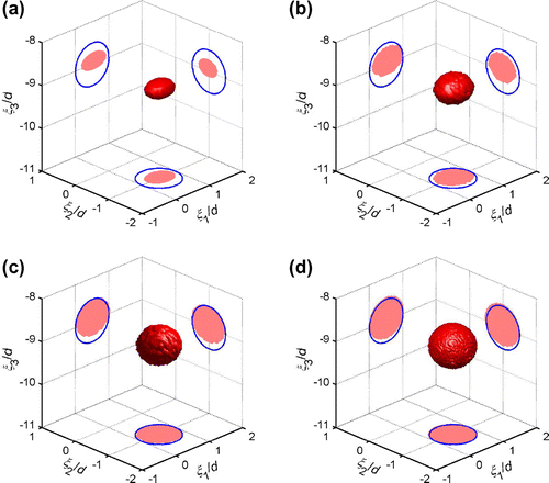
, respectively. The topological sensitivity values, computed using both sets of source and receiver grids, are added together for 3D obstacle reconstruction. The obtained sequence of 3D approximations is displayed in Figure , where the location and geometry of the reconstructed obstacle are significantly improved after only seven iterations. The reconstructed obstacle can be considered as an ellipsoid centred at
, with semi-axes
. These estimations are very close to their true values, i.e. centre
and radius
. Considering the limited aperture of the source and receiver grids, the 3D obstacle reconstruction results are satisfying.
6. Preliminary experimental application
Notwithstanding the progress made on the theoretical formulation of the topological sensitivity method, there are only a few number of studies that demonstrate its usefulness through experimental data.[Citation55–Citation57] In what follows, the effectiveness of the topological sensitivity formulas obtained above is examined using preliminary experimental data.
6.1. Experimental setup
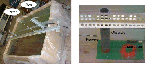
As shown in Figure , a PVC tube with inner and outer radii 2.4 and 3.0 cm, standing on the bottom of a large box filled with water, is the obstacle to be identified. The dimensions of the box are 2.5 m1.8 m and the depth of water is about 43 cm. On taking
kg m
and
m s
, the bulk modulus of water is
GPa. The mass density and wave speed of the PVC tube are measured as
kg m
and
m s
, respectively, and thus its bulk modulus is
GPa. Two RESON hydrophones with model numbers TC4033 and TC4013 are used as the transducer and receiver, respectively. A metal frame is designed to hold the hydrophones and adjust their positions. An Agilent 33220A waveform generator is used to generate the input signal for the transducer and the received signal is recorded using a Sigma S60-4 oscilloscope. The hydrophones used here are sensitive in the frequency range of 5–170 kHz. In this experiment, only one receiver is used since receivers also act as obstacles in water.
To obtain meaningful and high-quality data, special attentions are paid to the following factors.
| (1) | Signal noise. To reduce random signal noise, a number of measurements of exactly the same experiment are averaged as the measured output and the recovery period for repeated tests should be long enough to guarantee a quiescent past. | ||||
| (2) | Point source and receiver. To satisfy the point source and receiver assumption made in the numerical calculation, the two hydrophones (although specified as omnidirectional) should be separated by a certain distance and here the distance is around 20 cm. The way how the hydrophones are held also affects the pressure field and it is observed that the influence of the stems is relatively small when they are parallel with the hydrophones (Figure ). Furthermore, the underwater parts of the metal frame are as far as possible from the hydrophones and the stems are thin to minimize their disturbance. | ||||
| (3) | Waveform and duration of the input signal. To compare with the computed result, the received signal is modified by keeping only the direct arrival with frequency components in the range of 5–170 kHz where the frequency responses of the hydrophones are available. However, a significant difference between simulated and measured responses is still observed when the input signal takes the form of a half-sine pulse of 10 | ||||
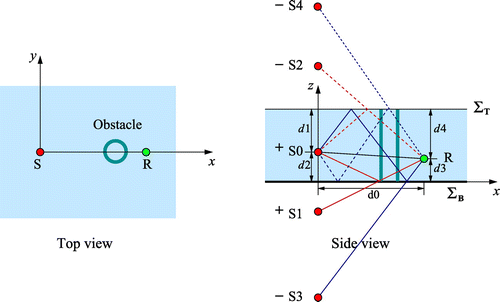
| (4) | Reflections. As shown in Figure , a plastic layer is used to make the wood box waterproof, and thus the surface is not really a “rigid” surface. To consider the bottom surface | ||||
| (5) | Positions of the hydrophones. To avoid the difficulty of direct measurement, the reflections from the top and bottom surfaces are used to determine the positions of the hydrophones. Figure shows the top and side views of the experimental setup. The | ||||
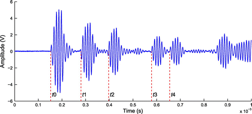
Figure shows the originally received signal when there is no obstacle. The direct arrival time is denoted by while the arrival times of the first four reflections are denoted by
–
, respectively. From Figures and , the following system of equations can be obtained,
(53)
(53)
where is the starting time of the input signal. With (Equation53
(53)
(53) ) and the arrival times obtained from Figure , the unknown distances
–
can thus be calculated with a precision of 1/10 of the wavelength, i.e. 1.5 mm. In this experiment, the distances
–
are 21.54, 23.74, 20.02, 14.12 and 29.64 cm, respectively. And the depth of water is
cm. With reference to the coordinate system shown in Figure , the coordinates of the source and receiver are (0, 0, 20.02 cm) and (21.54 cm, 0, 14.12 cm), respectively.
6.2. Identification of the obstacle
Figure plots the observed free-field pressure without the obstacle and the observed pressure
when the obstacle is present, where the recorded signals are converted to pressure using the frequency response of the receiver and only the first four reflections are considered. Since the pressure to voltage response of the receiver is available only in the frequency range of 5–170 kHz, the observed pressure waves, shown in Figure , only contain frequency components in this range.
With reference to (Equation41(41)
(41) ), the evaluation of topological sensitivity requires the free field and adjoint field in the reference domain. To this end, here the direct arrival part
of the observed free-field pressure
at the receiver and the transfer function of water are used to back-calculate the pressure wave
sent from the source S, namely
(54)
(54)
where is the Fourier transform operator,
denotes the distance between the source and receiver,
is the frequency and
is the wave speed in water. With
in place, the free-field pressure (including the reflections) at any point of the problem domain can be computed using the transfer function of water. The simulated free-field pressure at the receiver is also shown in Figure . It is comparable to the observed free-field pressure but the reflections are smaller in magnitude. Given the observed pressure waves
and
, the adjoint field pressure
, defined as the response of the reference domain due to the time-reversal data residual
applied at the receiver location, can be calculated directly using the transfer function of water. Note that the virtual sources due to reflections from the top and bottom surfaces should be accounted for as before.
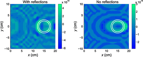
With the treatments described above and assuming the true material properties, the topological sensitivity is computed over a sampling grid
at
cm, with and without considering the four reflections from the top and bottom surfaces. Figure displays the resulting TS distributions. They are symmetric with respect to the
axis owing to the symmetry of the experimental setup. Due to the fact that the reflections are not simulated very well (Figure ), the TS distribution calculated without considering the reflections (using only the first arrival) gives better results, from which, the PVC tube (indicated by white circles) is clearly located. TS distributions considering different number of reflections (1, 2 or 3) are also calculated, however, the results are worse than that without reflections. Therefore, in the following analysis, the topological sensitivity is calculated using only the first arrival.
Figure 20. Simulated free-field pressure, observed free-field pressure and observed pressure when the obstacle is present.
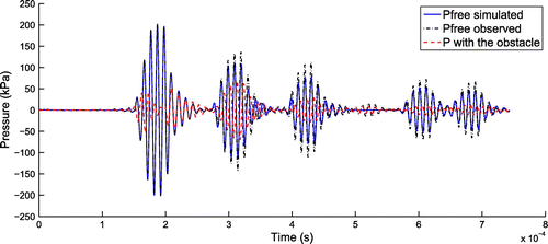
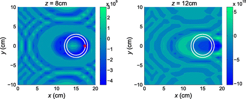
Figure plots the sectional distributions of topological sensitivity at two more cross-sections cm and
cm, where the location of the PVC tube is also approximately identified. Note that at
cm, the topological sensitivity is positive at the centre of the PVC tube
(15 cm, 0 cm, 8 cm) and takes the most negative value at point
(17.3 cm, 0 cm, 8 cm), denoted by a red “
” on the plot.
The variations of topological sensitivity with respect to at the centre of the PVC tube on
cm and
cm and at
on
cm are plotted in Figure . The topological sensitivity goes to negative as
increases, which correctly indicates that the obstacle is “stiffer” than the background. From the plots, it can also be seen that the quality of experimental TS images is not as good as the numerical results, due to the discrepancy between simulations and experiments. However, the potential of topological sensitivity for preliminary geometric reconstruction and material characterization regarding the bulk modulus
is clearly demonstrated.
To further improve the geometric approximation of the tube, the iterative 3D obstacle reconstruction approach developed in Section 5 is tried. As shown in Figures and , the location of the tube on each cross-section is indicated by relatively pronounced negative TS values, however, the magnitude of TS values on cross-sections at different
locations varies significantly, which makes 3D reconstruction of the tube with a threshold value unsuccessful even with the help of the iterative method. The main reason should be that there is only one source and one receiver. A separate parameter analysis with synthetic data (provided as supplemental material) shows that only one source and one receiver are insufficient to yield a good 3D reconstruction. Therefore, source and receiver grids covering a larger region should be used for future experimental investigations.
7. Conclusions
In this study, the concept of topological sensitivity is particularized to deal with the inverse acoustic scattering of penetrable solid obstacles. The asymptotic behaviour of the scattered acoustic field caused by a spherical solid obstacle is obtained based on solutions of simplified fluid–solid interaction problems resulting from preliminary limiting analysis of the boundary integral representation. With this result, the equivalence of acoustic scattering by acoustic and solid scatterers in terms of asymptotic behaviour is observed and numerically validated. Accordingly, the direct and adjoint-field topological sensitivity formulas for transient and time-harmonic excitations are expressed explicitly in terms of either the Green’s functions or acoustic wave fields computed exclusively for the reference domain. The usefulness of the proposed method for providing both geometric and material information of hidden obstacles is illustrated through numerical examples and an exploratory experimental study. To further improve the geometric reconstruction of hidden obstacles, the topological sensitivity formulas are adapted to deal with acoustic reference domains with known solid obstacles and based on which an iterative 3D obstacle reconstruction approach is established. The performance of this iterative method is demonstrated with synthetic data. The details of the experimental study are described as references for further verification. Although not as good as the numerical results, the result of preliminary application to experimental data is promising and clearly demonstrates the potential of topological sensitivity for obstacle reconstruction and material characterization regarding the bulk modulus.
Supplemental data
Supplemental data for this article can be accessed here. [http://dx.doi.org/10.1080/17415977.2015.1017483]
Supplemental_Material.pdf
Download PDF (268.7 KB)Acknowledgements
The authors really appreciate the help and support from the first author’s PhD advisor Prof Bojan Guzina at the University of Minnesota. The authors would like to thank a researcher (unfortunately we don’t know his/her name) for suggesting the parameter analysis part in the supplement material. The authors are grateful to all the three reviewers for their valuable comments and suggestions that clarified and noticeably improved this paper.
Additional information
Funding
References
- Colton D, Kress R. Inverse acoustic and electromagnetic scattering theory. Berlin (NY): Springer; 1992.
- Colton D, Coyle J, Monk P. Recent developments in inverse acoustic scattering theory. SIAM Rev. 2000;42:369–414.
- Virieux J, Operto S. An overview of full-waveform inversion in exploration geophysics. Geophysics. 2009;74:WCC127–152.
- Kang JW, Kallivokas LF. The inverse medium problem in heterogeneous PML-truncated domains using scalar probing waves. Comp. Meth. Appl. Mech. Eng. 2011;200:265–283.
- Cakoni F, Colton D. Qualitative methods in inverse scattering theory. Berlin (NY): Springer-Verlag; 2006.
- Potthast R. A survey on sampling and probe methods for inverse problems. Inverse Probl. 2006;22:R1–R47.
- Guzina BB, Bonnet M. Small-inclusion asymptotic of misfit functionals for inverse problems in acoustics. Inverse Probl. 2006;22:1761–1785.
- Bellis C, Bonnet M, Cakoni F. Acoustic inverse scattering using topological derivative of far-field measurements-based L2 cost functionals. Inverse Probl. 2013;29:075012.
- Sokolowski J, Zochowski A. On the topological derivative in shape optimization. SIAM J. Control Optim. 1999;37:1251–1272.
- Garreau S, Guillaume P, Masmoudi M. The topological asymptotic for PDE systems: the elasticity case. SIAM J. Control Optim. 2001;39:1756–1778.
- Feijoo GR. A new method in inverse scattering based on the topological derivative. Inverse Probl. 2004;20:1819–1840.
- Bonnet M. Topological sensitivity for 3D elastodynamic and acoustic inverse scattering in the time domain. Comp. Meth. Appl. Mech. Eng. 2006;195:5239–5254.
- Bonnet M. Inverse acoustic scattering by small-obstacle expansion of a misfit function. Inverse Probl. 2008;24:035022.
- Amstutz S, Dominguez N. Topological sensitivity analysis in the context of ultrasonic non-destructive testing. Eng. Anal. Bound Elem. 2008;32:936–947.
- Carpio A, Rapun ML. Solving inhomogeneous inverse problems by topological derivative methods. Inverse Probl. 2008;24:045014.
- Malcolm A, Guzina BB. On the topological sensitivity of transient acoustic fields. Wave Motion. 2008;45:821–834.
- Bellis C, Bonnet M, Guzina BB. Apposition of the topological sensitivity and linear sampling approaches to inverse scattering. Wave Motion. 2013;50:891–908.
- Ammari H, Iakovleva E, Lesselier D. A MUSIC algorithm for locating small inclusions buried in a half-space from the scattering amplitude at a fixed frequency. Multiscale Model Simul. 2005;3:597–628.
- Masmoudi M, Pommier J, Samet B. The topological asymptotic expansion for the Maxwell equations and some applications. Inverse Probl. 2005;21:547–564.
- Dorn O, Lesselier D. Level set methods for inverse scattering. Inverse Probl. 2006;22:R67–R131.
- Park WK. On the imaging of thin dielectric inclusions via topological derivative concept. Prog. Electromagn. Res. 2010;110:237–252.
- Canelas A, Novotny AA, Roche JR. A new method for inverse electromagnetic casting problems based on the topological derivative. J. Comput. Phys. 2011;230:3570–3588.
- Park WK. Multi-frequency topological derivative for approximation shape acquisition of curve-like thin electromagnetic inhomogeneities. J. Math. Anal. Appl. 2011;230:3570–3588.
- Guzina BB, Bonnet M. Topological derivative for the inverse scattering of elastic waves. Quart. J. Mech. Appl. Math. 2004;57:161–179.
- Bonnet M, Guzina BB. Sounding of finite solid bodies by way of topological derivative. Int J. Num. Meth. Eng. 2004;61:2344–2373.
- Dominguez N, Gibiat V, Esquerre Y. Time domain topological gradient and time reversal analogy: an inverse method for ultrasonic target detection. Wave Motion. 2005;42:31–52.
- Ammari H, Calmon P, Iakovleva E. Direct elastic imaging of a small inclusion. SIAM J Imaging Sciences. 2008;1:160–187.
- Guzina BB, Chikichev I. From imaging to material identification: a generalized concept of topological sensitivity. J. Mech. Phys. Solids. 2007;55:245–279.
- Chikichev I, Guzina BB. Generalized topological derivative for the Navier equation and inverse scattering in the time domain. Comp. Meth. Appl. Mech. Eng. 2008;197:4467–4484.
- Guzina BB, Yuan H. On the small-defect perturbation and sampling of heterogeneous solids. Acta Mech. 2009;205:51–75.
- Bellis C, Bonnet M. Qualitative identification of cracks using 3D transient elastodynamic topological derivative: formulation and FE implementation. Comp. Meth. Appl. Mech. Eng. 2013;253:89–105.
- Bonnet M, Delgada G. The topological derivative in anisotropic elasticity. Quart. J. Mech. Appl. Math. 2013;66:557–586.
- Bellis C, Imperiale S. Reciprocity identities for quasi-static piezoelectric transducer models: application to cavity identification using iterated excitations and a topological sensitivity approach. Wave Motion. 2014;51:125–145.
- Elschner J, Hsiao GC, Rathsfeld A. An inverse problem for fluid-solid interaction. Inverse Probl. Imag. 2008;2:83–119.
- Elschner J, Hsiao GC, Rathsfeld A. An optimization method in inverse acoustic scattering by an elastic obstacle. SIAM J. Appl. Math. 2009;70:168–187.
- Monk P, Selgas V. An inverse fluid-solid interaction problem. Inverse Probl. Imag. 2009;3:173–198.
- Monk P, Selgas V. Near field sampling type methods for the inverse fluid-solid interation problem. Inverse Probl. Imag. 2011;5:465–483.
- Kirsch A, Ruiz A. The factorization method for an inverse fluid-solid interaction scattering problem. Inverse Probl. Imaging. 2012;6:681–695.
- Luke CJ, Martin PA. Fluid-solid interaction – acoustic scattering by a smooth elastic obstacle. SIAM J. Appl. Math. 1995;55:904–922.
- Copson ET. Partial differential equations. New York (NY): Cambridge University Press; 1975.
- Duffy DG. Green’s functions with applications. Boca Raton (FL): CRC Press; 2010.
- Sommerfeld A. Partial differential equations in physics. New York (NY): Academic Press; 1949.
- Madyarov AI, Guzina BB. A radiation condition for layered elastic media. J. Elasticity. 2006;82:73–98.
- Slaughter WS. The linearized theory of elasticity. Boston (MA): Birkhäuser; 2002.
- Bonnet M. Boundary integral equation methods for solids and fluids. New York (NY): Wiley; 1999.
- Brennen CE. A review of added mass and fluid inertial forces. Port Hueneme (CA). Tech Rep CR 82.010; 1982.
- Folland GB. Fourier analysis and its applications. Providence (RI): American Mathematical Society; 1992.
- Pak RYS, Guzina BB. Seismic soil-structure interaction analysis by direct boundary element methods. Int. J. Solids Struct. 1999;36:4743–4766.
- Yuan H, Guzina BB, Chen S, Kinnick RR, Fatemi M. Application of topological sensitivity toward soft-tissue characterization from vibroacoustography measurements. J. Comput. Nonlinear Dyn. 2013;8:034503.
- Colton D, Kress R. Integral equation method in scattering theory. New York (NY): Wiley; 1983.
- Bonnet M, Guzina BB. Elastic-wave identification of penetrable obstacles using shape-material sensitivity framework. J. Comp. Phys. 2009;228:294–311.
- Carpio A, Rapun ML. An iterative method for parameter identification and shape reconstruction. Inverse Probl. Sci. Eng. 2010;18:35–50.
- Carpio A, Rapun ML. Topological derivatives for shape reconstruction. Lect. Not. Math. 2008;1943:85–131.
- Carpio A, Rapun ML. Hybrid topological derivative and gradient-based methods for electrical impedance tomography. Inverse Probl. 2012;28:095010.
- Dominguez N, Gibiat V. Non-destructive imaging using the time domain topological energy method. Ultrasonics. 2010;50:367–372.
- Yuan H, Guzina BB, Sinkus R. Application of topological sensitivity toward tissue elasticity imaging using magnetic resonance data. ASCE J. Eng. Mech. 2014;140:443–453.
- Tokmashev R, Tixier A, Guzina BB. Experimental validation of the topological sensitivity approach to elastic-wave imaging. Inverse Probl. 2013;29:125005.

